heater MAZDA MX-5 1994 Owner's Manual
[x] Cancel search | Manufacturer: MAZDA, Model Year: 1994, Model line: MX-5, Model: MAZDA MX-5 1994Pages: 1708, PDF Size: 82.34 MB
Page 1078 of 1708
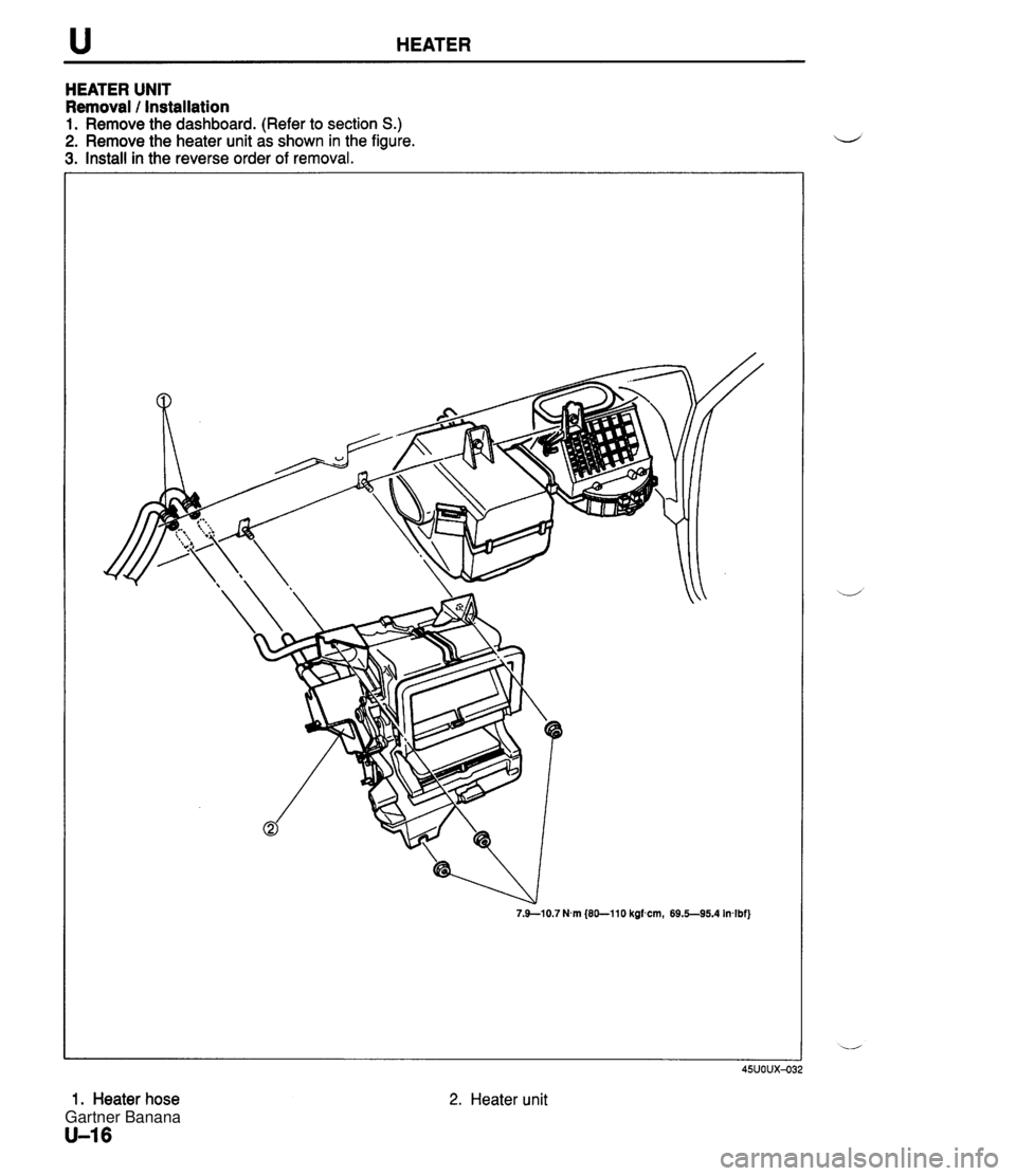
u HEATER HEATER UNIT Removal / Installation 1. Remove the dashboard. (Refer to section S.) 2. Remove the heater unit as shown in the figure. 3. Install in the reverse order of removal. 7.9-10.7 Nm (80-110 kgfcm, 69.5--95.4 In+bf] 1. Heater hose U-16 45UOUX4 2. Heater unit Gartner Banana
Page 1079 of 1708

HEATER u Disassembly / Assembly Disassemble and assemble as shown in the figure. 1. Heater core 2. Air mix door 3. Airflow mode door Inspection Heater core 1. Check the heater core fins for blockage. 2. If the fins are clogged, clean them. 3. Check the fittings for cracks or other damage. Replace the heater core if necessary. Gartner Banana
Page 1080 of 1708
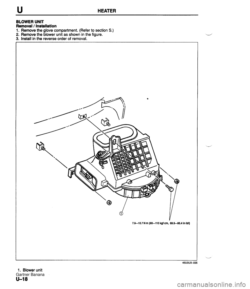
u HEATER BLOWER UNIT Removal / Installation 1. Remove the glove compartment. (Refer to section S.) 2. Remove the blower unit as shown in the figure. 3. Install in the reverse order of removal. 7.910.7 Nm (80-110 kof cm, 69.5-95.4 Inlbf) 1. Blower unit U-18 Gartner Banana
Page 1081 of 1708
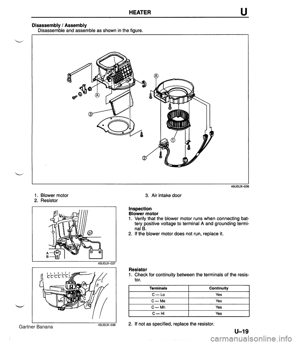
HEATER u Disassembly I Assembly is assemble and assemble as shown in the figure. 1. Blower motor 2. Resistor 3. Air intake door Inspection Blower motor 1. Verify that the blower motor runs when connecting bat- tery positive voltage to terminal A and grounding termi- nal B. 2. If the blower motor does not run, replace it. Resistor 1. Check for continuity between the terminals of the resis- tor. 1 Terminals Continuity I I C-LO I Yes I I C-Me I Yes I I C- Mh I Yes I I C-Hi I Yes I 2. If not as specified, replace the resistor. U-19 Gartner Banana
Page 1082 of 1708

u HEATER HEATER CONTROL UNIT Removal 1 Installation 1. Remove in the order shown in the figure. 2. Install in the reverse order of removal. 1. Center console 2. Vent outlet 3. Center panel assembly 4. Heater control unit Adjustment . . . . . . . . . . . . . . . . . . page U-22 Gartner Banana
Page 1083 of 1708
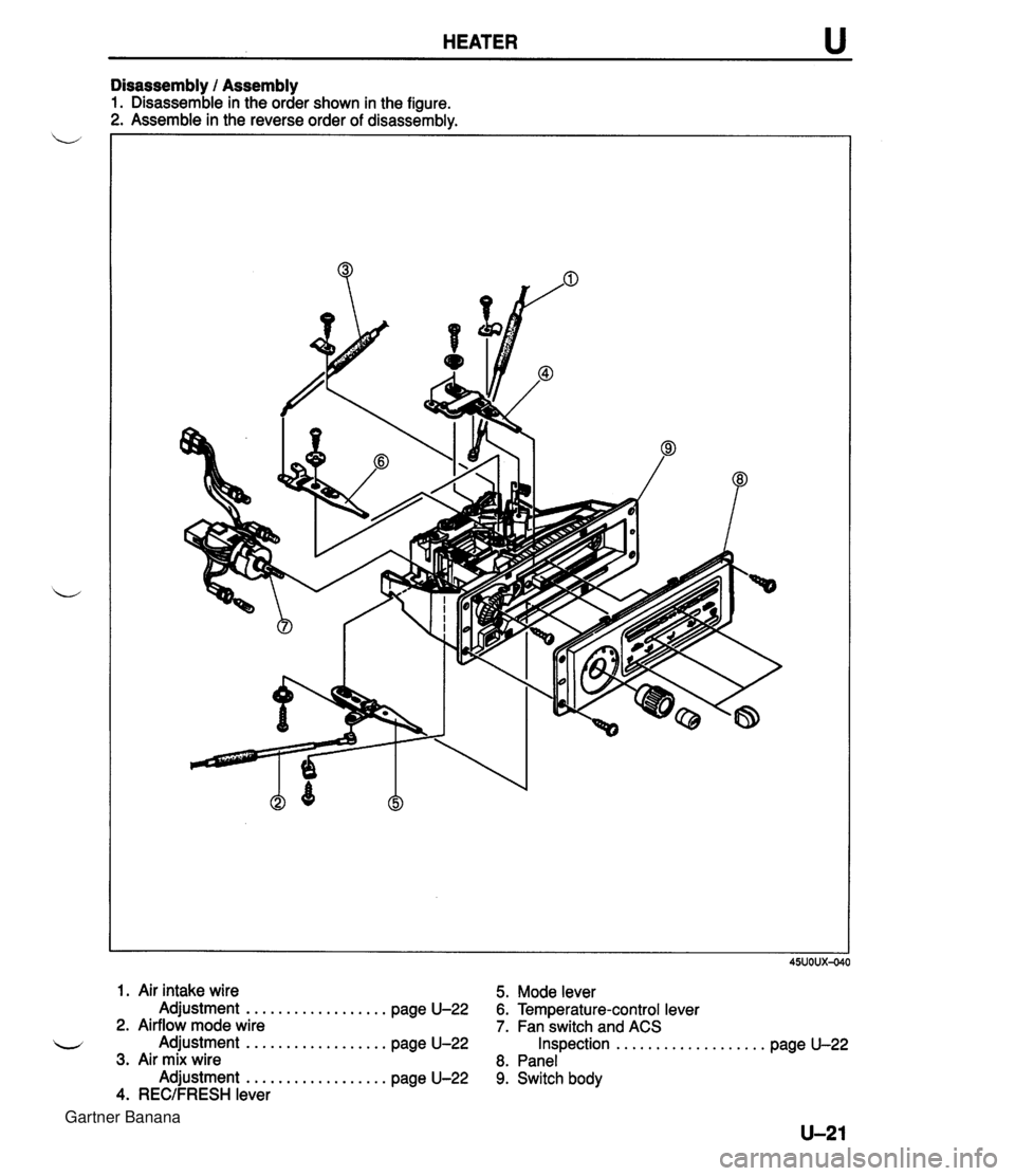
HEATER u Disassembly 1 Assembly 1. Disassemble in the order shown in the figure. 2. Assemble in the reverse order of disassembly. 1. Air intake wire 5. Mode lever Adjustment .................. page U-22 6. Temperature-control lever 2. Airflow mode wire 7. Fan switch and ACS u Adjustment .................. page U-22 Inspection ................... page U-22 3. Air mix wire 8. Panel Adjustment .................. page U-22 9. Switch body 4. RECIFRESH lever Gartner Banana
Page 1084 of 1708

u HEATER I_-K' AIR MIX WlRE -/ AIRFLOW MODE WlRE VENT bm -:JJ 45UOUX-04 AIR INTAKE WlRE / SHUTTER LEVER 45uoux-041 U-22 Inspection 1. Check for continuity between the terminals of the switch. Fan switch ACS Position I I I I I I I I OFF I I Terminal A~B~C~D~E~F~G~H I 1-1 I I I 1- 1- OFF First Second M: Continuity 0-0: Diode 2. If not as specified, replace the switch. Third 0 -0 0 Adjustment Air mix wire 1. Set the temperature-control lever to MAX HOT. 2. Connect and clamp the wire with the shutter lever on the heater unit all the way to the right. 3. Move the temperature-control lever to make sure the -, wire is securely attached and that it moves fully from HOT to COLD. Airflow mode wire 1. Set the mode lever to VENT. 2. Connect and clamp the wire with the shutter lever on the heater unit at its closest point. 3. Move the mode lever to make sure the wire is securely attached and that it moves fully from DEF to VENT. 0 RECIFRESH wire 1. Set the REC/FRESH lever to FRESH. 2. Connect and clamp the wire with the shutter lever on the blower unit at its closest point. 3. Move the RECJFRESH lever to make sure the wire is se- curely attached and that it moves fully from REC to FRESH. u 0 0-4 Gartner Banana
Page 1092 of 1708
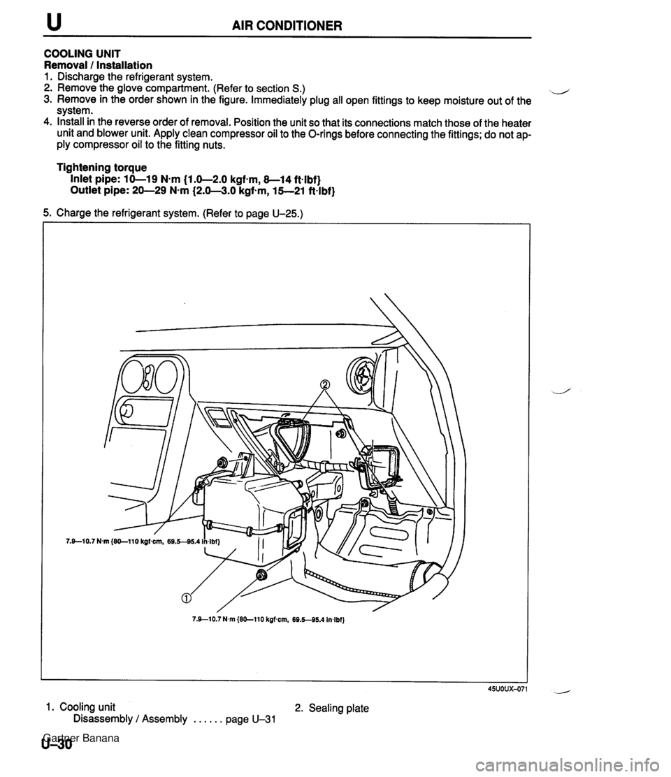
u AIR CONDITIONER COOLING UNIT Removal 1 Installation 1. Discharge the refrigerant system. 2. Remove the glove compartment. (Refer to section S.) il 3. Remove in the order shown in the figure. Immediately plug all open fittings to keep moisture out of the system. 4. Install in the reverse order of removal. Position the unit so that its connections match those of the heater unit and blower unit. Apply clean compressor oil to the O-rings before connecting the fittings; do not ap- ply compressor oil to the fitting nuts. Tightening torque Inlet pipe: 10-19 N-m (1.0-2.0 kgfsm, 8-14 ft-lbf} Outlet pipe: 20-29 N-m (2.0-3.0 kgf-m, 15--21 ft-lbf} 5. Charge the refrigerant system. (Refer to page U-25.) 7.910.7 N.m {EO-110 kgfmn, 69.5-95.4 In4bf} 45uoux-071 1. Cooling unit 2. Sealing plate Disassembly / Assembly . . . . . . page U-31 U-30 Gartner Banana
Page 1109 of 1708

TECHNICAL DATA MEASUREMENTS ......................... TD- 2 ................................... ENGINE TD- 2 .................... LUBRICATION SYSTEM TD- 5 ........................ COOLING SYSTEM TD- 5 FUEL AND EMISSION CONTROL SYSTEMS . TD- 6 ENGINE ELECTRICAL SYSTEM ............. TD- 7 .................................. CLUTCH TD- 7 .................. MANUAL TRANSMISSION TD- 8 AUTOMATIC TRANSMISSION ............... TD- 9 ....................... PROPELLER SHAFT TD-11 FRONT AND REAR AXLES ................. TD-12 STEERING SYSTEM ....................... TD-12 BRAKING SYSTEM ........................ TD-13 WHEELS AND TIRES ...................... TD-13 ............................. SUSPENSION TD-14 BODY ELECTRICAL SYSTEM ............... TD-15 HEATER AND AIR CONDITIONING SYSTEM . TD-15 STANDARD BOLT AND NUT TIGHTENING ................................. TORQUE TD-15 45UTDX-001 Gartner Banana
Page 1123 of 1708

TECHNICAL DATA 1 Charge I 1.4 Belt 1.4 r. BODY ELECTRICAL SYSTEM 1 Air bag I 2 1 Retractor 1.4 Item Wattage (Bulb trade number) Hold Anti lock Wamlng and indicator lights 1.4 1.4 Washer Rear window defroster Beam Turn (LH and RH) Illumination Malfanction indicator Brake 1.4 1.4 I Exterior lights 3.4 3.4 3.4 x 4 1.4 1.4 Headlights Front turn signawparking lights Front side marker lights License plate lights Rear turn signal lights Rear side marker lights Stop/taillights Back-UP linhts High-mount stoplight I 18.4 (921) ACS 1 1.4 Hazard switch 1.4 60140 2718 (1 157 NA) 3.8 (1 94) 7.5 27 (1 1 56) 3.8 (1 94) 2718 {I 157) 27 (1 1561 Interior llahts - I lllumination lights I Cruise control main switch I 1.4 I 5 Ash tray U. HEATER AND AIR CONDITIONING SYSTEM I Item I Specit lcations I 3.4 Heater control switch ane el I 1.4 STANDARD BOLT AND NUT TIGHTENING TORQUE Refrigerant amount S (04 Compressor oil amount rnl {cc, fl oz) Refrigerant normal pressure MPa (kgflcm2, psi) 600 {2 1.21 130-1 70 {I 30-1 70,3.9-5.1) Low pressure: 0.154.25 (1 .5-2.5,21-361 Hiah Pressure: 1 37-1.57 (1 4--16, 199--228) Gartner Banana