relay MAZDA MX-5 1994 Owner's Manual
[x] Cancel search | Manufacturer: MAZDA, Model Year: 1994, Model line: MX-5, Model: MAZDA MX-5 1994Pages: 1708, PDF Size: 82.34 MB
Page 240 of 1708
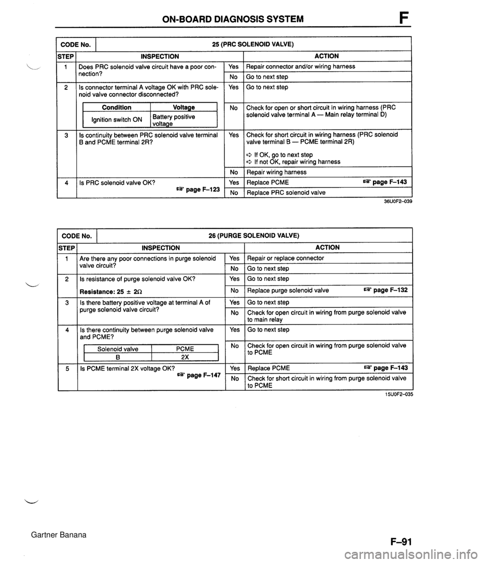
ON-BOARD DIAGNOSIS SYSTEM CODE No. 25 (PRC SOLENOID VALVE) I Condition Ignition switch ON ACTION Repair connector and/or wiring harness Go to next step Go to next step STEP 1 2 Check for open or short circuit in wiring harness (PRC Battery positive solenoid valve terminal A - Main relay terminal D) voltaae 3 CODE No. 26 (PURGE SOLENOID VALVE) iTEP I INSPECTION I ACTION 4 ' I Are there any poor connections in purge solenoid valve circuit? INSPECTION I . - I Is continuity between PRC solenoid valve terminal B and PCME terminal 2R? I 2 Is resistance of purge solenoid valve OK? Does PRC solenoid valve circuit have a poor con- nection? Is connector terminal A voltage OK with PRC sole- noid valve connector disconnected? 36UOF2-039 Is PRC solenoid valve OK? as page F-123 Is there battery positive voltage at terminal A of purge solenoid valve circuit? Yes No Yes Yes Solenoid valve Check for short circuit in wiring harness (PRC solenoid valve terminal B - PCME terminal 2R) No Yes ' No 5 Is PCME terminal 2X voltage OK? page F-147 Q If OK, go to next step e If not OK, repair wiring harness Repair wiring harness Replace PCME page F-143 Replace PRC solenoid valve Yes Repair or replace connector No Go to next step Yes Go to next step No Replace purge solenoid valve page F-132 Yes Go to next step No Check for open circuit in wiring from purge solenoid valve I to main relay I No Check for open circuit in wiring from purge solenoid valve I to PcME I Yes I Replace PCME page F-143 No Check for short circuit in wiring from purge solenoid valve to PCME 15UOF2-035 Gartner Banana
Page 241 of 1708

F ON-BOARD DIAGNOSIS SYSTEM CODE NO. I 28 (EGR SOLENOID VALVE(VACUUM)) I I iTEP I INSPECTION ACTION (vacuum) circuit? valve (vacuum) connector disconnected OK? - Yes Repair or replace connector I Go to next step Yes Go to next step No - Yes - No 3 Check for open or short circuit in wiring from EGR solenoid valve (vacuum) terminal A to main relay terminal I Condition 1 Voltage IG switch ON I Battery positive voltage Is continuity between EGR solenoid valve (vacu- um) terminal B and PCME terminal IT OK? Check for short circuit in wiring from EGR solenoid valve (vacuum) terminal B to PCME terminal IT 0 If OK, go to next step 0 If not OK, repair or replace wiring harness Repair or replace wire harness Yes - No 4 Replace PCME Replace EGR solenoid valve (vacuum) Is EGR solenoid valve (vacuum) OK? CODE No. I - 29 (EGR SOLENOID VALVE(VENT)) I iTEP I INSPECTION ACTION I I If there a poor connection in EGR solenoid valve (vent) circuit? Repair or replace connector Go to next step Go to next step 1 Is connector terminal A voltages with EGR solenoid valve (vent) connector disconnected OK? Check for open or short circuit in wiring from EGR solenoid valve (vent) terminal A to main relay terminal I Condition I Voltage G switch ON I Battery positive voltage 1 Yes 3 Check for short circuit in wiring from EGR solenoid valve (vent) terminal B to PCME terminal 1 R Is continuity between EGR solenoid valve (vent) terminal B and PCME terminal 1 R OK? 0 If OK, go to next step s If not OK, repair or replace wiring harness Re~air or reolace wire harness I 4 Replace PCME I Replace EGR solenoid valve (vent) 39UOFX-110 Is EGR solenoid valve (vent) OK? No Yes No Gartner Banana
Page 242 of 1708
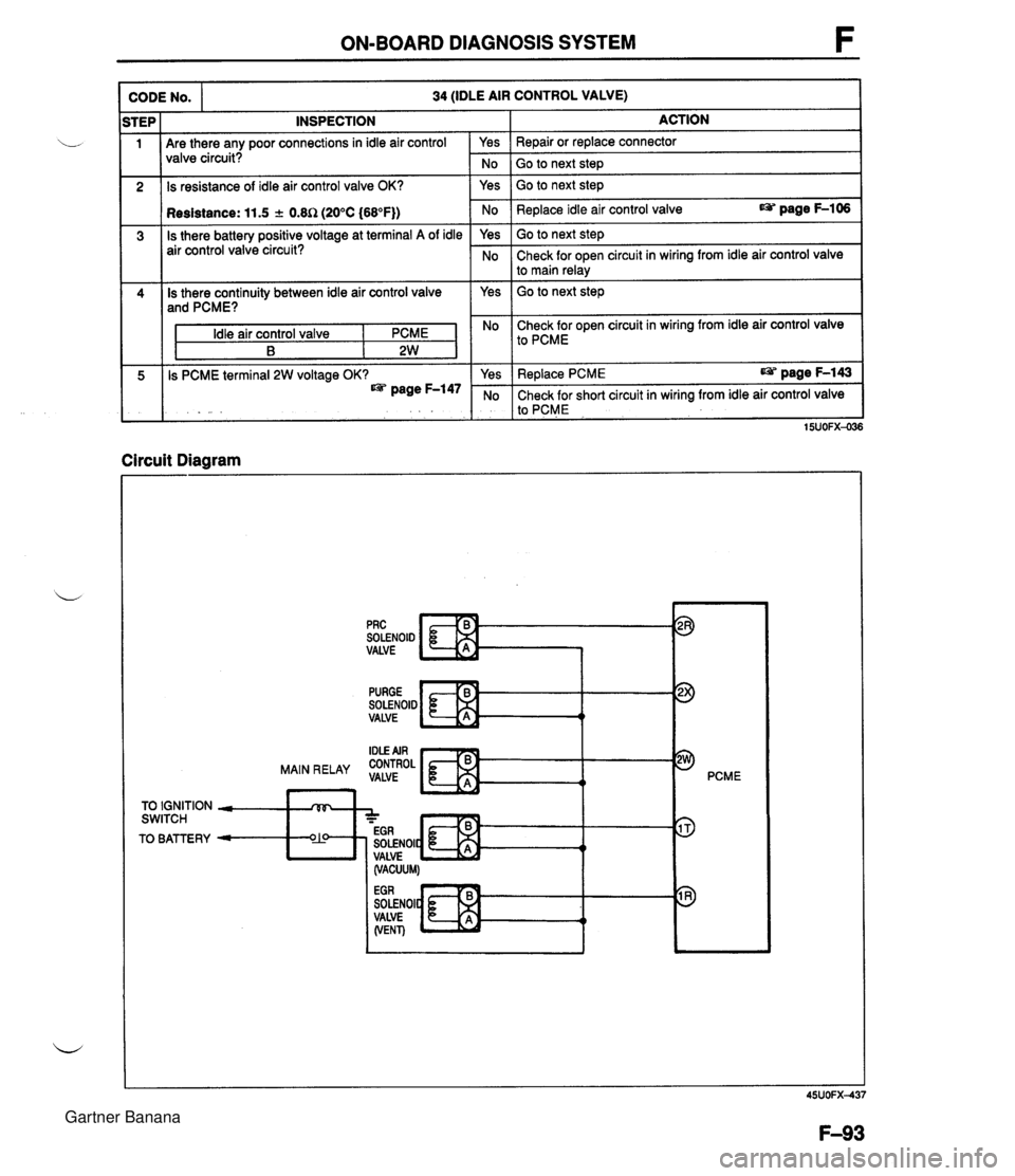
ON-BOARD DIAGNOSIS SYSTEM INSPECTION Are there any poor connections in idle air control valve circuit? CODE NO. Is resistance of idle air control valve OK? 34 (IDLE AIR CONTROL VALVE) 1 Resistance: 11.5 + 0.8R (20°C (68°F)) Is there battery positive voltage at terminal A of idle air control valve circuit? Is there continuity between idle air control valve and PCME? Idle air control valve I PCME B 2W Is PCME terminal 2W voltage OK? page F-147 Circuit Diagram No 1 Go to next ste~ I Yes ACTION Repair or replace connector Yes No Yes Go to next step I I Go to next step Replace idle air control valve page F-106 Yes No No Check for open circuit in wiring from idle air control valve I to PCME Go to next step Check for open circuit in wiring from idle air control valve to main relay SOLENOID VALVE pRc c Yes No PURGE SOLENOID VALVE Replace PCME page F-143 Check for short circuit in wiring from idle air control valve to PCME t PCME 15UOFX-036 TO IGNITION - rVF, SWITCH A - - EGR TO BATTERY - O?! SOLENOIC t 4 I, VALVE (VACUUM) SOLENOI VALVE (VENT) Gartner Banana
Page 247 of 1708
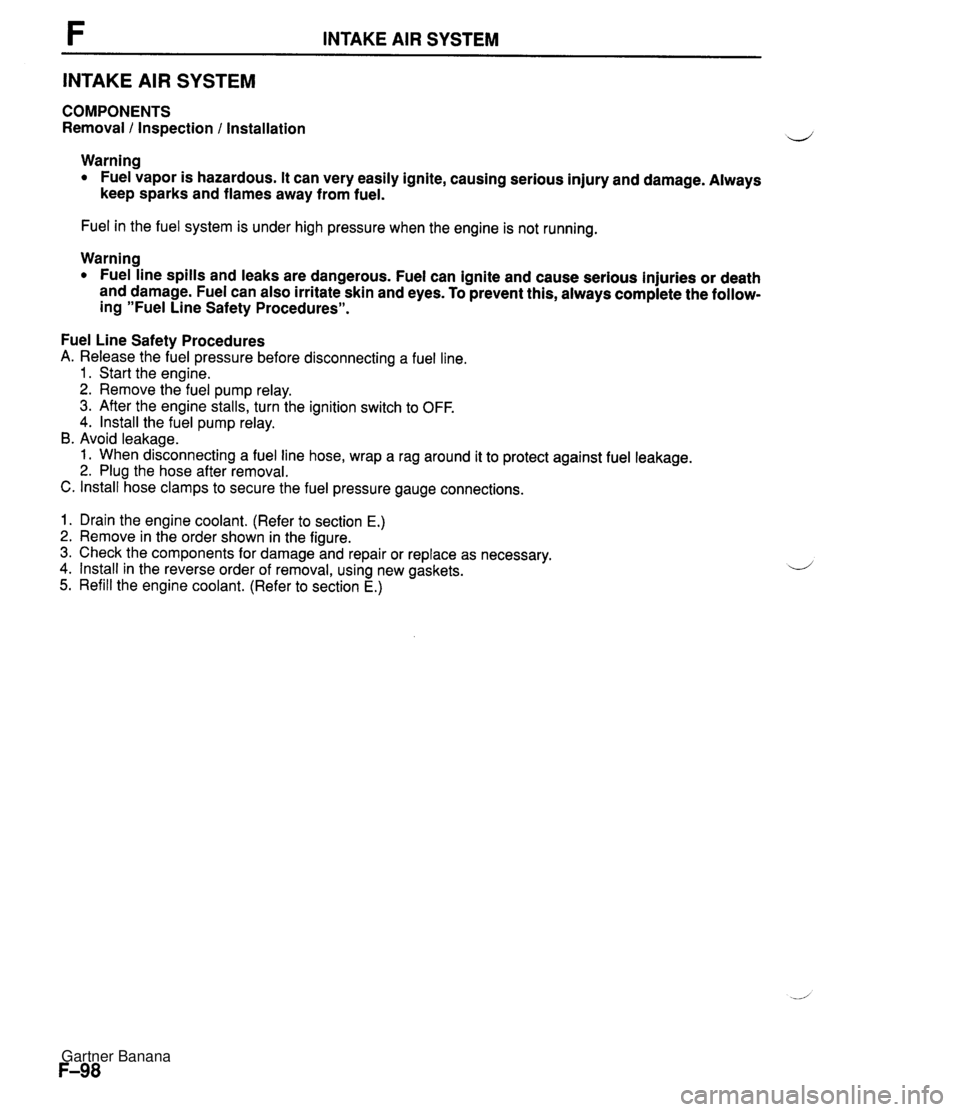
INTAKE AIR SYSTEM INTAKE AIR SYSTEM COMPONENTS Removal 1 Inspection l Installation Warning Fuel vapor is hazardous. It can very easily ignite, causing serious injury and damage. Always keep sparks and flames away from fuel. Fuel in the fuel system is under high pressure when the engine is not running. Warning Fuel line spills and leaks are dangerous. Fuel can ignite and cause serious injuries or death and damage. Fuel can also irritate skin and eyes. To prevent this, always complete the follow- ing "Fuel Line Safety Procedures". Fuel Line Safety Procedures A. Release the fuel pressure before disconnecting a fuel line. 1. Start the engine. 2. Remove the fuel pump relay. 3. After the engine stalls, turn the ignition switch to OFF. 4. lnstall the fuel pump relay. B. Avoid leakage. 1. When disconnecting a fuel line hose, wrap a rag around it to protect against fuel leakage. 2. Plug the hose after removal. C. lnstall hose clamps to secure the fuel pressure gauge connections. 1. Drain the engine coolant. (Refer to section E.) 2. Remove in the order shown in the figure. 3. Check the components for damage and repair or replace as necessary. 4. lnstall in the reverse order of removal, using new gaskets. 5. Refill the engine coolant. (Refer to section E.) Gartner Banana
Page 256 of 1708

FUEL SYSTEM F FUEL SYSTEM DESCRIPTION . This system supplies the necessary fuel for combustion at a constant pressure to the fuel injectors. Fuel is metered and injected into the intake manifold according to the injection control signals from the power- train control module (engine). The system consists of the fuel tank, the fuel pump, the fuel filters, the fuel distributor, the pressure regulator, the fuel injectors, and the fuel pump relay. I I 1. Fuel tank 5. Fuel pump relay Removal / Inspection / Inspection .................. page F-117 Installation ................ page F-111 Replacement ............... page F-117 2. Fuel filter 6. Pressure regulator Replacement ............... page F-113 Inspection .................. page F-118 3. Fuel pump Replacement ............... page F-119 .................. w Inspection page F-114 7. Fuel injector Replacement ............... page F-115 Inspection .................. page F-119 4. Fuel distributor Removal ................... page F-119 Installation ................. page F-121 Gartner Banana
Page 257 of 1708
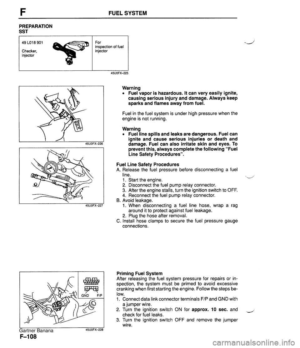
FUEL SYSTEM PREPARATION SST 49 LO1 8 901 For inspection of fuel Checker, injector injector Warning Fuel vapor is hazardous. It can very easily ignite, causing serious injury and damage. Always keep sparks and flames away from fuel. Fuel in the fuel system is under high pressure when the engine is not running. Warning Fuel line spills and leaks are dangerous. Fuel can ignite and cause serious injuries or death and damage. Fuel can also irritate skin and eyes. To prevent this, always complete the following "Fuel Line Safety Procedures". Fuel Line Safety Procedures A. Release the fuel pressure before disconnecting a fuel line. xd 1 . Start the engine. 2. Disconnect the fuel pump relay connector. 3. After the engine stalls, turn the ignition switch to OFF. 4. Reconnect the fuel pump relay connector. B. Avoid leakage. 1. When disconnecting a fuel line hose, wrap a rag around it to protect against fuel leakage. 2. Plug the hose after removal. C. Install hose clamps to secure the fuel pressure gauge connections. Priming Fuel System After releasing the fuel system pressure for repairs or in- spection, the system must be primed to avoid excessive cranking when first starting the engine. Follow the steps be- low. 1. Connect data link connector terminals F/P and GND with a jumper wire. 2. Turn the ignition switch ON for approx. 10 sec. and - check for fuel leaks. 3. Turn the ignition switch OFF and remove the jumper wire. Gartner Banana
Page 263 of 1708

F FUEL SYSTEM FUEL PUMP Inspection Fuel pump operation 1. Connect the data link connector terminals F/P and GND , with a jumper wire. 2. Remove the fuel filler cap. 3. Turn the ignition switch ON. 4. Listen for operational sound of the fuel pump at the filler inlet. 5. Install the fuel filler cap. 6. If no sound was heard, measure the voltage between the fuel pump connector wire to ground. Voltage: Battery positive voltage 7. If not correct, check the fuel pump relay and its circuits. (Refer to page F-116.) 8. If the voltage is normal, check for continuity between fuel pump connector (6) and a ground. 9. If there is continuity, replace the fuel pump. 10. If no continuity, repair the ground circuit. Hold pressure Perform this inspection if the fuel pressure hold inspec- tion is not as specified. (Refer to page F-109.) Warning Fuel line spills and leaks can be dangerous. Fuel can ignite and cause serious injuries or death and can damage the vehicle. Fuel can also irritate skin and eyes. To prevent this from happening, release the fuel pressure according to "Fuel Line Safety Procedures" on page F-108. 1. Disconnect the negative battery terminal. 2. Connect a fuel pressure gauge to the fuel main pipe and plug the outlet of the fuel pressure gauge as shown. (Install clamps as shown.) 3. Connect the negative battery terminal. Gartner Banana
Page 266 of 1708

FUEL SYSTEM F FUEL PUMP RELAY Inspection Apply battery positive voltage and a ground to the termi- nals below and check the fuel pump relay operation as described. If not as specified, replace the fuel pump relay. B+: Battery positive voltage Replacement 1. Remove the undercover. B+ A 2. Remove the fuel pump relay. 3. Install in the reverse order of removal. Grounded B Correct result C - E: Continuity Gartner Banana
Page 284 of 1708

AIC CUT-OFF CONTROL SYSTEM AIC CUT-OFF CONTROL SYSTEM DESCRIPTION An NC cut-off system is used to improve idle smoothness after just starting the engine and to improve - acceleration performance. IGNITION SWITCH POWERTRAIN CONTROL MODULE (ENGINE) CRANKSHAFT POSITION - I DETERMINA- TION OF NC CUT-OFF & $1 . 1 THROTTLE I POSITION SENSOR AIC RELAY IGNITION SWITCH SENSOR 7 After engine has been started - The AJC is cut-off for 2 sec. just after the engine is started. Acceleration The AIC is cut-off upon wide-open-throttle acceleration for approx. 5 sec. Gartner Banana
Page 285 of 1708
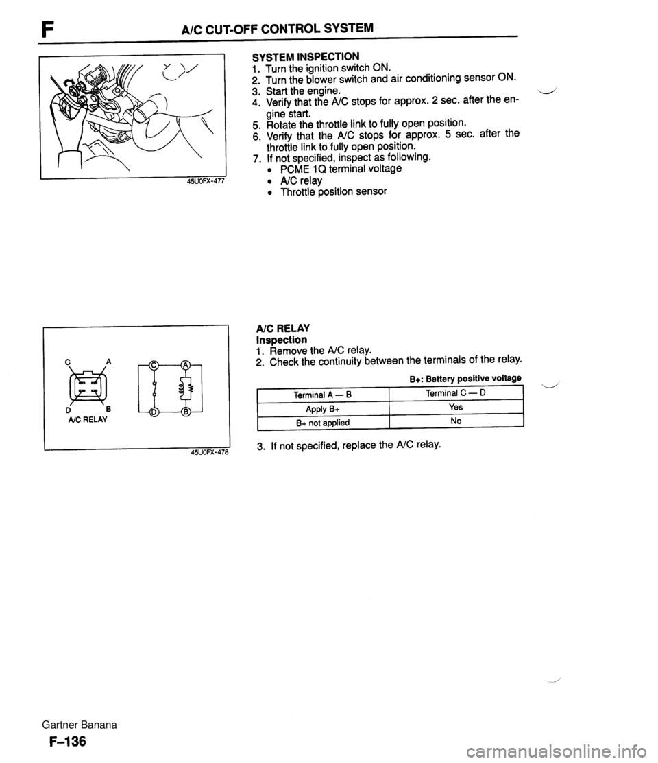
F A/C CUT-OFF CONTROL SYSTEM D B AIC RE LAY SYSTEM INSPECTION 1. Turn the ignition switch ON. 2. Turn the blower switch and air conditioning sensor ON. 3. Start the engine. d 4. Verify that the A/C stops for approx. 2 sec. after the en- gine start. 5. Rotate the throttle link to fully open position. 6. Verify that the A/C stops for approx. 5 sec. after the throttle link to fully open position. 7. If not specified, inspect as following. PCME 1Q terminal voltage A/C relay Throttle position sensor AIC RELAY Inspection 1. Remove the A/C relay. 2. Check the continuity between the terminals of the relay. 3. If not specified, replace the A/C relay. B+: Battery positive voltage Terminal A - B Apply B+ B+ not applied Terminal C - D Yes No Gartner Banana