fuel filter MAZDA MX-5 1994 Workshop Manual
[x] Cancel search | Manufacturer: MAZDA, Model Year: 1994, Model line: MX-5, Model: MAZDA MX-5 1994Pages: 1708, PDF Size: 82.34 MB
Page 32 of 1708
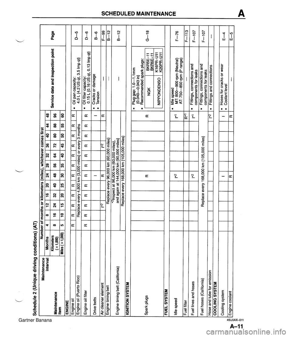
Schedule 2 (Unique driving conditions) (AT) Maintenance interval Maintenance item ENGINE Engine oil I R I R I R I R I R I R I R I R I R I R I R I R Engine oil filter Drive belts Number of months or kilometers {miles}, whichever comes first eoilpancapacity: 4.0 L {4.2 US qt, 3.5 Imp qt} Engine oil (Puerto Rico) I I IGNITION SYSTEM Service data and inspection point Months Kilometers (x 1,m) Miles (x 1,000) D-5 Replace every 4,800 km (3,000 miles) or every 3 months I I I I I I I I - - Engine timing belt (California) Spark plugs Page - - Air cleaner element I I FUEL SYSTEM 4 8 5 I F-99 8-1 2 -. . . '21nspect at 96,000 km {60,000 miles}, and again at 144,000 km {90,000 miles) Replace every 168,000 km (1 05,000 miles) - - R*' - 1'1 l Oilfiltercapacity: 0.15 L (0.16 US qt, 0.13 Imp qt} l Cracks or damage l Tension I R 1 Ie2 1 Engine timing belt ~ --- - - l Plug gap: 1 .&I -1 mm (0.040-4.043 in) l Recommended dark ~luas: 8 16 10 D-6 B-6 Replace every 96,000 km (60,000 miles) Idle speed Fuel filter Fuel lines and hoses NGK , BKRGE-11 BKR5E-I 1 12 24 15 IRI I*2 lt2 l Idle speed MT: 800-900 rpm (Neutral) 1 F-76 AT: 75M0 rpm (P range) 16 32 20 I!*'2 1 20 40 25 24 48 30 - Fittings, connections and com~onents for leaks 36 72 45 F-113 F-1 07 Fuel hoses (California) Hose and tube for emission 28 56 35 Cooling system Engine coolant 32 64 40 COOLING SYSTEM Replace every 168,000 km {I 05,000 miles} 1 1*2 48 96 60 40 80 50 I R 44 88 55 l Fittings, connections and components for leaks Fittings and connections F-1 07 - I R l Hoses for cracks or wear l Coolant level - E4 E-5 Gartner Banana
Page 35 of 1708
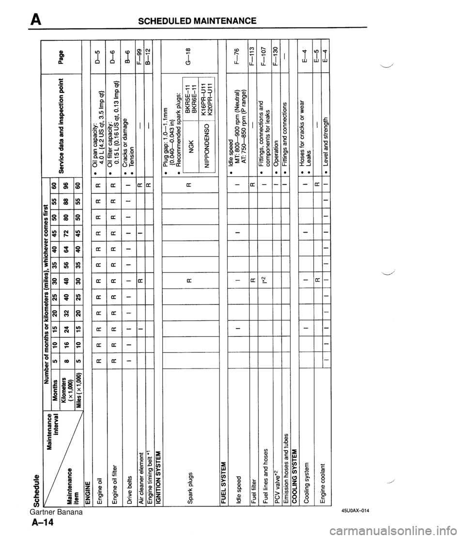
Schedule interval Maintenance ENGINE Number of months or kilometers {miles), whichever comes first I -. Months 5 10 15 20 25 30 35 40 45 50 55 60 Kilometers 8 16 24 32 40 48 56 64 72 80 88 96 - Service data and inspection point 1~1.000~ Page Spark plugs FUEL SYSTEM -- Plug gap: 1 .GI .l mm {0.04M.043 in) l Recommended spark plugs: D-5 D-6 B-6 F-99 8-1 2 IGNITION SYSTEM R I I Engine oil Engine oil filter Drive belts Air cleaner element Engine timing belt 'l R I R I F-76 F-1 1 3 F-107 F-I30 - Idle speed Fuel filter Fuel lines and hoses PCV valve'2 Emission hoses and tubes R I COOLING SYSTEM I Cooling system Engine coolant R I R I I E4 E-5 E4 I R I R I R I R I*z I l Hoses for cracks or wear l Leaks - Level and strength I R RR I R R R I I R I OilPancapacity: 4.0 L (4.2 US qt, 3.5 Imp qt) 0 Oil filter capacity: 0.15L(0.16USqt,0.13Impqt) 'Cracksordamage 0 Tension - - R I I I I I R I l ldle speed MT: 800-900 rpm (Neutral) AT 750-850 rpm (P range) - l Fittings, connections and components for leaks Operation Fittings and connections I I R I I I I I I I I I R I Gartner Banana
Page 150 of 1708
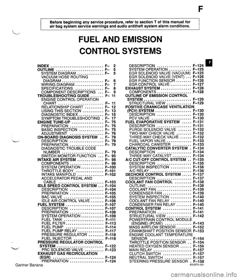
Before beginning any service procedure. refer to section T of this manual for air bag system service warnings and audio antitheft system alarm conditions . FUEL AND EMISSION CONTROL SYSTEMS INDEX ............................ F- 2 ......................... OUTLINE F- 5 .............. SYSTEM DIAGRAM F- 5 VACUUM HOSE ROUTING DIAGRAM ...................... F- 6 WIRING DIAGRAM ............... F- 7 SPECIFICATIONS ............... F- 8 COMPONENT DESCRIPTIONS ... F- 9 ....... TROUBLESHOOTING GUIDE F- 11 ENGINE CONTROL OPERATION CHART ........................ F- 11 RELATIONSHIP CHART .......... F- 12 USING THIS SECTION ........... F- 13 DIAGNOSTIC INDEX ............. F- 15 SYMPTOM TROUBLESHOOTING . F- 17 PREPARATION ................... F- 75 ............. BASIC INSPECTION F- 75 .................. ADJUSTMENT F- 76 ON-BOARD DIAGNOSIS SYSTEM . . F- 78 DESCRIPTION .................. F- 78 PREPARATION .................. F- 79 DIAGNOSTIC TROUBLE CODE NUMBER ...................... F- 79 ... SWITCH MONITOR FUNCTION F- 95 INTAKE AIR SYSTEM .............. F- 98 COMPONENTS .................. F- 98 SYSTEM OPERATION ............ F-100 THROTTLE BODY ............... F-101 INTAKE MANIFOLD .............. F-102 ACCELERATOR PEDAL AND CABLE ........................ F-103 IDLE SPEED CONTROL SYSTEM ... F-104 DESCRI PTlON .................. F-104 PREPARATION .................. F-105 BAC VALVE ..................... F-105 IDLE AIR CONTROL VALVE ....... F-106 FUEL SYSTEM .................... F-107 DESCRIPTION .................. F-107 PREPARATION .................. F-108 SYSTEM OPERATION ............ F-109 FUEL TANK ..................... F-111 FUEL FILTER .................... F-113 FUEL PUMP .................... F-114 FUEL PUMP RELAY .............. F-117 PRESSURE REGULATOR ........ F-118 FUEL INJECTOR ................ F-119 PRESSURE REGULATOR CONTROL SYSTEM ......................... F-122 PRC SOLENOID VALVE .......... F-123 EXHAUST GAS RECIRCULATION (EGR) ........................... F-124 PREPARATION .................. F-124 .................. DESCRIPTION F-124 SYSTEM OPERATION F-125 ............ EGR SOLENOID VALVE (VACUUM) F-125 EGR SOLENOID VALVE (VENT) ... F-126 ......... EGR FUNCTION SENSOR F-126 ........... EGR CONTROL VALVE F-127 ................ EXHAUST SYSTEM F-128 .................. COMPONENTS F-128 OUTLINE OF EMISSION CONTROL ......................... SYSTEM F-129 ............. STRUCTURAL VIEW F-129 POSITIVE CRANKCASE VENTILATION ................... (PCV) SYSTEM F-130 ' DESCRIPTION .................. F-I ..................... PCV VALVE F-1 ..... FUEL EVAPORATIVE SYSTEM F- .................. DESCRIPTION F- ....... PURGE SOLENOID VALVE F- ........ TWO-WAY CHECK VALVE F- ...... THREE-WAY CHECK VALVE F- ............. FUEL VAPOR VALVE F- .......... CHARCOAL CANISTER F- CATALYTIC CONVERTER SYSTEM . F- .................. DESCRIPTION F- .......... THREE-WAY CATALYST F- AIC CUT-OFF CONTROL SYSTEM . . F- .................. DESCRIPTION F- ........... SYSTEM INSPECTION F- ...................... A/c RELAY F-1 36 ..... DECHOKE CONTROL SYSTEM F-137 .................. DESCRIPTION F-137 ......... COOLANT FAN CONTROL F-138 ....................... OUTLINE F-138 .................. COOLANT FAN F-139 ............... CONDENSER FAN F-139 ........... SYSTEM INSPECTION F-140 ........... COOLANT FAN RELAY F-140 ........ CONDENSER FAN RELAY F-140 ............... CONTROL SYSTEM F-141 .................. PREPARATION F-141 ............. STRUCTURAL VIEW F-142 POWERTRAIN CONTROL MODULE .............. (ENGINE) (PCME) F-143 ........ MASS AIRFLOW SENSOR F-152 CRANKSHAFT POSITION SENSOR F-153 ENGINE COOLANT TEMPERATURE ...................... SENSOR F-154 THROTTLE POSITION SENSOR . . F-154 HEATED OXYGEN SENSOR ...... F-156 MAIN RELAY .................... F-157 ............... CLUTCH SWITCH F-157 NEUTRAL SWITCH .............. F-157 STEERING PRESSURE SENSOR . F-158 45UOFX-001 Gartner Banana
Page 153 of 1708

INDEX 1. Fuel tank 4. Two-way check valve .................. Removal / Inspection / Inspection page F-132 Installation ................ page F-111 5. Three-way check valve .................. 2. Fuel filter Inspection page F-132 Replacement ............... page F-113 6. Fuel vapor valve .................. 3. Fuel pump Inspection page F-133 .................. Inspection page F-114 ............... Replacement page F-115 1. Three-way catalyst 2. Exhaust components d Inspection / Replacement .... page F-134 Removal / Inspection / Installation ............... page F-128 Gartner Banana
Page 154 of 1708
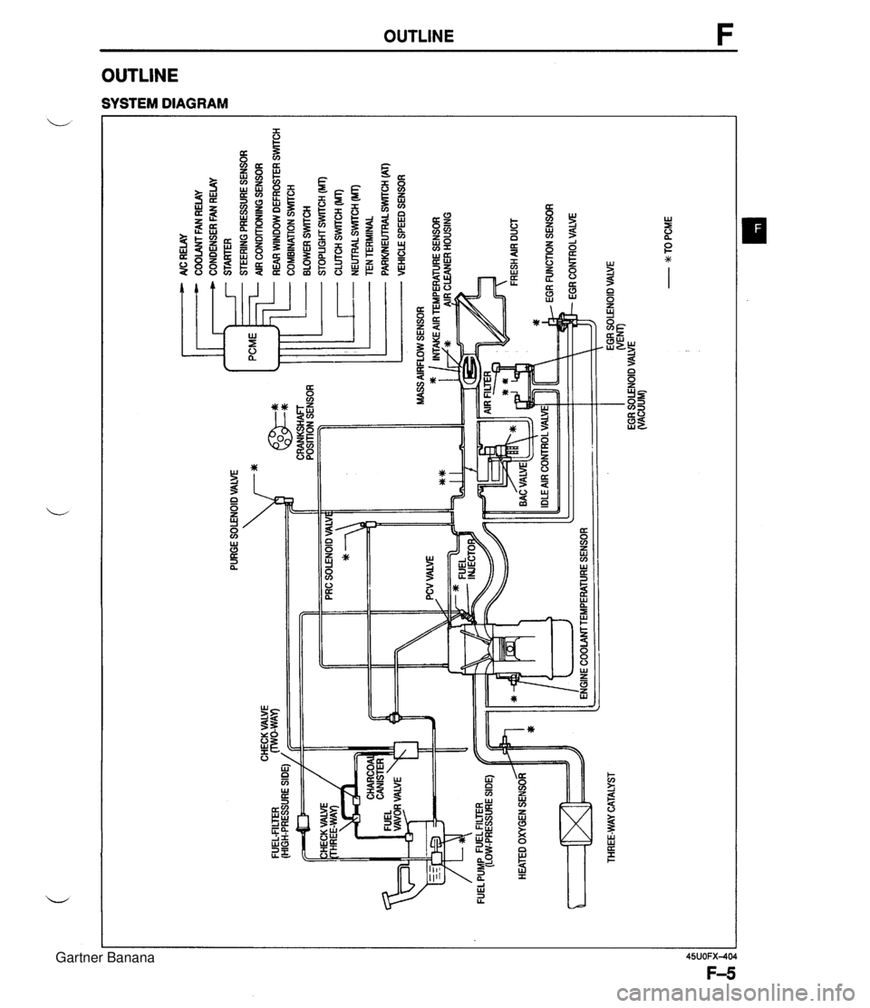
PURGE SOLENOID VALVE 7* AlC RELAY COOLANT FAN RELAY CONDENSER FAN RELAY STARTER STEERING PRESSURE SENSOR AIR CONDITIONING SENSOR ... CHECK VALVE FUEL-FILTER (HIGH-PRESSURE SIDE) / CRANKSHAFT POSITION SENSOR HEATED OXYGEN SENSOR ltT=I THREE-WAY CATALYST - REAR WINDOW DEFROSTER SWITCH COMBINATION SrmCH BLOWER SWlTCH STOPLIGHT SWITCH (MT) CLUTCH SWITCH (MT) - NEUTRALSWrrCH (MT) TEN TERMINAL PARWEUTRAL SWITCH (AT) VEHICLE SPEED SENSOR ENGINE COOLAMTEMPERATURE SENSOR EGR SOLENOID VALVE WEM) EGR SOLENOID VALVE (VACUUM) - w TO PCME Gartner Banana
Page 157 of 1708
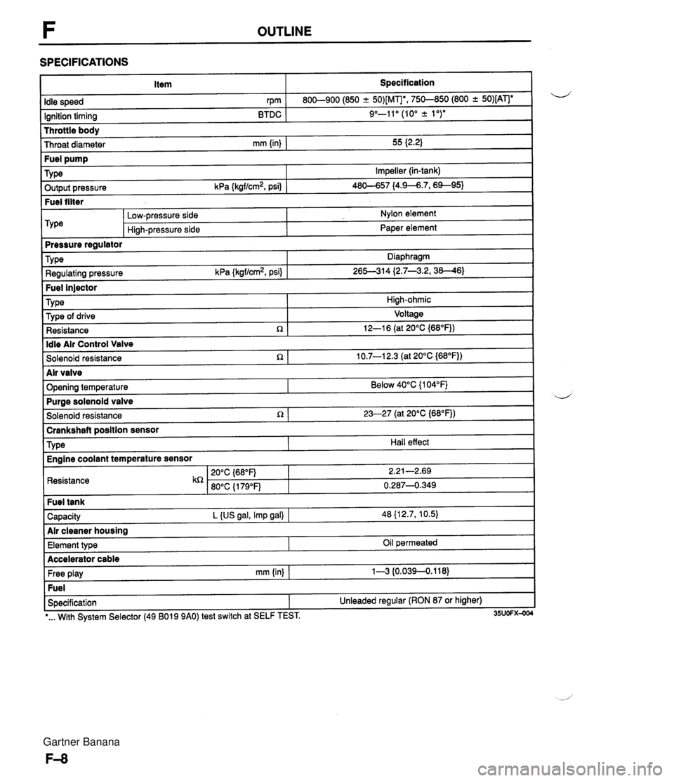
F OUTLINE SPECIFICATIONS Item Specification I Throttle body Throat diameter mm {in) I 55 I2.2) Idle speed rpm Ignition timing BTDC 800-900 (850 -+ 50)[MIb, 750-850 (800 + 50)[ATJe 9"-11" (10" k 1 ")* ~ut~~~ressure kPa {kgf/cm2, psi) 1 46-57 14.9--6.7,6%95) Fuel filter Fuel pump TY pe -- m&e regulator Impeller (in-tank) Low-pressure side Hi~h-pressure side Nylon element Paper element Fuel injector TY pe I High-ohmic Type Regulating pressure kPa {kgf/cm2, psi) Diaphragm 26S314 (2.7--3.2,38--46) ldle Air Control Valve Solenoid resistance n 1 10.7-1 2.3 (at 20°C {M°F)) Type of drive Resistance R Voltage 12-1 6 (at 20°C {68"F)) I Solenoid resistance 1 23-27 (at 20°C (68"FJ) I -- brankshaft position sensor d Air valve Opening temperature I Resistance Below 40°C {I 04°F) TY pe Capacity L {US gal, Imp gal) I 48 {12.7, 10.5) Air cleaner housing Purae solenoid valve Hall effect Engine coolant temperature sensor Free play mm (in) I 1-3 {0.0394.118) Fuel Specification 1 Unleaded regular (RON 87 or higher) Element type I I -. I *... With System Selector (49 B019 9AO) test switch at SELF TEST. 35UOFX-004 Oil permeated Accelerator cable Gartner Banana
Page 158 of 1708
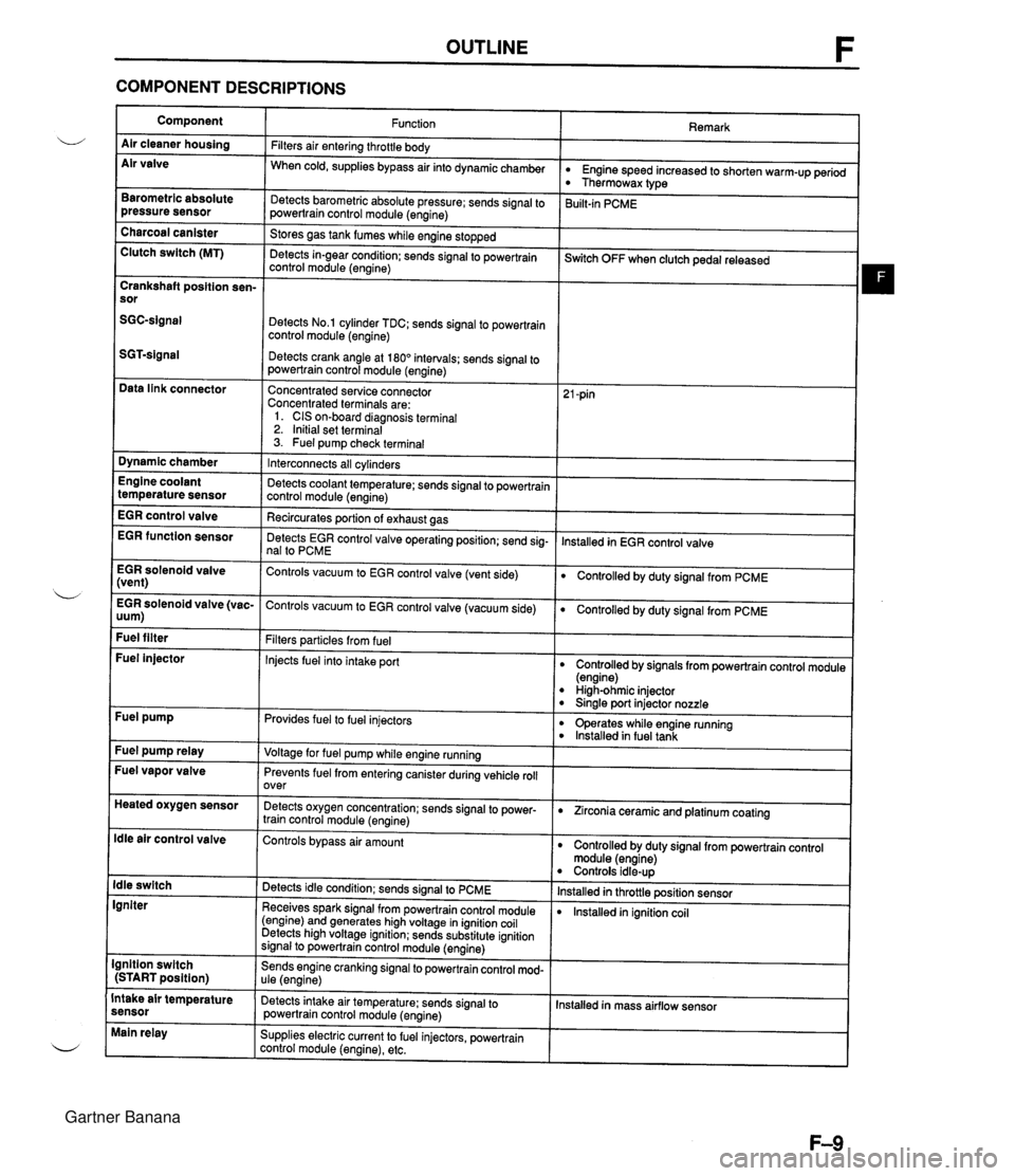
OUTLINE F COMPONENT DESCRIPTIONS Component Air cleaner housing Air valve Remark Function Filters air entering throttle body When cold, supplies bypass air into dynamicchamber w Engine speed increased to shorten warm-up period Thermowax type Barometric absolute pressure sensor Detects barometric absolute pressure; sends signal to powertrain control module (engine) 3uilt-in PCME Charcoal canister Clutch switch (MT) Stores gas tank fumes while engine stopped Detects in-gear condition: sends signal to powertrain control module (engine) --- ~witch OFF when clutch pedal released Crankshaft position sen- sor Detects No.1 cylinder TDC; sends signal to powertrain control module (engine) Detects crank angle at 180" intervals; sends signal to powertrain control module (engine) Data link connector Concentrated service connector Concentrated terminals are: 1. CIS on-board diagnosis terminal 2. Initial set terminal 3. Fuel pump check terminal Dynamic chamber Interconnects all cylinders Detects coolant temperature; sends signal to powertrain control module (engine) Recircurates oortion of exhaust aas Engine coolant temperature sensor EGR control valve lnstalled in EGR control valve EGR function sensor Detects EGR control valve operating position; send sig- nal to PCME EGR solenoid valve (vent) Controls vacuum to EGR control valve (vent side) Controlled by duty signal from PCME . - EGR solenoid valve (vac- Controls vacuum to EGR control valve (vacuum side) 0 Controlled by duty signal from PCME uum) Fuel filter Filters particles from fuel Injects fuel into intake port Fuel injector Controlled by signals from powertrain control module (engine) High-ohmic injector 0 Sinale port injector nozzle Fuel pump Provides fuel to fuel injectors 0 operates while engine running lnstalled in fuel tank Fuel pump relay Voltage for fuel pump while engine running Fuel vapor valve Prevents fuel from entering canister during vehicle roll over Heated oxygen sensor Detects oxygen concentration; sends signal to power- train control module (engine) 0 Zirconia ceramic and platinum coating ldle air control valve Controls bypass air amount Controlled by duty signal from powertrain control module (engine) Controls idle-up lnstalled in throttle position sensor lnstalled in ignition coil ldle switch Igniter Detects idle condition; sends signal to PCME Receives spark signal from powertrain control module (engine) and generates high voltage in ignition coil Detects high voltage ignition; sends substitute ignition signal to powertrain control module (engine) Ignition switch (START position) Sends engine cranking signal to powertrain control mod- ule (engine) Intake air temperature sensor Detects intake air temperature: sends signal to powertrain control module (engine) Installed in mass airflow sensor Main relay Supplies electric current to fuel injectors, powertrain control module (engine), etc. Gartner Banana
Page 170 of 1708
![MAZDA MX-5 1994 Workshop Manual TROUBLESHOOTING GUIDE 7 CRANKS NORMALLY BUT WILL NOT START (PARTIAL COMBUSTION) -AFTER WARM-UP I ~ngine starts normally when cold TROUBLESHOOTING HINTS] D AirIFuel mixture too rich O Vapor lock Fuel p MAZDA MX-5 1994 Workshop Manual TROUBLESHOOTING GUIDE 7 CRANKS NORMALLY BUT WILL NOT START (PARTIAL COMBUSTION) -AFTER WARM-UP I ~ngine starts normally when cold TROUBLESHOOTING HINTS] D AirIFuel mixture too rich O Vapor lock Fuel p](/img/28/57072/w960_57072-169.png)
TROUBLESHOOTING GUIDE 7 CRANKS NORMALLY BUT WILL NOT START (PARTIAL COMBUSTION) -AFTER WARM-UP I ~ngine starts normally when cold TROUBLESHOOTING HINTS] D AirIFuel mixture too rich O Vapor lock Fuel pressure not held in fuel line after engine stops High RVP (winter) fuel used in warm weather 'ESCRIPTIoN Fuel injection control malfunction (Correction for coolant temperature) Fuel injector fuel leakage I INSPECTION Engine cranks at normal speed but shows partial combustion and will not continue to run after running and hol soaked Battery in normal condition :heck if "00" is displayed on Self-Diagnosis Checker with ignition switch ON @S page F-79 :heck if PCME terminal voltages are OK :2D and 20) page F-136 sonnect data link connector terminals F/P and GND ~ith jumper wire and check for correct fuel line pres- sure with ignition switch ON page F-110 Fuel Line pressure: 26-14 kPa {2.7-3.2 kgflcm2, 38-46 psi) GND F~P INSTALL CLAPS ' Yes No - Yes - No Yes ACTION Go to next step Diagnostic Trouble Code No. displayed Check for cause (Refer to specified check sequence) page F-81 "88" flashes Check PCME terminal 1 E voltage page F-145 Specification: Battery positive voltage (Ignition switch ON) 0 If OK, replace PCME page F-143 0 If not OK, check wiring between PCME and Self-Diagno- sis Checker page F-7 Go to next step Check for cause (Refer to "Check Point for Each Terminal") page F-148 Go to next step Low pressure Check fuel line pressure while pinching fuel return hose Q If fuel line pressure quickly increases, check pressure regulator page F-118 0 If fuel line pressure gradually increases, check fuel line and filter for clogging If not clogged, check fuel pump maximum pressure page F-115 - High pressure Check if fuel return hose is clogged or restricted a If OK, replace pressure regulator page F-119 6 If not OK, repair or replace Gartner Banana
Page 195 of 1708

TROUBLESHOOTING GUIDE INSPECTION ACTION ;heck if PCME terminal voltages are OK 2M, 20 and 20) usf page F-146 Yes - No Go to next step Check for cause (Refer to "Check Point for Each Terrni- nal") G+F page F-139 >heck if throttle linkage is correctly installed and )perates freely Yes Go to next step Correct, clean, or replace as required any binding or dam- aged linkage and adjust cable deflection at throttle body * page F-101 No - Yes >heck for correct intake manifold vacuum at idle lacuum: More than 450 mmHg (17.7 inHg} VACUUM GAUGE / - - Go to next step Check for air leakage of intake air system components G+F page F-110 >heck if air cleaner element is clean page F-76 Yes Go to next step Replace air cleaner element * page F-99 >heck for correct ignition timing at idle usf page F-76 Yes Check if ignition timing advances when accelerating 0 If advances, go to next step e If no advance, replace PCME page F-143 gnition timing: 10" 2 lo BTDC No - Yes Adjust usf page F-76 >heck for correct fuel line pressure at idle page F-110 Check if fuel line pressure decreases when accelerating quickly %el line pressure: 265-314 kPa {2.7-3.2 kgf/cm2, 38-46 psi) (Vacuum hose to pressure regulator discon- nected) If decreases, check fuel pump maximum pressure page F-115 o If OK, check fuel line and filter for clogging Low pressure Check fuel line pressure while pinching fuel return hose 9 If fuel line pressure quickly increases, check pressure regulator * page F-118 0 If fuel line pressure gradually increases, check for clog- ging between fuel pump and pressure regulator If not clogged, check fuel pump maximum pressure Paae F-115 High pressure Check if fuel return line is clogged INSTALL CLAPS o If OK, replace pressure regulator page F-119 o If not OK, replace Gartner Banana
Page 203 of 1708

TROUBLESHOOTING GUIDE ACTION Go to next step INSPECTION :heck if throttle linkage is correctly installed and 3perates freely - Yes - No - Yes - No - Yes - No Correct, clean, or replace as required any binding or dam- aged linkage and adjust cable deflection at throttle body @a page F-103 Go to next step :heck if air duct and air hoses are correctly nstalled page F-99 Repair ~8 page F-99 Go to next step ;heck for correct intake manifold vacuum at idle Vacuum: More than 450 mmHg (17.7 inHg) VACUUM GAUGE Check for air leakage of intake air system components page F-100 :heck if air cleaner element is clean ttzr page F-76 Yes - No Go to next step Replace air cleaner element @a page F-99 >heck for correct ignition timing at idle page F-76 Yes - No Check if ignition timing advances when accelerating Q If advances, go to next step Q If no advance, replace PCME page F-143 Adjust page F-76 gnition timing: 10" a lo BTDC ;heck for correct fuel line pressure at idle page F-110 Yes - No - Yes Check if fuel line pressure decreases when accelerating quickly %el line pressure: 265-314 kPa I2.7-3.2 kgf/cm2, 38-46 psi] (Vacuum hose to pressure regulator discon- a If decreases, check fuel line and filter for clogging 0 If no decrease, go to next step Low pressure Check fuel line pressure while pinching fuel return hose If fuel line pressure quickly increases, check pressure regulator @a page F-118 0 If fuel line pressure gradually increases, check for clog- ging between fuel pump and pressure regulator If not clogged, check fuel pump maximum pressure page F-115 INSTALL CLAPS ;heck for EGR system malfunction page F-124 Repair or replace Go to next step Repair or replace t@~ page F-128 ;heck if exhaust system is restricted page F-128 Yes Go to next step Try known good PCME and check if condition im- )roves page F-144 Gartner Banana