lock MAZDA MX-5 1994 Workshop Manual
[x] Cancel search | Manufacturer: MAZDA, Model Year: 1994, Model line: MX-5, Model: MAZDA MX-5 1994Pages: 1708, PDF Size: 82.34 MB
Page 1067 of 1708

TROUBLESHOOTING u TROUBLESHOOTING GUIDE I Symptom Blower motor does not operate Reference page Below Magnetic clutch does not operate I U-7 Condenser fan does not operate e Symptom: Blower motor does not operate I U-9 Insufficient cooling No cooling Intermittent cooling Normal operation of blower motor Blower motor speed is controlled by the fan switch and a resistor in the blower unit. When the fan switch L is in the OFF position, the motor ground circuit is open and the blower motor does not operate. When the switch is in the first (Low) position, current flow from the blower motor is restricted by the three resis- tors in the resistor, and the blower motor turns at low speed. Changing the fan switch to the second (Mid), third (high), or fourth (Super-high) position causes the cir- cuit resistance to decrease, and the blower motor speed becomes correspondingly faster. I l U-10 (-1 (rn) I I I RESET BUTTON FUSE BLOCK Step 1 1. Check the circuit breaker. 2. If the reset button is not out, go to Step 2. 3. If the reset button is out, check for a short circuit in the harness. Repair as necessary; then depress the reset button to reset the circuit breaker. circuit breaker HEATER Step 2 1. Turn the ignition switch to ON. 2. Turn the fan switch to the fourth position. 3. Measure the voltage at the A terminal wire of the blower motor connector. B+: Battery positive voltage I Terminal I Voltage Action I Amperage 30A Location Fuse block A U-5 Bt Other Go to Step 3 Repair wiring harness (Circuit breaker - Blower motor) Gartner Banana
Page 1069 of 1708

TROUBLESHOOTING u 7- Symptom: Magnetic clutch does not operate I Normal operation of magnetic clutch The PCME controls the operation of the condenser fan and magnetic clutch, depending on engine load. (Refer to section F.) The magnetic clutch is supplied with battery positive voltage as follows: 1. The ACS and fan switch are turned on. 2. The PCME receives a signal that the ACS and fan switch are on and creates a ground circuit. 3. The A/C relay is magnetized and the contact is closed. 4. Battery positive voltage is applied to the magnetic clutch and the clutch locks. WIPER 20A AD FAN 20A FUSE BLOCK MAIN FUSE BLOCK Step 1 1. Check the following fuses. I Fuse I Amperage I Location I I I . - I WIPER I 20A 1 In fuse block I I AD FAN I 20A 1 In main fuse block I 2. If the fuses are OK, go to Step 2. 3. If a fuse is burned, check for a short circuit in the harness before replacing it. Step 2 1. Run the engine at idle. 2. Turn on the ACS and fan switch. 3. Measure the voltage at the A terminal wire of the mag- netic clutch connector. B+: Battery positive voltage I Terminal I Voltage I Action 1 Step 3 1. Start the engine. 2. Turn on the fan switch and ACS. 3. Measure the voltage at terminal C and A of the A/C relay connector. B+: Batterv positive voltaae - -- A 1 Terminal I V0lta0e 1 Action I I C I Other I Repair wiring harness (AD FAN 20A fuse - AIC relay) I B+ Other I 1. -. B+ I GO to step 4 Replace magnetic clutch Go to Step 3 I A 1 Other I Repair wiring harness (WIPER 20A fuse - AIC relay) I Gartner Banana
Page 1075 of 1708

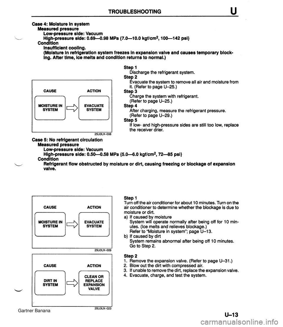
TROUBLESHOOTING Case 4: Moisture in system Measured pressure Low-pressure side: Vacuum High-pressure side: 0.69-4.98 MPa (7.O-lO.O kgf/cm2, 100-1 42 psi) Condition Insufficient cooling. (Moisture in refrigeration system freezes in expansion vaive and causes temporary block- ing. After time, ice melts and condition returns to normal.) CAUSE n MOISTURE IN I SYSTEM le ACTION EVACUATE SYSTEM Step 1 Discharge the refrigerant system. Step 2 Evacuate the system to remove all air and moisture from it. (Refer to page U-25.) Step 3 Charge the system with refrigerant. (Refer to page U-25.) Step 4 After charging, measure the refrigerant pressure. (Refer to page U-29.) Step 5 if low- and high-pressure sides are still too low, replace the receiver drier. Case 5: No refrigerant circulation Measured pressure Low-pressure side: Vacuum ~ighLpressure side: 0.50--0.58 MPa (5.0--6.0 kgf/cm2, 72-45 psi) Condition b Refrigerant flow obstructed by moisture or dirt, causing freezing or blockage of expansion valve. CAUSE ACTION MOISTURE IN CAUSE ACTION Step 1 Turn off the air conditioner for about 10 minutes. Turn on the air conditioner to determine whether the biockage is due to moisture or dirt. a) If caused by moisture System will operate normally after being off for 10 min- utes. (Ice melts and relieves blockage.) Refer to "Moisture in system"; page U-13. b) If caused by dirt System remains abnormal after being off 10 minutes. Go to Step 2. DIRT IN SYSTEM Step 2 1. Remove the expansion valve. (Refer to page U-31.) 2. Blow out the dirt with compressed air. 3. If unable to remove the dirt, replace the expansion valve. 4. Evacuate, charge, and test the system. CLEAN OR REPLACE EXPANSION VALVE Gartner Banana
Page 1079 of 1708

HEATER u Disassembly / Assembly Disassemble and assemble as shown in the figure. 1. Heater core 2. Air mix door 3. Airflow mode door Inspection Heater core 1. Check the heater core fins for blockage. 2. If the fins are clogged, clean them. 3. Check the fittings for cracks or other damage. Replace the heater core if necessary. Gartner Banana
Page 1094 of 1708

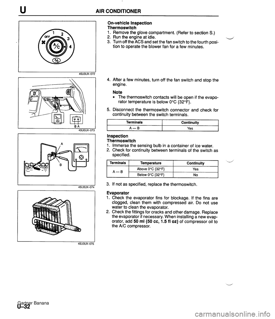
AIR CONDITIONER On-vehicle Inspection Thermoswitch 1. Remove the glove compartment. (Refer to section S.) 2. Run the engine at idle. u 3. Turn off the ACS and set the fan switch to the fourth posi- tion to operate the blower fan for a few minutes. 4. After a few minutes, turn off the fan switch and stop the engine. Note The thermoswitch contacts will be open if the evapo- rator temperature is below 0°C (32°F). 5. Disconnect the thermoswitch connector and check for continuity between the switch terminals. I Terminals I Continuity I I A-B I Yes I - -- Inspection Thermoswitch 1. Immerse the sensing bulb in a container of ice water. 2. Check for continuity between terminals of the switch as specified. 3. If not as specified, replace the thermoswitch. Continuity ( Terminals I Temperature A-B Evaporator 1. Check the evaporator fins for blockage. If the fins are clogged, clean them with compressed air. Do not use water to clean the evaporator. 2. Check the fittings for cracks and other damage. Replace the evaporator if necessary. When installing a new evap- orator, add 50 ml (50 cc, 1.5 fl oz) of compressor oil to the A/C compressor. d Above 0°C {32OFj Below 0°C (32°F) Yes No Gartner Banana
Page 1108 of 1708

u AIR CONDITIONER I NC COMPRESSOR 45UOUX-119 Adjustment Drive belt (With PIS) 1. Loosen PIS oil pump bolts @ and @ and nut 0. ...-' 2. Adjust the belt tension and deflection to specification by turning adjusting bolt 0. 3. Tighten bolts @ and @J and nut 0. (Without PIS) 1. Loosen the locknut. 2. Adjust the belt tension and deflection to specification by Tightening torque: @I: 3246 N.m (3.2-4.7 kgf-m, 24-33 ftelbf) @I: 37-53 Nem (3.7-5.5 kgf-m, 27-39 ft-lbf) 0: 19-25 N.m (1 3-2.6 kgf-m, 14--18 ft-lbf) turning the adjusting bolt. 3. Tighten the locknut. 1 Tension t Deflection when applying moderate pressure 98 N {lo 1 kgf, 22 Ibf) Tightening torque: 38-51 N-m (3.8-5.3 kgf-m, 28-38 ft-lbf) Specification NC COMPRESSOR 45UOUX-121 New 490-588 N (50.0-60.0 kgf, 11 0-1 32 Ibf) 8.0-9.0 mm {0.31-0.35 in) Specification Used 422490 N (43.0-50.0 kgf, 9!5-110 Ibf) 9.0-1 0.0 mm I0.35--0.39 in) New Used Tension Deflection when applying moderate pressure 98 N (10 kgf, 22 Ibf) 490-588 N {50.0-60.0 kgf, 110-132 IbfJ 8.0-9.0 mm i0.31-0.35 in) 422490 N (43.0-50.0 kgf, 95-1 1 0 Ibf) 9.0-1 0.0 mm I0.35-0.39 in) Gartner Banana
Page 1111 of 1708

TECHNICAL DATA TD BP DOHC 0.8-1.4 {0.0324.055) 45.0 (1.772) 46.5 11.831) Engine Item Seat contact width mm {in) Valve spring End gap (Measured in cylinder) mm {in) Seat sinking mm {in) Free length mm {in) Minimum length mm {in) Out-of-square mm {in) Camshaft bearing oil clearance mm {in} Ring groove width in piston mm {in) Standard Maximum Piston ring-to-ring groove clearance mm {in) IN EX IN EX IN EX Standard (No.1-No.5) Maximum 46.26 (1.821) 46.26 (1.821) 39.5 {I 56) with a set load of 224--253 N I22.8-25.8 kgf, 50.2-56.7 Ibf) 39.5 (1 56) with a set load of 224-253 N I22.8-25.8 kgf, 50.2-56.7 Ibf) 1.62 (0.0638) max. 1.62 (0.0638) max. Camshaft 0.035-0.081 {0.0014-0..0031) 0.1 5 (0.006) 0.03 {0.001 2) max. 0.07-0.1 9 {0.002~.0074) 0.20 {0.008) Camshaft runout mm {in) TOP Second Cam height mm {in) Camshaft end play mm (in) 0.15-0.30 {0.006-0.011) 0.15-0.30 {0.006--0.011) -- - I Standard Minimum Standard Minimum Standard (No.1-N0.5) IN EX Standard Maximum Oil (rail) Maximum I 1 .O {0.039) 44.094 {I .7360) 43.894 {I .7281) 44.600 11.7559) 44.400 {I .7480) 25.940-25.965 11.021 3-1.0222) Journal diameter mm Iin) Cylinder block 0.20-0.70 {0.00&0.027) TOD Second Oil 1.52-1 535 {0.0594--0.0604) 1.52-1.54 (0.0599--0.0606} 3.02-3.04 f0.11894.1196) Second Maximum 221.5 (8.720) 0.1 5 {0.006) max. 0.20 {0.008) max. 83.00&83.019 i3.2678-3.2684) 83.25683.263 {3.277&3.2780) 83.508-883.51 3 (3.2877-3.2879) 0.01 9 {0.0007} max. Height mm {in) Distortion mm (in) Grinding mm {in} 0.03-0.07 {0.00124.0027) 0.1 5 {0.006) Cylinder bore diameter mm {in] Standard size 0.25 {0.01) oversize 0.50 (0.02) oversize Piston , Cylinder bore taper and out-of-round mm {in) 82.95442.974 i3.2659--3.2666) 83.211-43.21 7 (3.2761-3.2762) 83.461-83.467 (3.2853--3.2860) 0.0324.059 {0.001 3--0.0023) 0.15 (0.006) Piston diameter Measured at 90" to Pin bore axis and 16.5mm i0.65 in) below oil ring groove mm {in) Standard size 0.25 {0.01) oversize 0.50 (0.02) oversize Piston ring Piston-to-cylinder clearance mm (in) Thickness mm {in) Standard Maximum TOP 1.47-1 -49 (0.0579--0.0586} Second 1.47-1.49 {0.0579--0.0586) Gartner Banana
Page 1118 of 1708

TECHNICAL DATA Mode NOR- MAL 4 POWER - Transmission Item _5 Valve spring specification . , Throttle condition NC4A-EL Control valve Oil pump Drum support Band servo Wide open throttle Outer dia. mm {in) 9.2 (0.362) 6.7 {0.264) 9.0 (0.354) 7.4 (0.291) 8.5 (0.335) 5.5 (0.21 7) 5.0 (0.1971 9.4 (0.370) 11.2 i0.441) 8.9 (0.350) 9.3 (0.366) 6.5 (0.256) 5.5 {0.217) 16.0 (0.630) 27.7 {I .092) 28.25 (1.11 2) 8.0 (0.31 5) - 7.2 (0.283) Half throttle Direct, front, and rear clutches Low and reverse brake Parking rod Shift point (shift s~eed) Pressure modifier - - -- Closed throttle position Kickdown (Wide open throttle) Free length rnm {in) 19.8 (0.780) 17.5 (0.689) 17.5 (0.689) 14.5 (0.571) 21.3 (0.839) 39.5 {I .555) 15.5 {0.610} 19.5 (0.768) 62.0 (2.441) 82.5 (3.248) 43.4 {I .709) 26.8 11.055) 25.7 (1.012) 40.4 (1.591) 47.0 {I .850) 38.7 {I .52) 30.5 {I .20) 5.9-6.2 (0.2324.244) 32.0 {I .260) Throttle backup Wide open throttle Half throttle Small Large Closed throttle position No. of coils 5.3 7.4 5.2 5.0 7.3 24.4 12.0 5.0 21.3 29.7 22.0 14.0 16.5 9.8 14.0 5.4 14.5 - 14.0 N-R reducing Backup control 3-2 control Orifice check 1-2 reducing 1-2 accumulator N-W2-3 accumulator N-D accumulator Throttle relief (ball) Lockup control Fourth gear accumulator Fourth gear 2nd Kickdown (Wide open throttle) Wire dia. mm {in) 0.7 (0.028) 0.7 (0.028) 0.9 (0.035) 0.6 (0.024) 0.9 (0.035) 0.65 (0.026) 0.23 {0.009) 0.8 (0.031) 1.2 t0.047) 1.1 (0.043) 1.4 (0.055) 0.9 (0.035) 0.7 (0.028) 2.6 {0.102) 3.5 (0.1 38) 3.5 (0.1 38) 1.3 (0.051) - 0.7 (0.028) d Shift I D1-+D2 I D2+D3 D3 lockup ON D3+D4 b-+D2 - Vehicle speed kmlh (mph) 58-64 (36-39) 1 OQ108 (62-46) 9&106 (61-65) 152-1 62 (9%100) 3346 (21 -28) D2-*D3 '33434 D4 lockup ON D4-+b 0i-t~~ D2*D3 03 lockup ON D3-D4 58-76 (36-47) 82-1 1 0 (5 1-48} 74-1 00 (46--62) 28-34 (1 7-21 ) 44--55 {2&34) 90-1 08 (5666) 9&106 (61-65) 14-1 64 (87-1 01) Gartner Banana
Page 1119 of 1708

TECHNICAL DATA :em - ange - D - S Transmission Mode NC4A-EL HOLD - POWER HOLD POWER HOLD -ine pressure Vehicle speed kmlh {mph) 27-33 {I 7-20) 3545 {22-27) 152-1 58 (94-97) 12-1 8 (8-1 1) 95-1 05 {59--65) 5-4 (36--39) 1 OO--108 {62--66) 98-1 05 (6 145) 44-55 {28--34) 9&108 {56--67) 94--106 {58--66) 11-17 (7-10) 92-1 00 (5742) 4248 (2629) 99--105 {61-65) 95-1 05 (59-45) 56-62 {35-38) 44-55 (27-34) 96-104 {60-64) 11-17 {7-10) 99-1 05 {61--65) 4248 {26-29) 3541 (21-25) 95--105 (59-65) 775-970 {7.9-9.9, 11 3-1 40) 1,972-2,167 l20.1-22.1,286--314) 285-362 {2.9-3.7,42-52) 795-91 2 (8.1-9.3, 11 61 32) 785-921 (8.G9.4, 114-1 33) 79S912 {8.1-9.3, 116--132) 29!5-392 {3.0-4.0,43-56) 883-1,078 I9.0-11 .O, 128-1 56) 2.1 00-2,500 Throttle condition All positions Wide open throttle Half throttle Closed throttle position Kickdown (Wide open throttle) All positions Wide open throttle Half throttle Closed throttle position Kickdown (Wide open throttle) All positions R range kPa {kgf/cm2, psi) D range kPa {kgf/cm2, psi) S range kPa {kgf/cm2, psi) L range kPa {kgf/cm2, psi) I Shift Dl432 D2-'D3 D443 D3+D1 DS lockup ON s142 s2+s3 S3 lockup ON S142 S2-'s3 S3 lockup ON S3+S1 s3-'s2 s241 s3+s2 S3 lockup ON Ld-2 L14-2 L3+L2 L241 L3-'L2 L2-4-1 L241 L3 lockup ON Idle Stall Idle Stall Idle Stall Idle Stall r~m L. PROPELLER SHAFT Adjusting rod length mm {in) 29.0 {I .14) 29.5 {I. 16) 29.75 (1.1 7) 30.0 {I .18) 30.5 (1.20) 31 .O (1.22) 0.5-0.6 0.75-0.85 'ngine stall speeo Item Max. permissible run-out mm {in) lacuum dia- thragm Time lag Specification 0.4 {0.016) Clearance between body and throttle valve mm {in) Below 25.65 {I ,0099) 25.65-25.15 {I .0099-1.0295) 25.90-26.40 {I ,0197-1.0394) 26.1 5-26.65 (1.0295-1.0492) 26.65--27.15 {I .0492-1.0669) 27.1 5 {1.0689} or over N - D sec. N-R sec. L-' Gartner Banana
Page 1120 of 1708

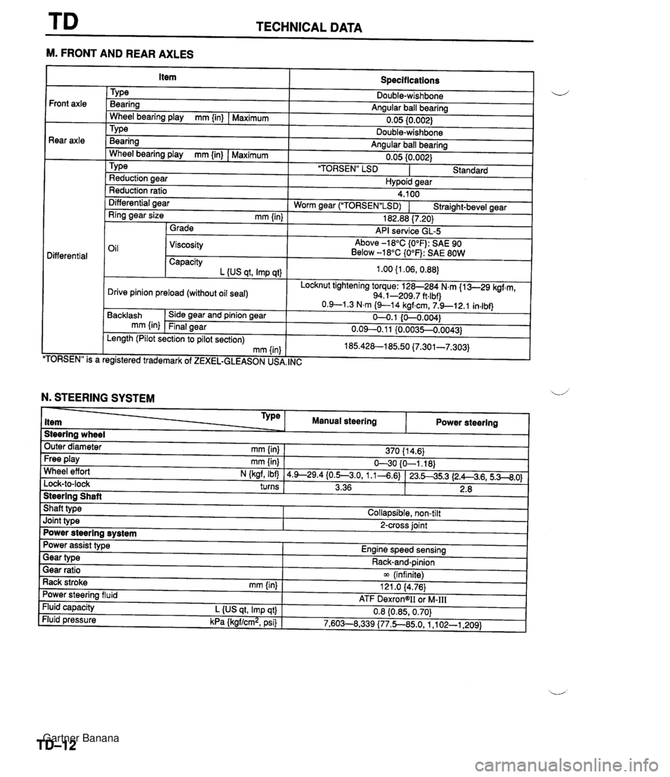
TECHNICAL DATA --- M. FRONT AND REAR AXLES Specifications TY pe Bearing Angular ball bearing 0.05 10.002) Front axle Rear axle - Wheel bearing play mm {in) I Maximum Bearina Anaular ball bearina . .. Wheel bearina plav mm {in) I Maximum " " 0.05 {0.002) 'TORSEN" LSD I Standard TY pe Reduction aear Hvpoid sear Reduction ratio Differential aear 4.100 Worm near ("1ORSEN"LSD) I Straiaht-bevel gear - - Ring gear size mm {in) 1 Grade 182.88 17.201 API service GL-5 Oil 1 Viscosity Above -18°C {O°F): SAE 90 Below -18°C {O°F): SAE 80W Differential Capacity L {US at. Imp at) Locknut tightening torque: 128-284 N.m {I 3-29 kgf.m, 94.1-209.7 ft.lbf) Drive pinion preload (without oil seal) TORSEN" is a Backlash mm {in) . , egistered trademark of ZEXEL-GLEASON US, Side gear and pinion gear Final gear , INC Length (Pilot section to pilot section) mm (in N. STEERING SYSTEM Steering wheel Outer diameter mm {in} 1 370 11 4.6) Type item Free play mm {in) I 630 {O-1.18) Wheel effort N (kaf, Ibfl 14.9--29.4{0.5--3.0, 1.1-4.6) 123.545.3 12.A4.6,5.3--8.0) turns I 3.36 1 2.8 I 1 Manual steering Steering Shaft Shaft type I Collapsible, non-tilt Power steering Joint type I 2-cross joint Power steering system Gear ratio 1 m (infinite) Rack stroke rnm {in) I 121 .O 14.76) Power assist type Engine speed sensing Power steering fluid Fluid capacity L {US qt, Imp qt} Fluid pressure kPa {kgf/cm2, psi) Gear type - - ATF DexrongII oi M-111 0.8 {0.85,0.70) 7,603--8,339 (77.5850, 1 ,I 02-1,209) Rack-and-pinion Gartner Banana