belt MAZDA MX-5 1994 Owner's Guide
[x] Cancel search | Manufacturer: MAZDA, Model Year: 1994, Model line: MX-5, Model: MAZDA MX-5 1994Pages: 1708, PDF Size: 82.34 MB
Page 146 of 1708

WATER PUMP WATER PUMP REMOVAL I INSTALLATION 1. Disconnect the negative battery cable. 2. Drain the engine coolant. (Refer to page E-5 for WARNING and procedure) 3. Remove in the order shown in the figure, referring to Removal Note. 4. Install in the reverse order of removal. 1. Timing belt 4. Water pump Service . . . . . . . . . . . . . . . . . . . . . Section B Inspect for cracks, damaged mounting sur- 2. PIS oil pump face, bearing condition, and leakage. Removal Note . . . . . . . . . . . . . . page E-1 1 If the water pump is damage, replace it. 3. Water hose Do not repair it. 5. Water inlet pipe Gartner Banana
Page 225 of 1708

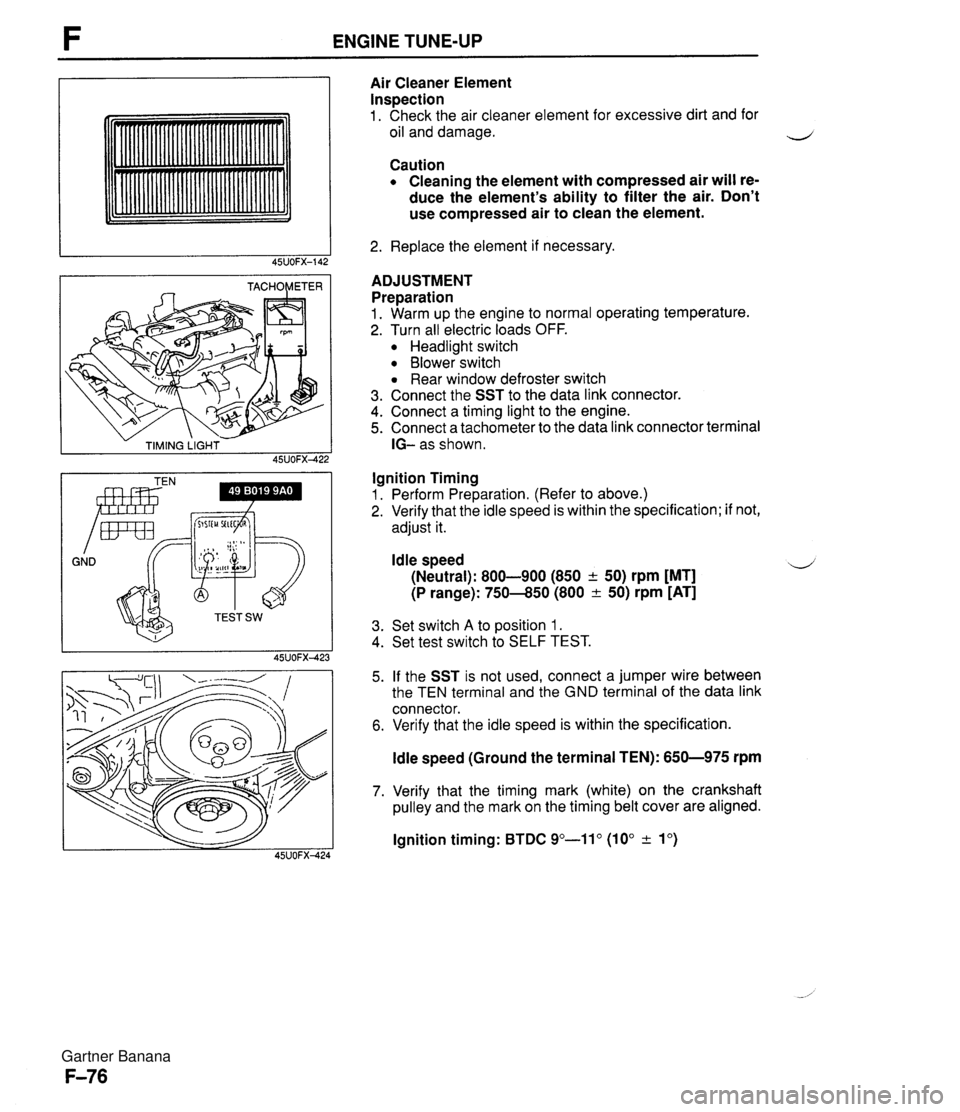
ENGINE TUNE-UP - TIMING LIGHT - 45UOFX422 GND Irnr Air Cleaner Element Inspection 1. Check the air cleaner element for excessive dirt and for oil and damage. Caution Cleaning the element with compressed air will re- duce the element's ability to filter the air. Don't use compressed air to clean the element. 2. Replace the element if necessary. ADJUSTMENT Preparation 1. Warm up the engine to normal operating temperature. 2. Turn all electric loads OFF. Headlight switch Blower switch Rear window defroster switch 3. Connect the SST to the data link connector. 4. Connect a timing light to the engine. 5. Connect a tachometer to the data link connector terminal IG- as shown. Ignition Timing 1. Perform Preparation. (Refer to above.) 2. Verify that the idle speed is within the specification; if not, adjust it. Idle speed 4 (Neutral): 800-900 (850 + 50) rpm [MT] (P range): 750-850 (800 & 50) rpm [AT] 3. Set switch A to position 1. 4. Set test switch to SELF TEST. 5. If the SST is not used, connect a jumper wire between the TEN terminal and the GND terminal of the data link connector. 6. Verify that the idle speed is within the specification. ldle speed (Ground the terminal TEN): 650-975 rpm 7. Verify that the timing mark (white) on the crankshaft pulley and the mark on the timing belt cover are aligned. lgnition timing: BTDC 9"-11" (10" & lo) Gartner Banana
Page 308 of 1708

Before beginning any service procedure. refer to section T of this manual for air bag system service warnings and audio antitheft system alarm conditions . ENGINE ELECTRICAL SYSTEM INDEX ....................................... G- 2 OUTLINE ..................................... G- 3 SPECIFICATIONS ........................... G- 3 TROUBLESHOOTING GUIDE .................. G- 4 CHARGING SYSTEM .......................... G- 6 PREPARATION ............................. G- 6 CIRCUIT DIAGRAM ......................... G- 6 TROUBLESHOOTING ....................... G- 7 BATTERY .................................. G- 8 ALTERNATOR .............................. G-10 DRIVE BELT ................................ G-13 IGNITION SYSTEM ............................ G-15 PREPARATION ............................. G-15 CIRCUIT DIAGRAM ......................... G-15 TROUBLESHOOTING ....................... G-16 IGNITION TIMING ........................... G-17 SPARK PLUG ............................... G-18 IGNITION COIL ............................. G-19 IGNITER ................................... G-19 HIGH-TENSION LEAD ....................... G-20 STARTING SYSTEM ........................... G-21 CIRCUIT DIAGRAM ......................... G-21 TROUBLESHOOTING ....................... G-21 STARTER .................................. G-22 STARTER INTERLOCK SWITCH (MT) ......... G-28 45UOGX401 Gartner Banana
Page 309 of 1708

G INDEX INDEX 1. Battery lnspection . . . . . . . . . . . . . . . . . page G- 8 Recharging . . . . . . . . . . . . . . . . page G- 9 Replacement . . . . . . . . . . . . . . page G-10 2. Alternator Removal / lnstallation . . . . . . . page G-10 Disassembly / Assembly . . . . page G-11 lnspection . . . . . . . . . . . . . . . . . page G-12 3. Drive belt lnspection . . . . . . . . . . . . . . . . . page G-13 Adjustment . . . . . . . . . . . . . . . . page G-14 4. Spark plug Removal / Installation . . . . . . . page G-18 Spark test . . . . . . . . . . . . . . . . . page G-18 lnspection . . . . . . . . . . . . . . . . . page G-18 5. Ignition coil lnspection . . . . . . . . . . . . . . . . . page G-19 Replacement . . . . . . . . . . . . . . page G-19 6. Igniter (in ignition coil) lnspection . . . . . . . . . . . . . . . . . page G-19 7. High-tension lead Removal / lnstallation . . . . . . . page G-20 lnspection . . . . . . . . . . . . . . . . . page G-20 8. Starter Removal / lnstallation . . . . . . . page G-22 Performance lnspection . . . . . page G-23 Disassembly / Assembly . . . . page G24 -' lnspection . . . . . . . . . . . . . . . . . page G26 9. Starter interlock switch (MT) lnspection . . . . . . . . . . . . . . . . . page G-28 Gartner Banana
Page 310 of 1708

OUTLINE OUTLINE SPECIFICATIONS (i.e. powertrain control module (engine), audio, etc.) *2 With System Selector (49 B019 9AO) test switch at SELF TEST. - Engine Item Starter Ignition system Cylinder Arrangement Battery BP DOHC MT I AT 12, Negative ground S46A24L(S) (32 Ah) Maintenance-free 20.0 A.C. I REAR Voltage V Type and capacity (5-hour rate) 12-65 -. 1 2-70 Drive belt deflection mm {in} Dark current" m A Transistorized (built-in voltage regulator) 14.3-1 4.9 21.5 I0.846) 8 (0.31 1 Ignition timing** BTDC ("CA)lrpm U Alternator 'I Dark current is the constant flow of current while the ignition switch is OFF. 45UoGX-003 New Used 101850 Ignition coil Spark plug FRONT 55-7.0 (0.22-0.27) 6.0-7.5 (0.2H.29) 101800 TY pe Primary coil winding n Secondary coil winding kR Type Plug gap mm {in) Firing order Type Output V-A Regulator type Regulated voltage V TY pe Output V-kW Molded (with igniter) - 8.7-1 2.9 (20°C (68°F)) NGK : BKR5E-11 BKR6E-11 (Standard ... MT) NIPPONDENSO : K16PR-U11 K20PR-U11 (Standard ... MT, AT) 1 .O-1.1 IO.040-0.043) 1-3-4--2 Brush length mm {in) Direct 124.95 17.0 i0.67) 11.5 I0.45) Brush length mm {in} Standard Minimum Coaxial reduction 12-1.4 17.5 i0.69) 12.0 i0.47) Standard Minimum Electronic spark advance (ESA) Powertrain control module (engine) controls spark advance Type Spark advance control Gartner Banana
Page 313 of 1708

G CHARGING SYSTEM CHARGING SYSTEM PREPARATION SST T - DIODE TRIO C 49 9200 020 V-ribbed belt tension gauge y-- i BATTERY I - - For inspection of drive belt tension r-7 VOLTAGE REGULATOR L- A 05UOGX-008 CIRCUIT DIAGRAM B TERMINAL I S TERMINAL I Gartner Banana
Page 314 of 1708

CHARGING SYSTEM G TROUBLESHOOTING Check 1 Check if battery p Check battery (Refer to page G-8) J Check 2 I. Turn ignition switch ON Check wire harness 2. Check if voltage exists at each terminal of alternator Check 3 YES 1. Start engine Check alternator (Refer to page G-10) 2. Check if alternator warning light goes off I YES Check if drive belt t Adjust or replace drive belt (Refer to page G-14) 1 YES I Check for dark current (Refer to page G-3) I Check 1 BATTERY r"; Check 3 I ALTERNATOR WARNING LIGHT Check 2 B+: Battery positive voltage I I I B 1 Approx. 12V 1 Approx. 12V I B+ ON ON (Idle) L S 45UOGX-006 OV Approx. 12V Approx. 1V Approx. 12V B+ B+ Gartner Banana
Page 320 of 1708

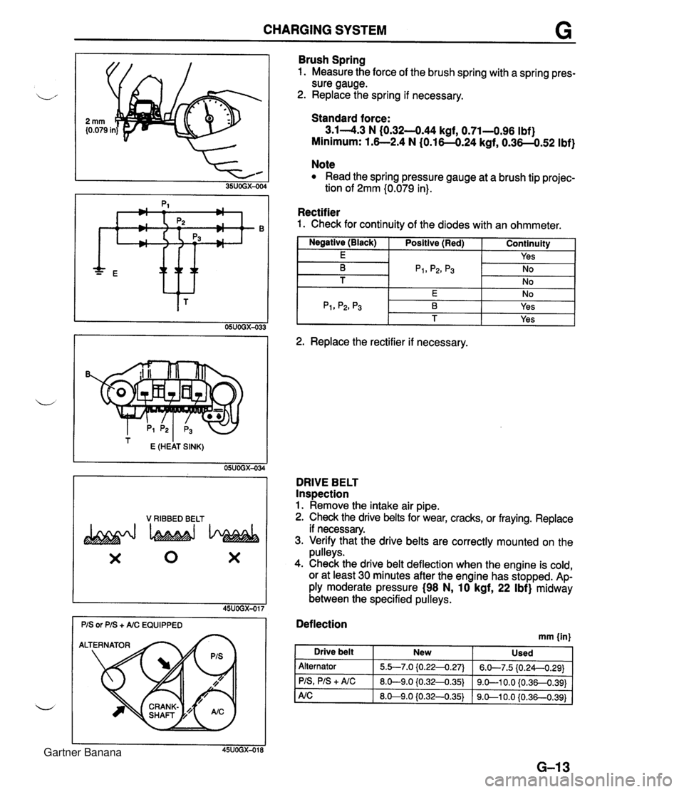
CHARGING SYSTEM G * ttt I E (HEAT SINK) 05UOGX-034 V RIBBED BELT X 0 X Brush Spring 1. Measure the force of the brush spring with a spring pres- sure gauge. 2. Replace the spring if necessary. Standard force: 3.14.3 N (0.32-444 kgf, 0.71-0.96 Ibf) Minimum: 1.6--2.4 N (0.16-0.24 kgf, 0.36-0.52 Ibf) Note Read the spring pressure gauge at a brush tip projec- tion of 2mm (0.079 in). Rectifier 1. Check for continuity of the diodes with an ohmmeter. I Negative (Black) I Positive (Red) I Continuity 1 I E I I Yes I -- 2. Replace the rectifier if necessary. DRIVE BELT Inspection 1. Remove the intake air pipe. 2. Check the drive belts for wear, cracks, or fraying. Replace if necessary. 3. Verify that the drive belts are correctly mounted on the pulleys. 4. Check the drive belt deflection when the engine is cold, or at least 30 minutes after the engine has stopped. Ap- ply moderate pressure (98 N, 10 kgf, 22 Ibf) midway between the specified pulleys. Deflection mm {in) I Drive belt New Used Alternator PIS, PIS + A/C 5.b7.0 {0.224.27) 8.0-9.0 iO.32-0.35) 6.W7.5 (0.24--0.29) 9.0-1 0.0 {0.36-0.391 Gartner Banana
Page 321 of 1708

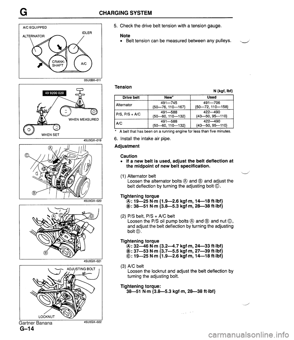
CHARGING SYSTEM I AIC EQUIPPED I WHEN MEASURED 45UOGX-015 - ADJUSTING BOLT I I 5. Check the drive belt tension with a tension gauge. Note Belt tension can be measured between any pulleys. J Tension N {kgf, Ibf) A belt that has been on a ruining engine for less than five minutes. Alternator 'IS
+ A/C 6. Install the intake air pipe. Used Drive belt Adjustment New* I Caution If a new belt is used, adjust the belt deflection at the midpoint of new belt specification. 491-745 (50-76,110-167) 49 1-588 (50-60, 11 0-1 32) d (1) Alternator belt Loosen the alternator bolts @ and @ and adjust the belt deflection by turning the adjusting bolt 0. 491-706 (50-72,110-158) 422490 (43-50,95--110) Tightening torque @: 19-25 N.m (1.9-2.6 kgf.m, 14-1 8 ft4bf) @: 38-51 N.m (3.8-5.3 kgf,m, 28-38 ft-lbf) (2) PIS belt, PIS + AIC belt Loosen the PIS oil pump bolts @ and @ and nut 0, and adjust the belt deflection by turning the adjusting bolt 0. Tightening torque @: 3246 N.m (3.24.7 kgf.m, 24--33 ft4bf) @: 37-53 N.m (3.7-5.5 kgf,m, 27-39 ft-lbf) 0: 19-25 N.m (1.9-2.6 kgf-m, 14-1 8 ft-lbf) (3) AIC belt Loosen the locknut and adjust the belt deflection by turning the adjusting bolt. Tightening torque: 38-51 N.m (3.8-5.3 kgf-m, 28-38 ft-lbf) Gartner Banana
Page 628 of 1708

Before beginning any service procedure. refer to section T of this manual for I air bag system service warnings and audio antitheft system alarm conditions . STEERING SYSTEM INDEX ....................................... N- 2 OUTLINE ..................................... N- 4 SPECIFICATIONS ........................... N- 4 MANUAL STEERING .......................... N- 4 PREPARATION ............................. N- 4 ................ TROUBLESHOOTING GUIDE N- 5 BOOT ...................................... N- 6 STEERING WHEEL AND COLUMN ........... N- 8 ............. STEERING GEAR AND LINKAGE N-12 ENGINE SPEED SENSING POWER STEERING .......................... N-18 PREPARATION ............................. N-18 TROUBLESHOOTING GUIDE ................ N-20 AIR BLEEDING ............................. N-21 POWER STEERING FLUID ................... N-22 STEERING WHEEL AND COLUMN ........... N-24 STEERING GEAR AND LINKAGE ............. N-25 POWER STEERING OIL PUMP ............... N-33 DRIVE BELT ................................ N-37 25UONX-001 Gartner Banana