battery MAZDA MX-5 1994 Repair Manual
[x] Cancel search | Manufacturer: MAZDA, Model Year: 1994, Model line: MX-5, Model: MAZDA MX-5 1994Pages: 1708, PDF Size: 82.34 MB
Page 216 of 1708
![MAZDA MX-5 1994 Repair Manual TROUBLESHOOTING GUIDE TEP 27 INSPECTION KNOCKING ACTION 30 to next step TROUBLESHOOTING HINTS] > AirIFuel mixture too lean @I Incorrect ignition timing (too advance) Fuel injection amount incorrect Q MAZDA MX-5 1994 Repair Manual TROUBLESHOOTING GUIDE TEP 27 INSPECTION KNOCKING ACTION 30 to next step TROUBLESHOOTING HINTS] > AirIFuel mixture too lean @I Incorrect ignition timing (too advance) Fuel injection amount incorrect Q](/img/28/57072/w960_57072-215.png)
TROUBLESHOOTING GUIDE TEP 27 INSPECTION KNOCKING ACTION 30 to next step TROUBLESHOOTING HINTS] > AirIFuel mixture too lean @I Incorrect ignition timing (too advance) Fuel injection amount incorrect Q Overheating Fuel line pressure decreases while accelerating @I Carbon deposits in engine :heck if "00" is displayed on Self-Diagnosis Check- br with ignition switch ON page F-79 Yes Diagnostic Trouble Code No. displayed Check for cause (Refer to specified check sequence) page F-81 "88" flashes Check PCME terminal 1 E voltage uzf page F-145 Specification: Battery positive voltage (Ignition switch ON) 0 If OK, replace PCME page 6143 s If not OK, check wiring between PCME and Self-Diagno- sis Checker page F-7 >heck switches for correct operation with Self- liagnosis Checker Monitor Lamp and ignition ;witch ON as page F-95 SELECT SW A Yes - No Go to next step Lamp not ONIOFF with specified switch Check for cause (Refer to specified check sequence) page F-96 MONl LAMP II- SYSTEM SELECT 1 Lamp always ON Check wiring between PCME terminal 1 D and Self-Diag- nosis Checker uzf page F-7 Zheck if PCME terminal voltages are OK :1R, IT, 2D, 20, and 2Q) page F-146 Yes Go to next step Check for cause (Refer to "Check Point for Each Termi- nal") uzf page F-148 Sheck for correct intake manifold vacuum at idle Yes - No Go to next step Vacuum: More than 450 mmHg (17.7 InHg) VACUUM GAUGE Check for air leakage of intake air system components as page F-100 Check if air cleaner element is clean page F-76 Yes - No Go to next step Replace air cleaner element page F-99 Gartner Banana
Page 218 of 1708
![MAZDA MX-5 1994 Repair Manual TROUBLESHOOTING GUIDE rROUBLESHOOTlNG HINTS] > Poor connection or damaged fuel system or fuel evaporative system 3 Charcoal canister overflow due to fuel evaporative system malfunction 28 INSPECTION C MAZDA MX-5 1994 Repair Manual TROUBLESHOOTING GUIDE rROUBLESHOOTlNG HINTS] > Poor connection or damaged fuel system or fuel evaporative system 3 Charcoal canister overflow due to fuel evaporative system malfunction 28 INSPECTION C](/img/28/57072/w960_57072-217.png)
TROUBLESHOOTING GUIDE rROUBLESHOOTlNG HINTS] > Poor connection or damaged fuel system or fuel evaporative system 3 Charcoal canister overflow due to fuel evaporative system malfunction 28 INSPECTION Check if fuel leak or damage are visible at fuel sys- tem and fuel evaporative system FUEL ODOR ACTION IESCRIPTION I Gasoline odor in cabin Yes Repair or replace page F-107 30 to next step Check if "00" is displayed on Self-Diagnosis Check- er with ignition switch ON page F-79 SELECT SW A SYSTEM SELECT 1 I Yes - No - Yes So to next step Diagnostic Trouble Code No. displayed Check for cause (Refer to specified check sequence) page F-81 "88" flashes Check PCME terminal 1 E voltage page F-145 Specification: Battery positive voltage (Ignition switch ON) o If OK, replace PCME page F-143 o If not OK, check wiring between PCME and Self-Diagno- sis Checker page F-7 Check if vacuum is felt at purge solenoid valve with engine running and throttle valve opened (Neutral switch connector disconnected) Go to Step 5 Check for purge solenoid valve operating sound in this condition o If OK, check vacuum hoses for clogging page F-6 o If not OK, go to next step Apply battery positive voltage and ground to purge solenoid valve and check if air flows through valve Yes Check PCME terminal 2X voltage page F-146 Replace purge solenoid valve @S page F-132 Try known good PCME Daae F-144 Gartner Banana
Page 220 of 1708
![MAZDA MX-5 1994 Repair Manual TROUBLESHOOTING GUIDE F POOR FUEL ECONOMY I [TROUBLESHOOTING HINTS] Nhile fuel consumption is drastically increased during city driving, short-run operation, stop and go driving, extended winterwarm- MAZDA MX-5 1994 Repair Manual TROUBLESHOOTING GUIDE F POOR FUEL ECONOMY I [TROUBLESHOOTING HINTS] Nhile fuel consumption is drastically increased during city driving, short-run operation, stop and go driving, extended winterwarm-](/img/28/57072/w960_57072-219.png)
TROUBLESHOOTING GUIDE F POOR FUEL ECONOMY I [TROUBLESHOOTING HINTS] Nhile fuel consumption is drastically increased during city driving, short-run operation, stop and go driving, extended winterwarm- ~p periods, etc., as opposed to "trip" mileage, an attempt should be made to determine these factors when confronted with "poor mileage" conditions. However, since the operator is not always at fault, the following is offered. 3 Operator depressing accelerator more than usual due to O Alcohol blended fuel used low engine power @ High vehicle load Poor ignition Low tire pressure Low intake air amount Unrecommended tire used Electric spark advance control malfunction Brake dragging Clutch slipping @ Fuel cut control malfunction Exhaust component restricted @ High idle speed AirIFuel mixture too rich High fuel line pressure INSPECTION Check factors other than engine Low tire pressure Section Q Unrecommended tire used @zT Section Q Clutch slipping Section H Brake dragging Section P Exhaust component restricted @zT page F-128 ACTION - Yes Go to next step Repair Check if air hoses are connected correctly @zT page F-99 Yes - No Go to next step Repair @zT page F-99 Check if air cleaner element is clean page F-76 Yes - No Go to next step Replace page 699 Check if "00" is displayed on Self-Diagnosis Check- er with ignition switch ON @zT page F-79 Yes Go to next step SELECT SW A SYSTEM SELECT 1 Diagnostic Trouble Code No. displayed Check for cause (Refer to specified check sequence) page F-81 "88" flashes Check PCME terminal 1 E voltage US page F-145 Specification: Battery positive voltage (Ignition switch ON) 6 If OK, replace PCME page F-143 6 If not OK, check wiring between PCME and Self-Diagno- sis Checker page F-7 Check switches for correct operation with Self- Diagnosis Checker Monitor Lamp and ignition switch ON page F-95 SELECT SW A Yes Go to next step ~~p Lamp not ONIOFF with specified switch Check for cause (Refer to specified check sequence) @zT page F-96 Lamp always ON Check wiring between PCME terminal 1 F and Self-Diag- nosis Checker us page F-7 Gartner Banana
Page 224 of 1708
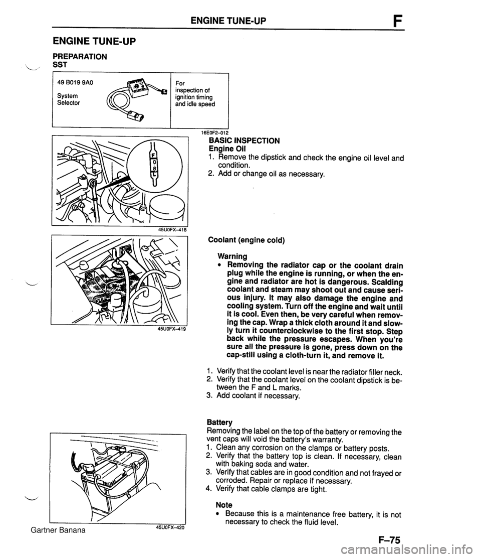
ENGINE TUNE-UP ENGINE TUNE-UP PREPARATION L" SST r I I 16EOF2-012 BASIC INSPECTION Engine Oil 1. Remove the dipstick and check the engine oil level and condition. 2. Add or change oil as necessary. 49 B019 9AO System Selector Coolant (engine cold) For inspection of ignition timing and idle speed Warning Removing the radiator cap or the coolant drain plug while the engine is running, or when the en- gine and radiator are hot is dangerous. Scalding coolant and steam may shoot out and cause seri- ous injury. It may also damage the engine and cooling system. Turn off the engine and wait until it is cool. Even then, be very careful when remov- ing the cap. Wrap a thick cloth around it and slow- ly turn it counterclockwise to the first stop. Step back while the pressure escapes. When you're sure all the pressure is gone, press down on the cap-still using a cloth-turn it, and remove it. 1. Verify that the coolant level is near the radiator filler neck. 2. Verify that the coolant level on the coolant dipstick is be- tween the F and L marks. 3. Add coolant if necessary. Battery Removing the label on the top of the battery or removing the vent caps will void the battery's warranty. 1. Clean any corrosion on the clamps or battery posts. 2. Verify that the battery top is clean. If necessary, clean with baking soda and water. 3. Verify that cables are in good condition and not frayed or corroded. Repair or replace if necessary. 4. Verify that cable clamps are tight. Note Because this is a maintenance free battery, it is not necessary to check the fluid level. Gartner Banana
Page 233 of 1708

F ON-BOARD DIAGNOSIS SYSTEM CODE No. I 03 (SGT SIGNAL) iTEP I INSPECTION ACTION - Yes - No ' I Are there any poor connections in crankshaft posi- tion sensor circuit? Repair or replace connector I Go to next step I 1 Is Code No.04 present at same time? Yes - No Go to next ste~ I GO to Step 5 I Yes - No 3 Go to next step I Is there continuity between crankshaft position sen- sor terminal A and ground? Check for open circuit in wiring from crankshaft position sensor to ground Go to next step Check for open circuit in wiring from crankshaft position sensor to main relay 1 Is there battery positive voltage at crankshaft posi- tion sensor terminal B Yes - No Yes 5 6 Go to next step Is there continuity between crankshaft position sen- sor and PCME? Crankshaft position sensor I PCME C I 2 E Is there approx. 5V at PCME terminal 2E? (With crankshaft position sensor connector discon- nected) Check for open circuit in wiring from crankshaft position sensor to PCME Yes Go to next step I Replace PCME as page 6143 Replace crankshaft position sensor page F-153 Yes - No - 7 Check for short circuit in wiring from crankshaft position sensor to PCME 15UOFX-026 Is there approx. 5V at crankshaft position sensor terminal C? (At harness-side connector with con- nector disconnected) I CODE No. I 04 (SGC SIGNAL) I STEP I INSPECTION 1'1 Are there any poor connections in crankshaft posi- tion sensor circuit? Repair or replace connector Go to next step Go to next step 121 Is Code No.03 also present? Go to Step 5 Go to next step Is there continuity between crankshaft position sen- sor terminal A and ground? Check for open circuit in wiring from crankshaft position sensor to ground Go to next step Check for open circuit in wiring from crankshaft position sensor to main relay 4 Is there continuity between crankshaft position sen- sor and PCME? Go to next step Is there battery positive voltage at crankshaft posi- tion sensor terminal B? Yes - No No - Yes - No 6 Check for open circuit in wiring from crankshaft position sensor to PCME Go to next step Replace PCME page F-143 Crankshaft position sensor I PCME D Replace crankshaft position sensor page F-153 Check for short circuit in wiring from crankshaft position sensor to PCME 2G 7 Is there approx. 5V at PCME terminal 2G? (With crankshaft position sensor connector discon- nected) Is there approx. 5V at crankshaft position sensor terminal D? (At harness-side connector with con- nector disconnected) Yes No Gartner Banana
Page 234 of 1708
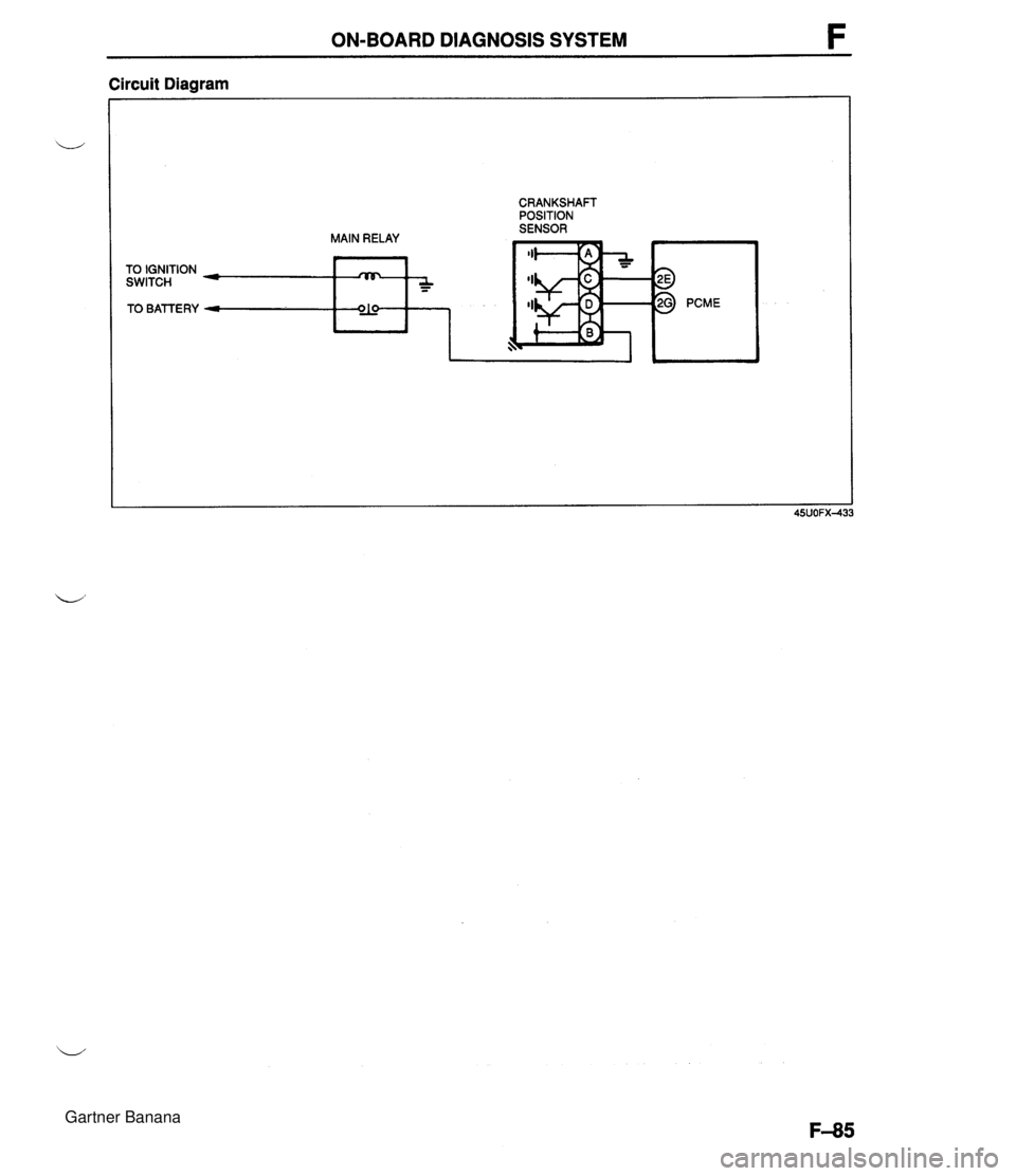
ON-BOARD DIAGNOSIS SYSTEM F Circuit Diagram TO IGNITION SWITCH TO BATTERY MAIN RELAY :AF*, CRANKSHAFT POSITION SENSOR Gartner Banana
Page 240 of 1708
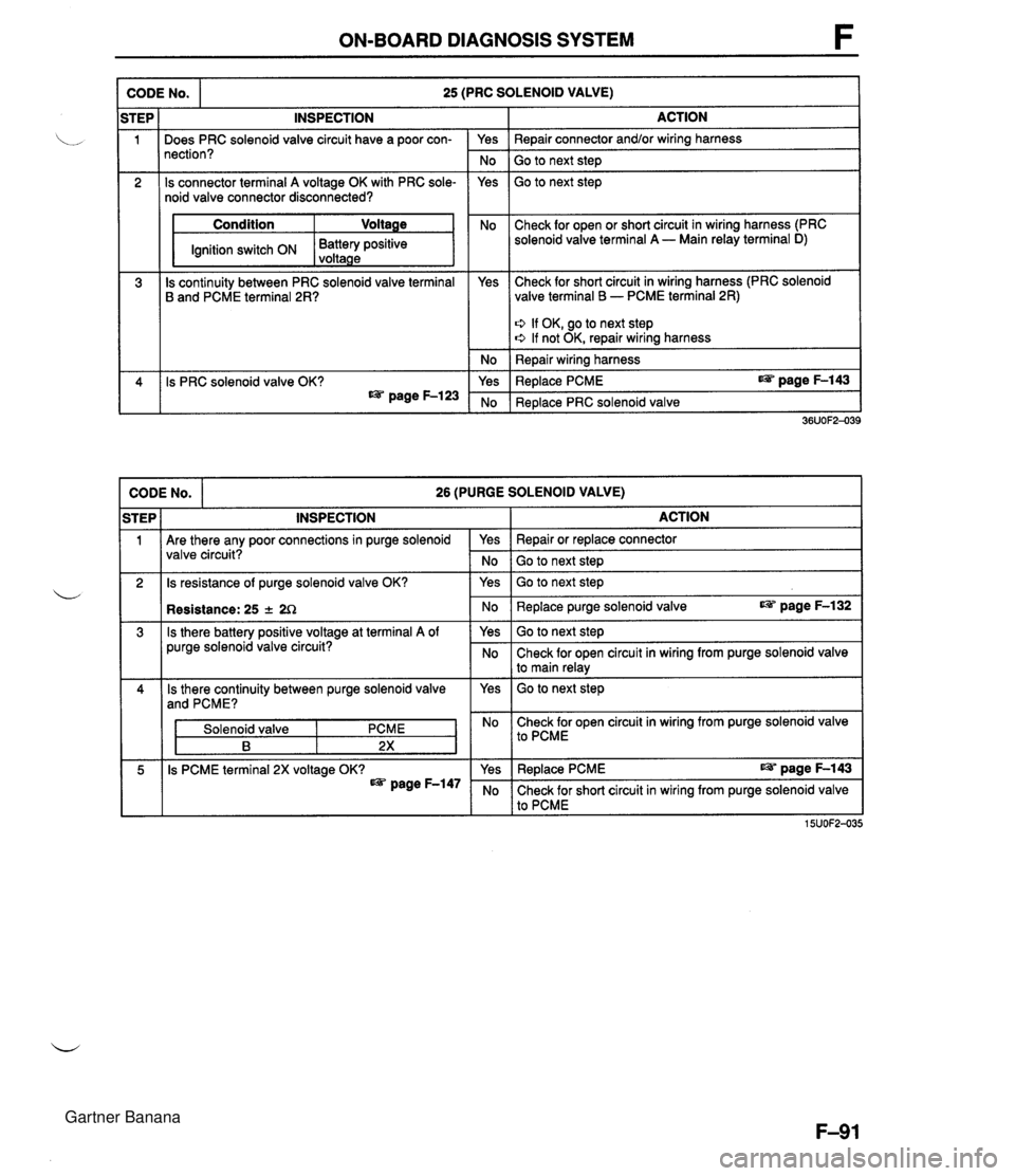
ON-BOARD DIAGNOSIS SYSTEM CODE No. 25 (PRC SOLENOID VALVE) I Condition Ignition switch ON ACTION Repair connector and/or wiring harness Go to next step Go to next step STEP 1 2 Check for open or short circuit in wiring harness (PRC Battery positive solenoid valve terminal A - Main relay terminal D) voltaae 3 CODE No. 26 (PURGE SOLENOID VALVE) iTEP I INSPECTION I ACTION 4 ' I Are there any poor connections in purge solenoid valve circuit? INSPECTION I . - I Is continuity between PRC solenoid valve terminal B and PCME terminal 2R? I 2 Is resistance of purge solenoid valve OK? Does PRC solenoid valve circuit have a poor con- nection? Is connector terminal A voltage OK with PRC sole- noid valve connector disconnected? 36UOF2-039 Is PRC solenoid valve OK? as page F-123 Is there battery positive voltage at terminal A of purge solenoid valve circuit? Yes No Yes Yes Solenoid valve Check for short circuit in wiring harness (PRC solenoid valve terminal B - PCME terminal 2R) No Yes ' No 5 Is PCME terminal 2X voltage OK? page F-147 Q If OK, go to next step e If not OK, repair wiring harness Repair wiring harness Replace PCME page F-143 Replace PRC solenoid valve Yes Repair or replace connector No Go to next step Yes Go to next step No Replace purge solenoid valve page F-132 Yes Go to next step No Check for open circuit in wiring from purge solenoid valve I to main relay I No Check for open circuit in wiring from purge solenoid valve I to PcME I Yes I Replace PCME page F-143 No Check for short circuit in wiring from purge solenoid valve to PCME 15UOF2-035 Gartner Banana
Page 241 of 1708

F ON-BOARD DIAGNOSIS SYSTEM CODE NO. I 28 (EGR SOLENOID VALVE(VACUUM)) I I iTEP I INSPECTION ACTION (vacuum) circuit? valve (vacuum) connector disconnected OK? - Yes Repair or replace connector I Go to next step Yes Go to next step No - Yes - No 3 Check for open or short circuit in wiring from EGR solenoid valve (vacuum) terminal A to main relay terminal I Condition 1 Voltage IG switch ON I Battery positive voltage Is continuity between EGR solenoid valve (vacu- um) terminal B and PCME terminal IT OK? Check for short circuit in wiring from EGR solenoid valve (vacuum) terminal B to PCME terminal IT 0 If OK, go to next step 0 If not OK, repair or replace wiring harness Repair or replace wire harness Yes - No 4 Replace PCME Replace EGR solenoid valve (vacuum) Is EGR solenoid valve (vacuum) OK? CODE No. I - 29 (EGR SOLENOID VALVE(VENT)) I iTEP I INSPECTION ACTION I I If there a poor connection in EGR solenoid valve (vent) circuit? Repair or replace connector Go to next step Go to next step 1 Is connector terminal A voltages with EGR solenoid valve (vent) connector disconnected OK? Check for open or short circuit in wiring from EGR solenoid valve (vent) terminal A to main relay terminal I Condition I Voltage G switch ON I Battery positive voltage 1 Yes 3 Check for short circuit in wiring from EGR solenoid valve (vent) terminal B to PCME terminal 1 R Is continuity between EGR solenoid valve (vent) terminal B and PCME terminal 1 R OK? 0 If OK, go to next step s If not OK, repair or replace wiring harness Re~air or reolace wire harness I 4 Replace PCME I Replace EGR solenoid valve (vent) 39UOFX-110 Is EGR solenoid valve (vent) OK? No Yes No Gartner Banana
Page 242 of 1708
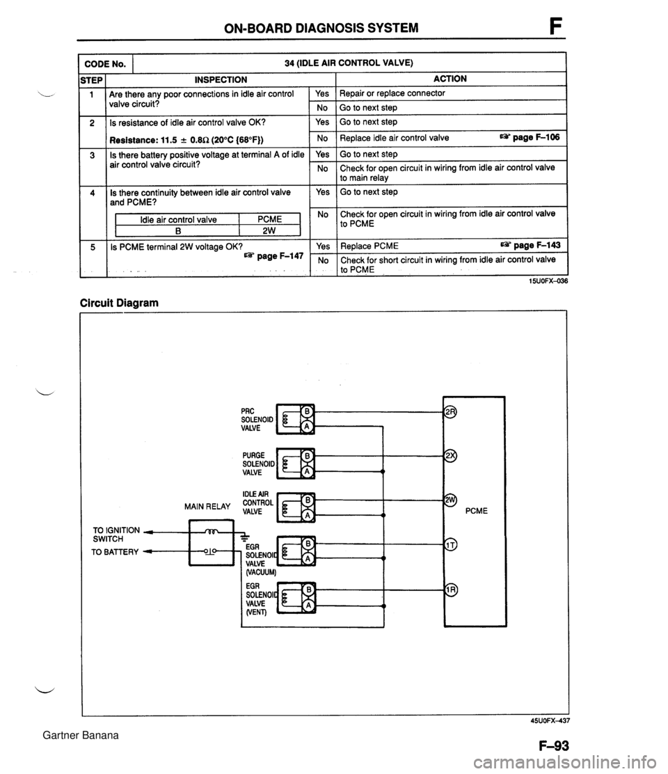
ON-BOARD DIAGNOSIS SYSTEM INSPECTION Are there any poor connections in idle air control valve circuit? CODE NO. Is resistance of idle air control valve OK? 34 (IDLE AIR CONTROL VALVE) 1 Resistance: 11.5 + 0.8R (20°C (68°F)) Is there battery positive voltage at terminal A of idle air control valve circuit? Is there continuity between idle air control valve and PCME? Idle air control valve I PCME B 2W Is PCME terminal 2W voltage OK? page F-147 Circuit Diagram No 1 Go to next ste~ I Yes ACTION Repair or replace connector Yes No Yes Go to next step I I Go to next step Replace idle air control valve page F-106 Yes No No Check for open circuit in wiring from idle air control valve I to PCME Go to next step Check for open circuit in wiring from idle air control valve to main relay SOLENOID VALVE pRc c Yes No PURGE SOLENOID VALVE Replace PCME page F-143 Check for short circuit in wiring from idle air control valve to PCME t PCME 15UOFX-036 TO IGNITION - rVF, SWITCH A - - EGR TO BATTERY - O?! SOLENOIC t 4 I, VALVE (VACUUM) SOLENOI VALVE (VENT) Gartner Banana
Page 243 of 1708
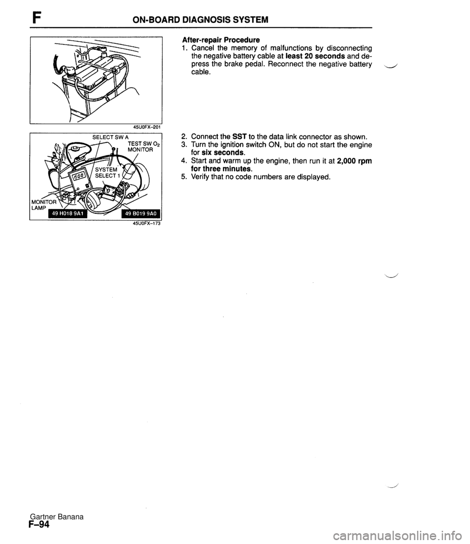
ON-BOARD DIAGNOSIS SYSTEM SELECT SW A Af ter-repair Procedure 1. Cancel the memory of malfunctions by disconnecting the negative battery cable at least 20 seconds and de- press the brake pedal. Reconnect the negative battery cable. 2. Connect the SST to the data link connector as shown. 3. Turn the ignition switch ON, but do not start the engine for six seconds. 4. Start and warm up the engine, then run it at 2,000 rpm for three minutes. 5. Verify that no code numbers are displayed. Gartner Banana