battery MAZDA MX-5 1994 Owner's Manual
[x] Cancel search | Manufacturer: MAZDA, Model Year: 1994, Model line: MX-5, Model: MAZDA MX-5 1994Pages: 1708, PDF Size: 82.34 MB
Page 130 of 1708

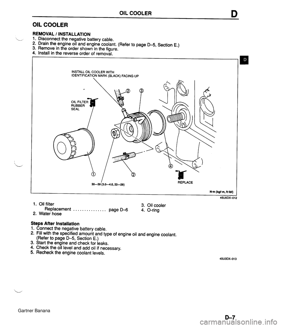
OIL COOLER D OIL COOLER REMOVAL I INSTALLATION 1. Disconnect the negative battery cable. 2. Drain the engine oil and engine coolant. (Refer to page D-5, Section E.) 3. Remove in the order shown in the figure. 4. Install in the reverse order of removal. INSTALL OIL COOLER WITH IDENTIFICATION MARK (BLACK) FACING UP A OIL FILTER^ RUBBER I 3049 (3.0--4.0,22-28) REPLACE Nm {kgtm, ft4bf) 1. Oil filter 3. Oil cooler Replacement . . . . . . . . . . . . . . . Page D-6 4. O-ring 2. Water hose Steps After Installation 1. Connect the negative battery cable. 2. Fill with the specified amount and type of engine oil and engine coolant. (Refer to page D-5, Section E.) 3. Start the engine and check for leaks. 4. Check the oil level and add oil if necessary. 5. Recheck the engine coolant levels. Gartner Banana
Page 131 of 1708

D OIL PAN OIL PAN REMOVAL / INSTALLATION 1. Disconnect the negative battery cable. 2. Drain the engine oil. (Refer to page D-5.) 3. Remove the undercover. 4. Remove in the order shown in the figure, referring to Removal Note. 5. Install in the reverse order of removal, referring to Installation Note. 94--117 (9.5-11.9,69-86) 57-78 (5.8--8.0,42-57) 69-83 {7.0-8.5,51-61) GASKET, REPLAC 7.9--10.7 Nm {60-110 kgfan, 70-95 O-RING, REPLACE 'If 64-49 (6.!%9.1,4&65) 7.9-10.7 N.m (80-110 kgf.crn, 70-95 indbf] 1. Dipstick and pipe 5. Oil pan ............. 2. Intermediate shaft Removal Note page D- 9 ........... .......... Removal / lnstllation section N Installation Note page D-10 3. Engine mount nut 6. Oil strainer 7. Oil baffle ,' ............. Removal Note page D- 9 ............. 4. Crossmember installation bolt and nut Removal Note page D- 9 ............. ........... Removal Note page D- 9 Installation Note page D- 9 Gartner Banana
Page 133 of 1708

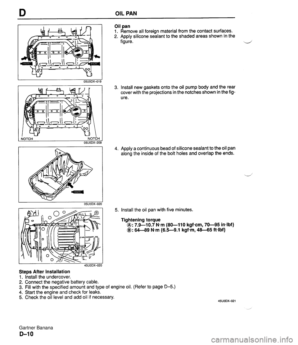
OIL PAN NOTCH NOTCH I 05UODX-209 Steps After Installation 1. Install the undercover. Oil pan 1. Remove all foreign material from the contact surfaces. 2. Apply silicone sealant to the shaded areas shown in the figure. 3. Install new gaskets onto the oil pump body and the rear cover with the projections in the notches shown in the fig- ure. 4. Apply a continuous bead of silicone sealant to the oil pan along the inside of the bolt holes and overlap the ends. 5. Install the oil pan with five minutes. Tightening torque 0: 7.9-10.7 N.m (80-110 kgf-cm, 70-95 in4bf) @: 64-49 N.m (6.5-9.1 kgf-m, 48-45 ft-lbf) 2. Connect the negative battery cable. 3. Fill with the specified amount and type of engine oil. (Refer to page D-5.) 4. Start the engine and check for leaks. 5. Check the oil level and add oil if necessary. Gartner Banana
Page 144 of 1708

RADIATOR RADIATOR REMOVAL I INSTALLATION 1. Disconnect the negative battery cable. 2. Drain the engine coolant. (Refer to page E-5 for WARNING and procedure.) 3. Remove the undercover. 4. Remove in the order shown in the figure. 5. Install in the reverse order of removal. 1. Air intake pipe 5. Coolant fan, condenser fan 2. Radiator hose 6. Radiator 3. Coolant reservoir hose Inspection . . . . . . . . . . . . . . . . . . . . . . below 4. Coolant fan motor connector, condenser fan motor connector INSPECTION Check for the following and repair or replace as necessary. 1. Cracks, damage, and water leakage. 2. Bent fins (repair with a screwdriver). 3. Distorted or bent radiator inlet. Steps After Installation 1. Install the undercover. _i 2. Connect the negative battery cable. 3. Fill the radiator with coolant. (Refer to page E-6 for WARNING and procedure.) Gartner Banana
Page 145 of 1708

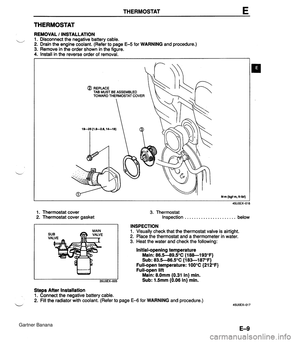
THERMOSTAT E THERMOSTAT REMOVAL / INSTALLATION u 1. Disconnect the negative battery cable. 2. Drain the engine coolant. (Refer to page E-5 for WARNING and procedure.) 3. Remove in the order shown in the figure. 4. Install in the reverse order of removal. @) REPLACE TAB MUST BE ASSEMBLED TOWARD THERMOSTAT COVER 1. Thermostat cover 3. Thermostat 2. Thermostat cover gasket Inspection . . . . . . . . . . . . . . . . . . . . . . below INSPECTION 1. Visually check that the thermostat valve is airtight. 2. Place the thermostat and a thermometer in water. 3. Heat the water and check the following: Initial-opening temperature Main: 86.5-89.S°C (1 88--193OF) Sub: 83.5--86.S°C (1 8Sl87OF) Full-open temperature: 100°C (21 2°F) Full-open lift Main: 8.0mm 10.31 in) min. Sub: 1.5mm (0.06 in) min. Steps After installation 1. Connect the negative battery cable. 2. Fill the radiator with coolant. (Refer to page €4 for WARNING and procedure.) u Gartner Banana
Page 146 of 1708

WATER PUMP WATER PUMP REMOVAL I INSTALLATION 1. Disconnect the negative battery cable. 2. Drain the engine coolant. (Refer to page E-5 for WARNING and procedure) 3. Remove in the order shown in the figure, referring to Removal Note. 4. Install in the reverse order of removal. 1. Timing belt 4. Water pump Service . . . . . . . . . . . . . . . . . . . . . Section B Inspect for cracks, damaged mounting sur- 2. PIS oil pump face, bearing condition, and leakage. Removal Note . . . . . . . . . . . . . . page E-1 1 If the water pump is damage, replace it. 3. Water hose Do not repair it. 5. Water inlet pipe Gartner Banana
Page 148 of 1708

COOLANT FAN MOTOR , 45UOEX-022 REPLACEMENT 1. Disconnect the negative battery cable. 2. Remove in the order shown in the figure. 3. Install in the reverse order of removal. COOLANT FAN MOTOR INSPECTION 1. Check that the battery is fully charged. 2. Disconnect the coolant fan motor connector. 3. Connect the battery and an ammeter to the coolant fan motor connector. 4. Verify that current is as specified. Current: below 7.7A 5. If current is not within specification and/or the coolant fan does not turn smoothly, replace the coolant fan motor. 45UOEX-023 1. Air intake pipe 4. Coolant fan motor 2. Coolant fan motor connector 5. Coolant fan cowling 3. Coolant fan Gartner Banana
Page 149 of 1708

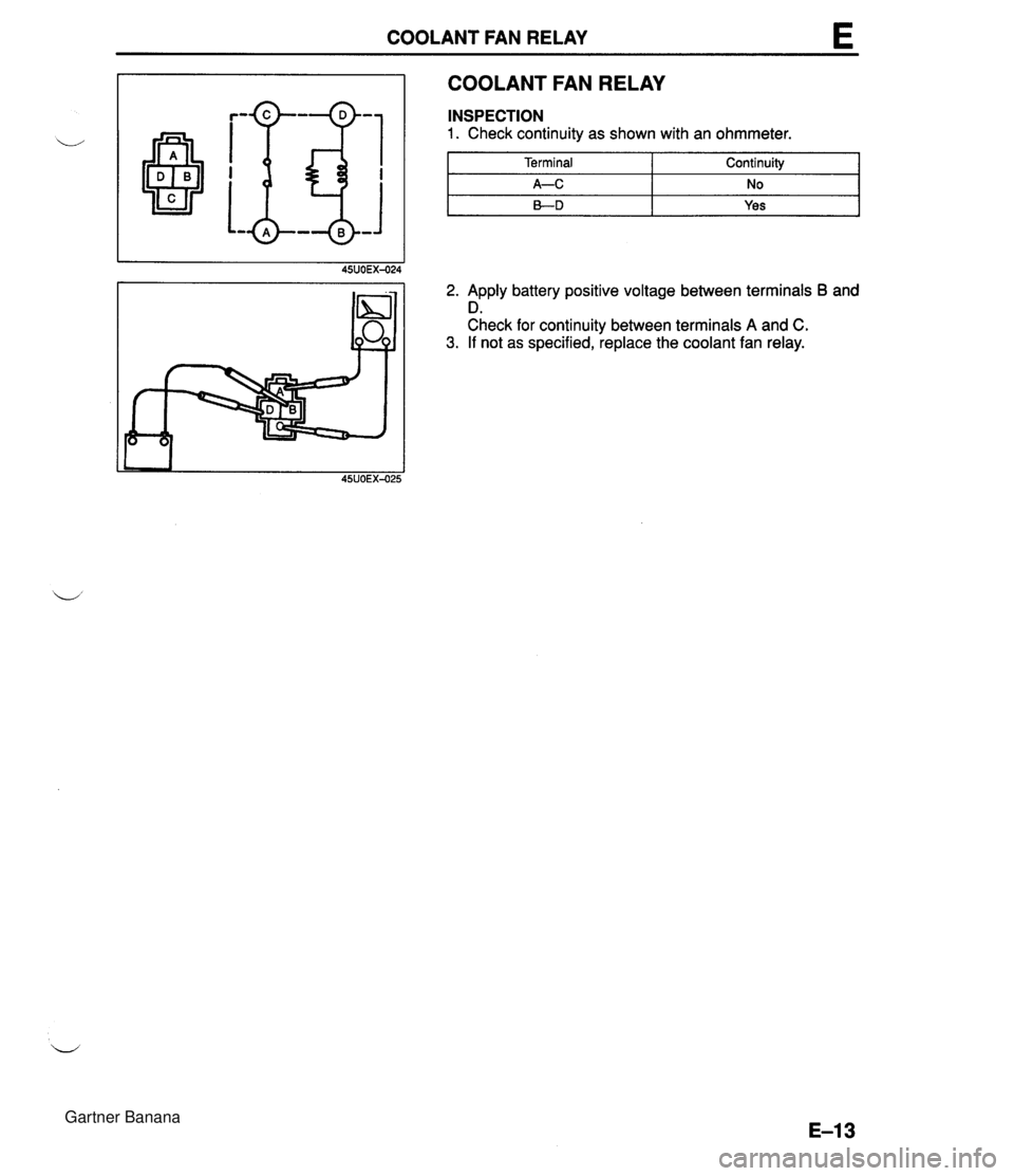
COOLANT FAN RELAY COOLANT FAN RELAY 2. Apply battery positive voltage between terminals B and D. Check for continuity between terminals A and C. 3. If not as specified, replace the coolant fan relay. 45UOEX-025 INSPECTION 1. Check continuity as shown with an ohmmeter. Terminal A-C B-D Continuity NO Yes Gartner Banana
Page 163 of 1708

F TROUBLESHOOTING GUIDE Troubleshooting chart F TROUBLESHOOTING GUIDE 7 I - page F-79 CRANKS NORMALLY BUT HARD TO START - AFTER WARM-UP 1 Check if PCME terminal voltaoes are OK Check If '00" is displayed on Sell-Diagnosis Check- er wilh lonillon switch ON I (2D* 2R and *) page 6145 'SCRIPTION Enginecranks at normal speed but requires excessive cranking time (more than 5 sec.) before starting after run- ning and hot soaked Battery In normal condition Engine starts normally when cold TROUBLESHOOTING HINTS] D AidFuel mixture too rich @ Vapor lock Fuel injection control malfunction . Fuel pressure not held In fuel line after engine stop Fuel injector fuel leakage . High RVP (winter) fuel used In warm weather ITEP I INSPECTlON Yes "88" flashes I Check PCME terminal I E ~Itg " p8gO F-I45 1 ACVON Go to next slep No Speclflcatlon: Baltery porltlve voltage (Ignition rwltch 1 ON) Diagnostic Trouble Code No. dlrplayed Check lor cause (Refer lo specified check sequence) a page F-81 If OK, replace PCME rr F-143 I:, if not OK, check wiring between PCME and Sell-Diagno- sis Checker LQ page M I No Check for cause (Refer to 'Check Pdnt for Each Terml- nal') page F-1 I -- ~ Yes Go lo next step I p- / Yes DESCRIPTION: Further describes the symptom. Confirm that the chart addresses the actual symptom before beginning troubleshooting. Go to next slep TROUBLESHOOTING HINTS: This describes the possible point of malfunction. STEP: This shows the order of troubleshooting. Proceed with troubleshooting as indicated. INSPECTION: This describes an inspection to quickly determine the malfunction of parts. If a detailed procedure is nec- essary to perform the INSPECTION, refer to the page shown by the "UW' mark. ACTION: This recommends the appropriate action to take as a result (YesINo) of the INSPECTION. How to per- form the action is described on the reference page shown by the "=" mark. Gartner Banana
Page 166 of 1708

TROUBLESHOOTING GUIDE SYMPTOM TROUBLESHOOTING 2 CRANKS NORMALLY BUT WILL NOT START (NO COMBUSTION) Engine cranks at normal speed but shows no sign of "firing" ESCwPTION : Battery in normal condition Throttle valve not held wide open throttle while cranking Fuel in tank rROUBLESHOOTlNG HINTS] ecause of no combustion, possibly no fuel is injected to engine or no ignition at all cylinders 1 No spark O Low fuel line pressure lanition control malfunction @ Low engine compression ignition system component malfunction I No fuel injection Fuel pump does not operate Fuel injector does not operate INSPECTION ACTION :heck if strong blue spark is visible at disconnected iigh-tension lead while cranking engine :heck if "00" is displayed on Self Diagnosis Checker ~ith ignition switch ON page F-79 Sonnect data link connector terminals F/P and GND ~ith jumper wire and check for fuel pump operating sound with ignition switch ON page F-114 Yes - No - Yes No - Yes - No Go to Step 3 Go to Step 2 Check ignition system (Refer to Troubleshooting "Misfire") mf Section G Diagnostic Trouble Code No. displayed Check for cause (Refer to specified check sequence) page F-81 "88" flashes Check PCME terminal 1 E voltage ojg. page F-145 Specification: Battery positive voltage (Ignition switch ON) 0 If OK, replace PCME us? page F-143 Q If not OK, check wiring between PCME and Self-Diagno- sis Checker page F-7 Check if engine starts in this condition 0 If starts, check fuel pump relay f@ page F-117 r3 If does not start, go to Step 5 Go to Step 4 Gartner Banana