alternator MAZDA MX-5 1994 Workshop Manual
[x] Cancel search | Manufacturer: MAZDA, Model Year: 1994, Model line: MX-5, Model: MAZDA MX-5 1994Pages: 1708, PDF Size: 82.34 MB
Page 10 of 1708

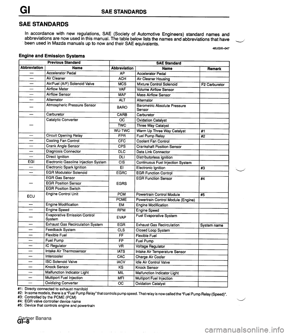
SAE STANDARDS SAE STANDARDS In accordance with new regulations, SAE (Society of Automotive Engineers) standard names and abbreviations are now used in this manual. The table below lists the names and abbreviations that have 4 been used in Mazda manuals up to now and their SAE equivalents. 46UGIX-047 Engine and Emission Systems Accelerator Pedal Air Cleaner Housing I Mixture Control Solenoid I F2 Carburetor ] Abbreviation AP ACH MCS VAF M AF Abbreviation - - - - - Volume Airflow Sensor I I Name Accelerator Pedal Air Cleaner AirlFuel (NF) Solenoid Valve Airflow Meter Airflow Sensor I Mass Airflow Sensor I I Alternator I I - - - -~ I Barometric Absolute Pressure I I Sensor I I Alternator Atmospheric Pressure Sensor I - 1 Carburetor CARB 1 Catalytic Converter OC ALT BAR0 Carburetor 1 Oxidation Catalvst I - - - - - I Direct Ignition I DL1 EG I 1 Electronic Gasoline lniection Svstem I CIS Three Way Catalyst Warm Up Three Way Catalyst Fuel Pump Relay Coolant Fan Control Crankshaft Position Sensor Data Link Connector Circuit Opening Relay Cooling Fan Control Crank Angle Sensor Diaanosis Connector Distributorless Ignition I Continuous Fuel lniection Svstem I 1 #1 #2 FPR C FC CPS DLC I Previous Standard SAE Standard Name I Remark - ( Electronic Spark Ignition EGR Gas Sensor EGR Position Sensor EGR Position Switch El Electronic Ignition 1 #3 EGR Function Control I - I EGR Modulator Solenoid I EGRC 4 ECU I Evaporative Emission Control Svstem I EVAP - - I -,--- I - I Exhaust Gas Recirculation System I EGR Engine Control Unit PCM PCME Engine Modification Ennine Speed EM RPM - - - - - Feedback System Flexible Fuel - I Intercooler Powertrain Control Module I #5 I EGR Function Sensor CLS FF Fuel Pump IC Regulator Intake Air Thermosensor CAC I Powertrain Control Module (Engine) I #4 FP VR IATS - I ISC Solenoid Valve I IACV Engine Modification I Engine Speed - Fuel Evaporative System I Exhaust Gas Recirculation 1 System name 1 Closed Loop System I Flexible Fuel Knock Sensor I I - ( Knock Sensor I KS I Malfunction Indicator Light I I - I Malfunction Indicator Liaht MIL Multiport Fuel Injection Oxidation Catalyst - 1 Multiport Fuel Injection #1: Directy connected to exhaust manifold #2: In some models, there is a "Fuel Pump Relay" that controls pump speed. That relay is now called the 'Fuel Pump Relay (Speed)". #3: Controlled by the PCME (PCM) 4 #4: EGR valve controller device name #5: Device that controls engine and powertrain MFI - 1 Oxidizina Converter OC Gartner Banana
Page 39 of 1708

B INDEX INDEX 1. Timing belt Removal / Installation ....... page 8-1 2 2. Cylinder head gasket Replacement .............. page 6-1 6 3. HLA Removal / Installation ....... page 8-20 4. Front oil seal Replacement .............. page 6-24 5. Rear oil seal Replacement .............. page 6-26 INTAKE MANIFOLD COMPRESSION INSPECTION, PAGE B-10 TIGHTENING TORQUE STANDARD: 1,255 kPa (1 2.8 k f/cm2, 182 psi)-300 rpm 19-25 Nm (1.9-2.6 kgfq 14--18 ft4bf) MINIMUM: 883 kPa (9.0 kgflcm 9 , 128 psi}-300 rpm TIGHTENING TORQUE 3946 Nm i3.9--4.7 kgf m, 29-33 ftdbf) DRIVE BELT ADJUSTMENT. PAG ENGINE OIL INSPECTION, SERVICE, SECTION D DEFLECTION mm (in) ENGINE COOLANT INSPECTION, 6. Engine Removal .................. page 8-28 Engine stand mounting ..... page 6-32 Disassembly .............. page 6-35 Inspection / Repair ......... page B-47 Assembly ................. page 559 Engine stand dismounting ... page 8-81 , Installation ................ page B-83 SERVICE, SECTION E DRIVE BELT ALTERNATOR PIS. PIS + AlC AlC NEW 55-7.0 (0.224.27) 8.&9.0{0.324.35] 8.0-9.0{0.324.35) USED 6.0-7.5 (0.24-0.29) 9.0-10.0{0.364.39) 9.0-10.0{0.364.39} LIMIT 8.0 (0.31) 11.5 (0.45) 11.5 (0.453 Gartner Banana
Page 41 of 1708

B TROUBLESHOOTING GUIDE Problem nsufficlent power 4bnormal combustion Engine noise Possible Cause Insufficient compression Malfunction of HLA' Compression leakage from valve seat Seized valve stem Weak or broken valve spring Failed cylinder head gasket Cracked or distorted cylinder head Stuck, damaged, or worn piston ring Cracked or worn piston Malfunction of fuel system Malfunction of ignition system Others Slipping clutch Dragging brakes Wrong size tires Malfunction of engine-related components Malfunction of HLA* Stuck or burned valve Weak or broken valve spring Carbon accumulation in combustion chamber Malfunction of fuel system Malfunction of ignition system Crankshaft- or bearing-related parts Excessive main bearing oil clearance Main bearing seized or heat-damaged Excessive crankshaft end play Excessive connecting rod bearing oil clearance Connecting rod bearing seized or heat-damaged Piston-related parts Worn cylinder Worn piston or piston pin Seized piston Damaged piston ring Bent connecting rod Valves or timing-related parts Malfunction of HLA' Broken valve spring Excessive valve auide clearance Malfunction of cooling system Malfunction of fuel system Others Malfunction of water pump bearing Improper drive belt tension Malfunction of alternator bearing Exhaust gas leakage Malfunction of timina belt tensioner Remedy Replace Repair Replace Replace Replace Replace Replace Replace Refer to section F Refer to section G Refer to section H Refer to section P Refer to section Q Replace Replace Replace Eliminate carbon Refer to section F Refer to section G Replace or repair Replace Replace or repair Replace or repair Replace Replace or repair Replace Replace Replace Replace Replace Replace Replace Refer to section E Refer to section F Refer to section E Adjust Refer to section G Refer to section F Replace Page Tappet noise may occur if the engine has set idle for an extended period. The noise should dissipate after the engine has reached normal operating temperature. (HLA troubleshooting: Refer to page 6-8) Gartner Banana
Page 43 of 1708

ENGINE TUNE-UP V-RIBBED BELT PIS or PIS + A/C EQUIPPED AIC EQUIPPED IDLER Coolant quality 1. Verify that there is no buildup of rust or scale around the radiator cap or radiator filler neck. 2. Verify that the coolant is free of oil. d 3. Replace the coolant if necessary. DRIVE BELT Inspection 1. Remove the air intake pipe. 2. Check the drive belts for wear, cracks, and fraying. Re- place if necessary. 3. Verify that the drive belts are correctly mounted on the pulleys. 4. Check the drive belt deflection when the engine is cold, or at least 30 minutes after the engine has stopped. Ap- ply moderate pressure 98 N (10 kgf, 22 Ibf) midway be- tween the specified pulleys. Deflection rnrn {in) Drive belt New' Used Limit Alternator 5.5-7.0 6.0-7.5 m.22-0.27) (0.24-0.29) 8.0 (0.31) t" NC 8.0-9.0 9'0-'0.0 11.5 {0.45} {0.32-0.35) {0.36-0.39) A belt that has been on a running engine for less than five minutes. 5. If the deflection is not within specification, adjust it. 6. Install the air intake pipe. Drive belt tension check Belt tension can be checked in place of belt deflection. Check the drive belt tension when the engine is cold, or at least 30 minutes after the engine has stopped. Using the SST, check the belt tension between any two pulleys. Gartner Banana
Page 44 of 1708

ENGINE TUNE-UP B 2 ADJUSTING BOLT LOCKNUT Tension N {kgf, lbfl I Drive belt New* Used I Limit I A belt that has been on a running engine for less than five minutes. 45UOBX-011 Alternator PIS, PIS + A/C AIC Adjustment (1) Alternator belt Loosen the alternator bolts @J and @ and adjust the belt deflection by turning the adjusting bolt 0. Tightening torque @: 19-25 N-m {I .9-2.6 kgf.m, 14-18 ft4bf) @: 38-51 N-m (3.8-5.3 kgf.m, 28-38 ft4bf) 491 -745 (50-76, 11 0-1 67) 491-588 (50-60, 11C-132) 49 1-588 (50-60, 11 0-1 32) (2) PIS belt, PIS + A/C belt Loosen the PIS oil pump bolt @ and nuts @ and @ and adjust the belt deflection by turning the adjusting bolt @. Tightening torque @: 3246 N.m (3.24.7 kgf.m, 24-33 ftlbf) @: 37-53 N-m I3.7-5.5 kgf.m, 27-39 ft4bf) 0: 19-25 N-m {I .9-2.6 kgf.m, 14-18 ft4bf) 491 -706 (50-72, 11 0-1 58) 422-490 (43-50, 95-1 10) 422490 {43-50, 95-1 lo} (3) AIC belt If necessary, loosen the lock nut and adjust the belt deflection by turning the adjusting bolt. 343 (35,771 245 {25, 55) 245 {25,55) Tightening torque: 38-51 N.m (3.8-5.3 kgf.m, 28-38 ft.lbf) Gartner Banana
Page 49 of 1708

B ON-VEHICLE MAINTENANCE TIMING BELT Removal / lnstallation 1. Disconnect the negative battery cable. 2. Drain the engine coolant. 3. Remove the under cover. 4. Remove in the order shown in the figure, referring to Removal Note. 5. Install in the reverse order of removal, referring to lnstallation Note. (80-110 kgfmn, 7.9-10.7 Nm 13-17 Nm (125-175 kgfcm, 109-151 In4bf) Nm (kgfm, ft4bf) 45UOBX425 1. Air intake pipe 12. Spark plug 2. Upper radiator hose Removal / Installation ......... section G 3. Water hoses (Connected to thermostat 13. PCV valve housing) 14. Cylinder head cover 4. PIS andlor A/C drive belt 15. Upper timing belt cover Removal 1 Installation ....... page B- 6 16. Middle timing belt cover 5. Alternator drive belt 17. Lower timing belt cover Removal / Installation ....... page 5 6 18. Timing belt 6. Water pump pulley Removal Note ............. page B-13 7. Plate Installation Note ........... page B-14 8. Crankshaft pulley Inspection ................. page 8-58 9. Pulley lock bolt 19. Tensioner, tensioner spring Removal Note ............. page B-13 Installation Note ........... page B-14 /' Installation Note ........... page 51 5 Inspection ................. page 558 10. Pulley boss 20. Idler 11. Ignition coil and high-tension lead Inspection ................. page 8-58 Gartner Banana
Page 65 of 1708

B REMOVAL REMOVAL Caution Fuel line spills and leaks are dangerous. Fuel can ignite and cause serious injuries or death -d and damage. Fuel can also irritate skin and eyes. To prevent this, always complete the "Fuel Line safety Procedures" on section F. PROCEDURE 1. Disconnect the negative battery cable. 2. Drain the engine coolant. (Refer to section E.) 3. Remove the transmission. 4. Remove in the order shown in the figure, referring to Removal Note. Step 1 1. Air cleaner housing assembly 2. Accelerator cable 3. Radiator hose 4. Oil cooler hose 5. Coolant reservoir hose 6. Fan connector 7. Radiator and fan assembly 8. PIS andlor A/C drive belt ................ Removal 9. Alternator drive belt .................. Removal page B- 6 10. PIS oil pump (If equipped) ............. Removal Note page 529 11. AIC compressor (If equipped) Removal Note ............. page 529 1 page B- 6 Gartner Banana
Page 66 of 1708

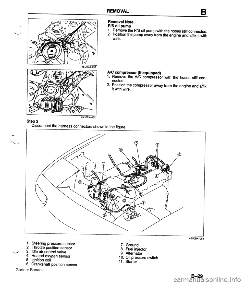
REMOVAL 6 Removal Note PIS oil pump 1. Remove the PIS oil pump with the hoses still connected. 2. Position the pump away from the engine and affix it with wire. 45UOBX-051 AIC compressor (If equipped) 1. Remove the NC compressor with the hoses still con- nected. 2. Position the compressor away from the engine and affix it with wire. I I 45UOBX-052 Step 2 Disconnect the harness connectors shown in the figure. 6 1. Steering pressure sensor 2. Throttle position sensor 3. Idle air control valve 4. Heated oxygen sensor 5. Ignition coil 6. Crankshaft position sensor 7. Ground 8. Fuel injector 9. Alternator 10. Oil pressure switch 11. Starter Gartner Banana
Page 73 of 1708

DISASSEMBLY AUXILIARY PARTS 1. Drain the engine oil. 2. Disassemble in the order shown in the figure. 1. Ignition coil and high-tension lead 2. Crankshaft position sensor 3. Manifold bracket 4. Intake manifold assembly 5. Alternator 6. Alternator bracket 7. Right engine mount 8. Oil filter 9. Oil cooler 10. Oil pressure switch 11. Water outlet pipe 12. Spark plug 13. Dipstick and pipe 14. Engine hanger Gartner Banana
Page 116 of 1708

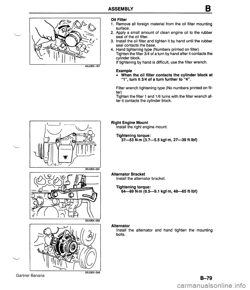
ASSEMBLY B Oil Filter 1. Remove all foreign material from the oil filter mounting surface. 2. Apply a small amount of clean engine oil to the rubber seal of the oil filter. 3. Install the oil filter and tighten it by hand until the rubber seal contacts the base. 4. Hand tightening type (Numbers printed on filter) Tighten the filter 314 of a turn by hand after it contacts the cylinder block. If tightening by hand is difficult, use the filter wrench. Example When the oil filter contacts the cylinder block at "l", turn it 314 of a turn further to "4". Filter wrench tightening type (No numbers printed on fil- ter) Tighten the filter 1 and 116 turns with the filter wrench af- ter it contacts the cylinder block. Right Engine Mount Install the right engine mount. Tightening torque: 37-53 N-m (3.7-5.5 kgf.m, 27-39 ft.lbf) Alternator Bracket Install the alternator bracket. Tightening torque: 64-49 N-m (6.5--9.1 kgf-m, 48-45 ft4bf) Alternator Install the alternator and hand tighten the mounting bolts. Gartner Banana