bolt pattern MAZDA MX-5 1994 Workshop Manual
[x] Cancel search | Manufacturer: MAZDA, Model Year: 1994, Model line: MX-5, Model: MAZDA MX-5 1994Pages: 1708, PDF Size: 82.34 MB
Page 351 of 1708
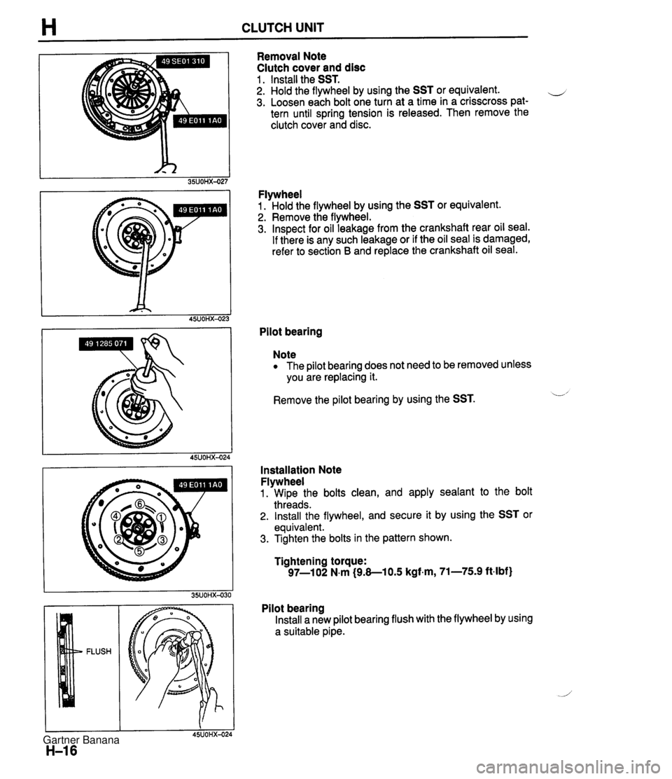
H CLUTCH UNIT Removal Note Clutch cover and disc 1 . Install the SST. 2. Hold the flywheel by using the SST or equivalent. e 3. Loosen each bolt one turn at a time in a crisscross pat- tern until spring tension is released. Then remove the clutch cover and disc. Flywheel 1. Hold the flywheel by using the SST or equivalent. 2. Remove the flywheel. 3. Inspect for oil leakage from the crankshaft rear oil seal. If there is any such leakage or if the oil seal is damaged, refer to section B and replace the crankshaft oil seal. Pilot bearing Note The pilot bearing does not need to be removed unless you are replacing it. Remove the pilot bearing by using the SST. L' Installation Note Flywheel 1. Wipe the bolts clean, and apply sealant to the bolt threads. 2. Install the flywheel, and secure it by using the SST or equivalent. 3. Tighten the bolts in the pattern shown. Tightening torque: 97-1 02 N.m (9.8-1 0.5 kgf.m, 71-75.9 ft-lbf) Pilot bearing Install a new pilot bearing flush with the flywheel by using a suitable pipe. Gartner Banana
Page 352 of 1708
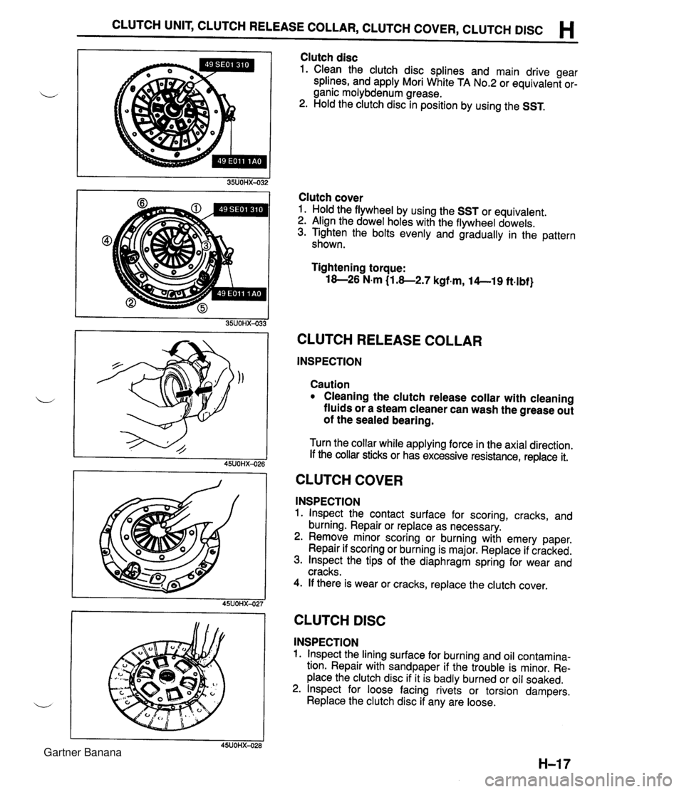
CLUTCH UNIT, CLUTCH RELEASE COLLAR, CLUTCH COVER, CLUTCH DlSC H Clutch disc 1. Clean the clutch disc splines and main drive gear splines, and apply Mori White TA No.2 or equivalent or- ganic molybdenum grease. 2. Hold the clutch disc in position by using the SST. Clutch cover 1. Hold the flywheel by using the SST or equivalent. 2. Align the dowel holes with the flywheel dowels. 3. Tighten the bolts evenly and gradually in the pattern shown. Tightening torque: 18-26 N.m (1.8-2.7 kgf.m, 14--19 ft.lbf} CLUTCH RELEASE COLLAR INSPECTION Caution Cleaning the clutch release collar with cleaning fluids or a steam cleaner can wash the grease out of the sealed bearing. Turn the collar while applying force in the axial direction. If the collar sticks or has excessive resistance, replace it. CLUTCH COVER INSPECTION 1. lnspect the contact surface for scoring, cracks, and burning. Repair or replace as necessary. 2. Remove minor scoring or burning with emery paper. Repair if scoring or burning is major. Replace if cracked. 3. lnspect the tips of the diaphragm spring for wear and cracks. 4. If there is wear or cracks, replace the clutch cover. I I 45UOHX-027 CLUTCH DlSC INSPECTION 1. lnspect the lining surface for burning and oil contamina- tion. Repair with sandpaper if the trouble is minor. Re- place the clutch disc if it is badly burned or oil soaked. 2. lnspect for loose facing rivets or torsion dampers. Replace the clutch disc if any are loose. Gartner Banana
Page 465 of 1708
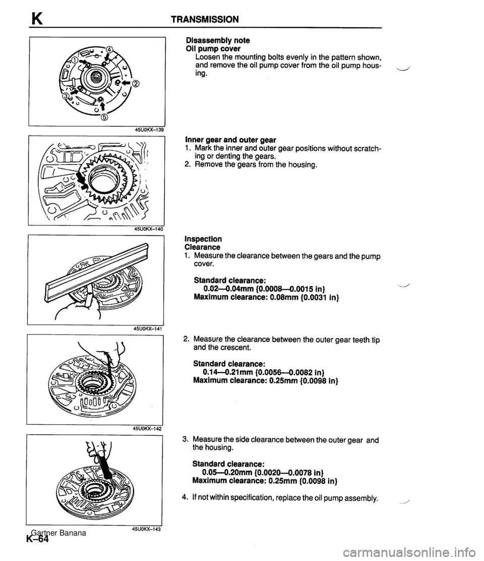
K TRANSMISSION Disassembly note Oil pump cover Loosen the mounting bolts evenly in the pattern shown, and remove the oil pump cover from the oil pump hous- ,-, ing . Inner gear and outer gear 1. Mark the inner and outer gear positions without scratch- ing or denting the gears. 2. Remove the gears from the housing. Inspection Clearance 1. Measure the clearance between the gears and the pump cover. Standard clearance: 0.02-0.04mm (0.0008-0.0015 in) Maximum clearance: 0.08mm (0.0031 in) 2. Measure the clearance between the outer gear teeth tip and the crescent. Standard clearance: 0.1 4-O.21 mm (0.0056-4.0082 in) Maximum clearance: 0.25mm (0.0098 in) 3. Measure the side clearance between the outer gear and the housing. Standard clearance: 0.05--0.20mm (0.0020--0.0078 in) Maximum clearance: 0.25mm (0.0098 in) 4. If not within specification, replace the oil pump assembly. -/' Gartner Banana
Page 543 of 1708
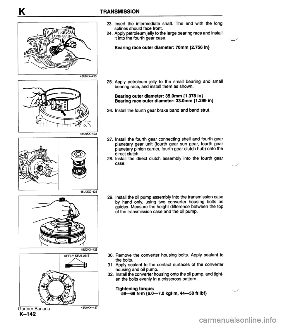
K TRANSMISSION APPLY SEALANT a 23. Insert the intermediate shaft. The end with the long splines should face front. 24. Apply petroleum jelly to the large bearing race and install it into the fourth gear case. 2 Bearing race outer diameter: 70mm (2.756 in) 25. Apply petroleum jelly to the small bearing and small bearing race, and install them as shown. Bearing outer diameter: 35.0mm (1.378 in) Bearing race outer diameter: 33.0mm (1.299 in) 26. lnstall the fourth gear brake band and band strut. 27. lnstall the fourth gear connecting shell and fourth gear planetary gear unit (fourth gear sun gear, fourth gear planetary pinion carrier, fourth gear clutch hub) onto the direct clutch. 28. lnstall the direct clutch assembly into the fourth gear case. --/ 29. lnstall the oil pump assembly into the transmission case by hand only, using two converter housing bolts as guides. Measure the height difference between the top of the transmission case and the oil pump. 30. Remove the converter housing bolts. Apply sealant to the bolts. 31. Apply sealant to the contact surfaces of the converter housing and oil pump. 32. lnstall the converter housing onto the oil pump, and tight- en the bolts evenly in a crisscross pattern. Tightening torque: 59-68 N-m (6.0-7.0 kgfm, 44--50 ft4bf) Gartner Banana
Page 550 of 1708
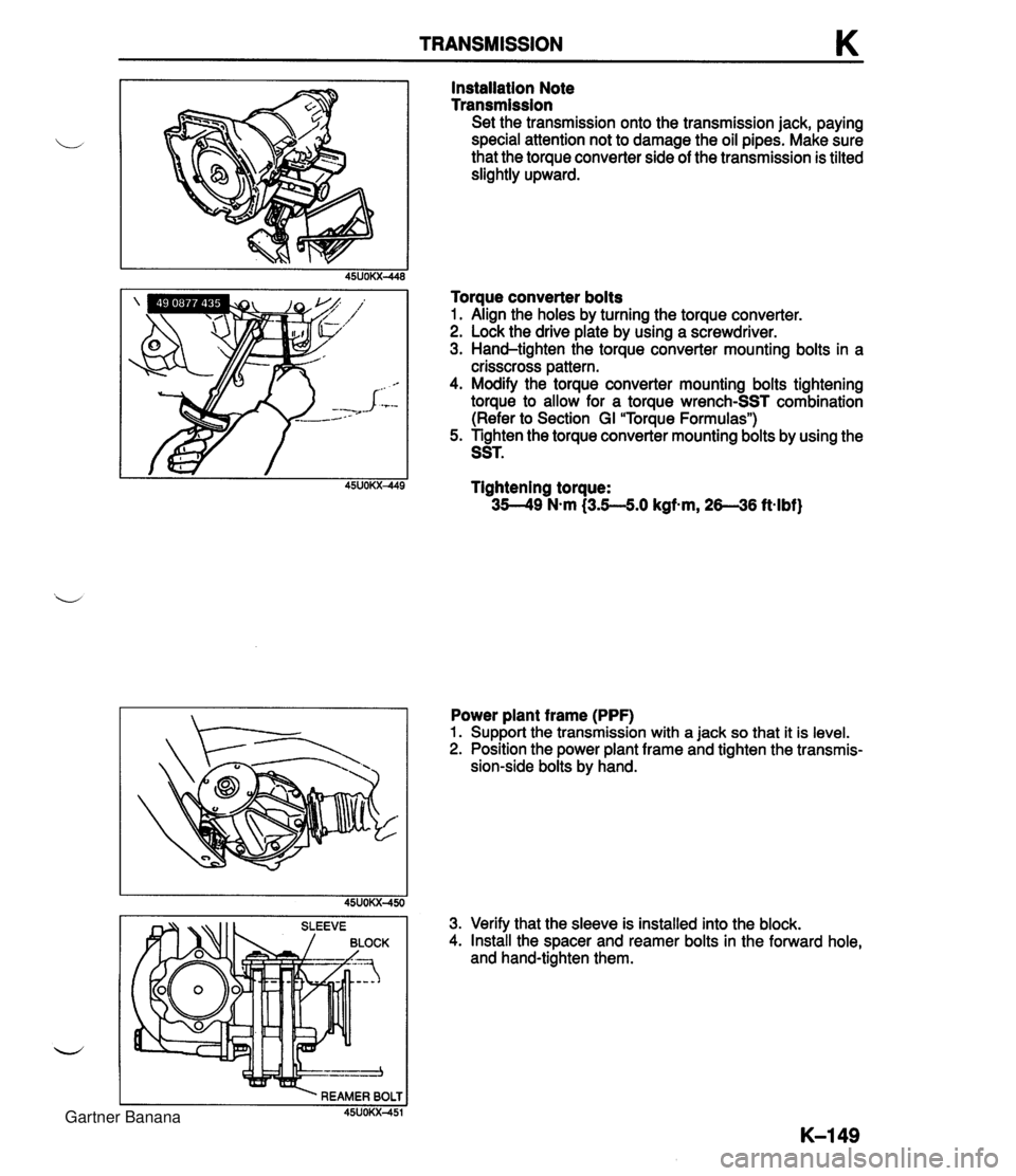
TRANSMISSION K Installation Note Transmission Set the transmission onto the transmission jack, paying special attention not to damage the oil pipes. Make sure that the torque converter side of the transmission is tilted slightly upward. Torque converter bolts 1. Align the holes by turning the torque converter. 2. Lock the drive plate by using a screwdriver. 3. Hand-tighten the torque converter mounting bolts in a crisscross pattern. 4. Modify the torque converter mounting bolts tightening torque to allow for a torque wrench-SST combination (Refer to Section GI "Torque Formulas") 5. Tighten the torque converter mounting bolts by using the SST. Tightening torque: 35-49 N-m (3.5-5.0 kgf-m, 26--36 ft-lbf) Power plant frame (PPF) 1. Support the transmission with a jack so that it is level. 2. Position the power plant frame and tighten the transmis- sion-side bolts by hand. 3. Verify that the sleeve is installed into the block. 4. Install the spacer and reamer bolts in the forward hole, and hand-tighten them. Gartner Banana
Page 731 of 1708
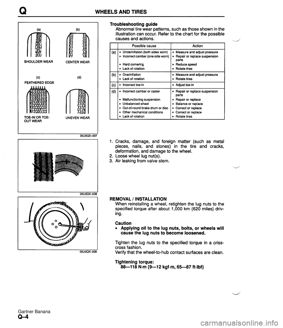
WHEELS AND TIRES SHOULDER WEAR CENTER WEAR (c) (4 FEATHERED EDGE TOE-IN OR TOE- UNEVEN WEAR OUT WEAR Troubleshooting guide Abnormal tire wear patterns, such as those shown in the illustration can occur. Refer to the chart for the possible causes and actions. d' Possible cause I Action I I Underinflation (both sides worn) I Measure and adjust pressure Overinflation Measure and adjust pressure Lack of rotation Rotate tires I Incorrect camber (one side worn) Hard cornering Lack of rotation Incorrect toe-in I Adjust toe-in I Repair or replace suspension parts Reduce speed Rotate tires 1. Cracks, damage, and foreign matter (such as metal pieces, nails, and stones) in the tire and cracks, deformation, and damage to the wheel. 2. Loose wheel lug nut(s). 3. Air leaking from valve stem. Incorrect camber or caster Malfunctioning suspension Unbalanced wheel Out-of-round brake drum or disc Other mechanical conditions Lack of rotation REMOVAL / INSTALLATION When reinstalling a wheel, retighten the lug nuts to the specified torque after about 1,000 km (620 miles} driv- ing. Repair or replace suspension parts Repair or replace Balance or replace Correct or replace Correct or replace Rotate tires Caution Applying oil to the lug nuts, bolts, or wheels will cause the lug nuts to become loosened. Tighten the lug nuts to the specified torque in a criss- cross fashion. Verify that the wheel-to-hub contact surfaces are clean. Tightening torque: 88-11 8 N.m (9-1 2 kgf.m, 65--87 ft-lbf) Gartner Banana