steering wheel MAZDA MX-5 1994 Workshop Manual
[x] Cancel search | Manufacturer: MAZDA, Model Year: 1994, Model line: MX-5, Model: MAZDA MX-5 1994Pages: 1708, PDF Size: 82.34 MB
Page 9 of 1708
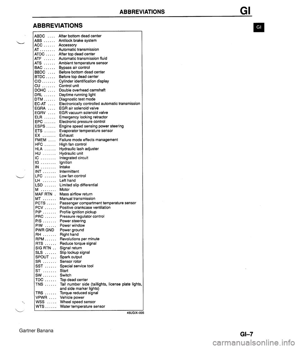
ABBREVIATIONS 4BDC .... 4BS ...... 4CC ...... 4T ........ 4TDC ..... 4TF ...... 4TS ...... 3AC ...... 3BDC .... 3TDC ..... :ID ....... 2U ....... IOHC .... IRL ...... ITM ...... IC-AT .... iGRA .... EGRV .... ELR ...... EPC ...... ESPS ..... ETS ...... EX ....... FMEM .... HFC ...... HLA ...... H U ....... IC ........ IG ........ IN ........ INT ....... LFC ...... LH ....... LSD ...... M ........ MAF RTN . MT ....... PCTS ..... PCV ...... PIP ....... PRC ...... PIS ....... PMI ...... PWR GND RH ....... RPM ...... RTS ...... SIG RTN . . SLS ...... ... SPOUT S R ....... SST ...... ST ....... SW ....... TDC ...... TNS ...... TRS ...... VPWR .... WSS ..... WTS...... After bottom dead center Antilock brake system Accessory Automatic transmission After top dead center Automatic transmission fluid Ambient temperature sensor Bypass air control Before bottom dead center Before top dead center Cylinder identification display Control unit Double overhead camshaft Daytime running light Diagnostic test mode Electronically controlled automatic transmission EGR air solenoid valve EGR vacuum solenoid valve Emergency locking retractor Electronic pressure control Engine speed sensing power steering Evaporator temperature sensor Exhaust Failure mode effects management High fan control Hydraulic lash adjuster Hydraulic unit Integrated circuit Ignition Intake Intermittent Low fan control Left hand Limited slip differential Motor Mass airflow return Manual transmission Passenger compartment temperature sensor Positive crankcase ventilation Profile ignition pickup Pressure regulator control Power steering Power window Power ground Right hand Revolutions per minute Reduce torque signal Signal return Slip lockup signal Spark output Sensor rotor Special service tool Start Switch Top dead center Tail number side (taillights, license plate lights and side marker lights) Torque reduced signal Vehicle power Wheel speed sensor Water temperature sensor Gartner Banana
Page 21 of 1708
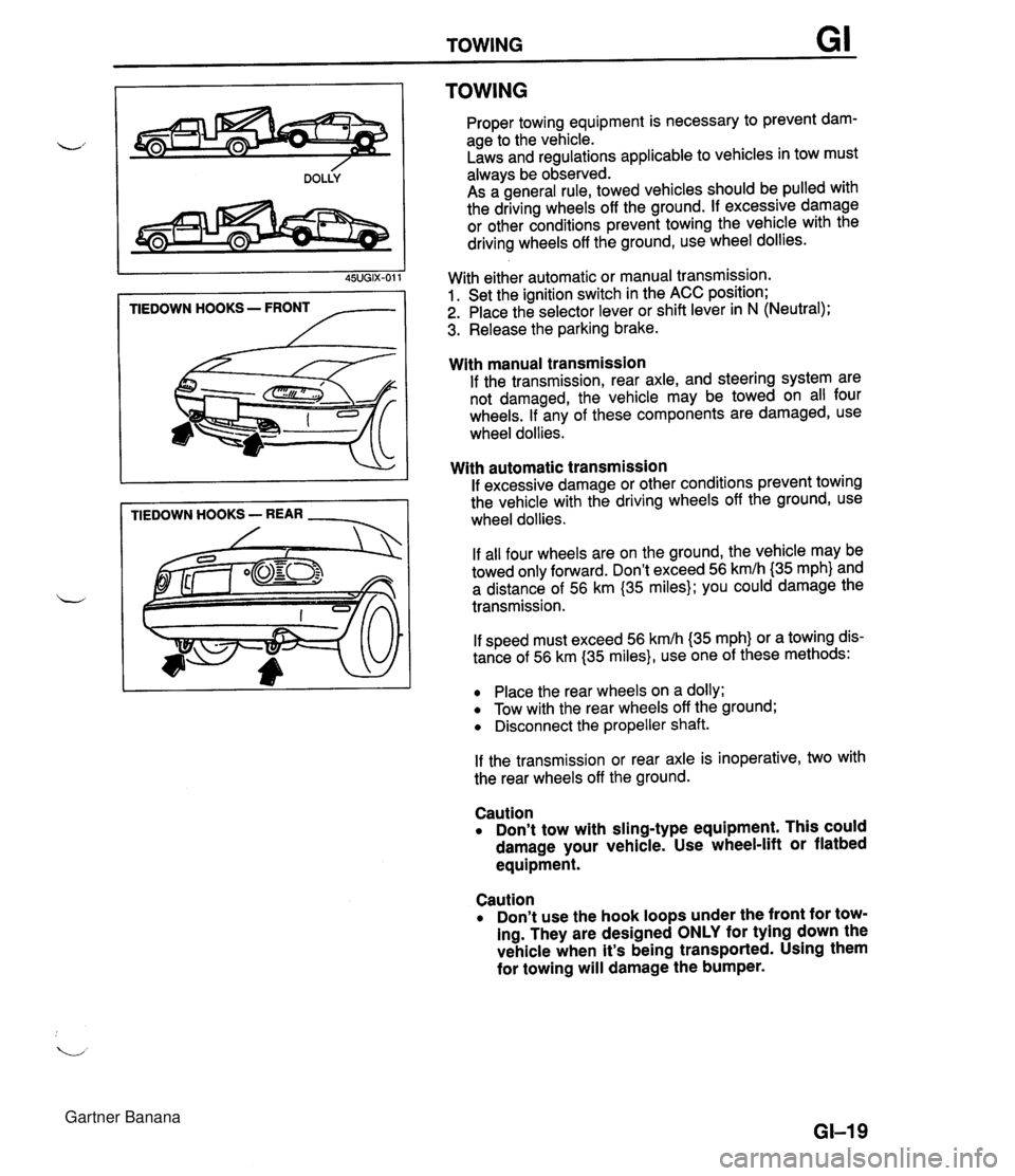
TOWING TIEDOWN HOOKS - FRONT /-- TIEDOWN HOOKS - REAR - TOWING Proper towing equipment is necessary to prevent dam- age to the vehicle. Laws and regulations applicable to vehicles in tow must always be observed. As a general rule, towed vehicles should be pulled with the driving wheels off the ground. If excessive damage or other conditions prevent towing the vehicle with the driving wheels off the ground, use wheel dollies. With either automatic or manual transmission. 1. Set the ignition switch in the ACC position; 2. Place the selector lever or shift lever in N (Neutral); 3. Release the parking brake. With manual transmission If the transmission, rear axle, and steering system are not damaged, the vehicle may be towed on all four wheels. If any of these components are damaged, use wheel dollies. With automatic transmission If excessive damage or other conditions prevent towing the vehicle with the driving wheels off the ground, use wheel dollies. If all four wheels are on the ground, the vehicle may be towed only forward. Don't exceed 56 kmlh {35 mph} and a distance of 56 km (35 miles); you could damage the transmission. If speed must exceed 56 kmlh (35 mph} or a towing dis- tance of 56 km (35 miles}, use one of these methods: Place the rear wheels on a dolly; Tow with the rear wheels off the ground; Disconnect the propeller shaft. If the transmission or rear axle is inoperative, two with the rear wheels off the ground. Caution Don't tow with sling-type equipment. This could damage your vehicle. Use wheel-lift or flatbed equipment. Caution Don't use the hook loops under the front for tow- ing. They are designed ONLY for tying down the vehicle when it's being transported. Using them for towing will damage the bumper. GI-I 9 Gartner Banana
Page 23 of 1708
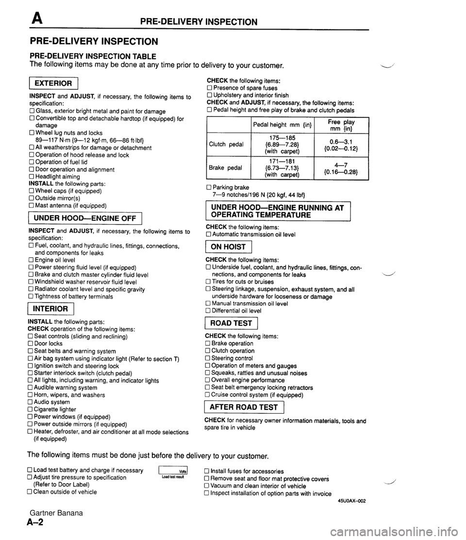
PRE-DELIVERY INSPECTION PRE-DELIVERY INSPECTION PRE-DELIVERY INSPECTION TABLE The following items may be done at any time prior to delivery to your customer. INSPECT and ADJUST, if necessary, the following items to specification: 0 Glass, exterior bright metal and paint for damage 0 Convertible top and detachable hardtop (if equipped) for damage 0 Wheel lug nuts and locks 89-117 N.m (9-1 2 kgf.m, 66-86 ft4bf) 0 All weatherstrips for damage or detachment Operation of hood release and lock Operation of fuel lid 0 Door operation and alignment Headlight aiming INSTALL the following parts: Wheel caps (if equipped) 0 Outside mirror(s) 0 Mast antenna (if equipped) UNDER HOOD-ENGINE OFF INSPECT and ADJUST, if necessary, the following items to specification : Fuel, coolant, and hydraulic lines, fittings, connections, and components for leaks Engine oil level 0 Power steering fluid level (if equipped) Brake and clutch master cylinder fluid level 0 Windshield washer reservoir fluid level 0 Radiator coolant level and specific gravity 0 Tightness of battery terminals pKiq INSTALL the following parts: CHECK operation of the following items: 0 Seat controls (sliding and reclining) 0 Door locks 0 Seat belts and warning system 0 Air bag system using indicator light (Refer to section T) Ignition switch and steering lock 0 Starter interlock switch (clutch pedal) All lights, including warning, and indicator lights 0 Audible warning system 0 Horn, wipers, and washers Audio system 0 Cigarette lighter Power windows (if equipped) 0 Power outside mirrors (if equipped) 0 Heater, defroster, and air conditioner at all mode selections (if equipped) CHECK the following items: Presence of spare fuses 0 Upholstery and interior finish CHECK and ADJUST, if necessary, the following items: 0 Pedal height and free play of brake and clutch pedals I Pedal height mm {in} I Ft: $iy I Clutch pedal {6.89--7.28) (with carpet) Parking brake 7-9 notchesil96 N (20 kgf, 44 Ibf) 0.63.1 (0.024. 12) Brake pedal RUNNING AT OPERATING TEMPERATURE CHECK the following items: 0 Automatic transmission oil level 171-181 (6.73--7.13) (with carpet) I ON HOIST I 4--7 {0.16-0.28} CHECK the following items: 0 Underside fuel, coolant, and hydraulic lines, fittings, con- nections, and components for leaks 4 Tires for cuts or bruises 0 Steering linkage, suspension, exhaust system, and all underside hardware for looseness or damage Manual transmission oil level Differential oil level I ROAD TEST I CHECK the following items: Brake operation Clutch operation 0 Steering control 0 Operation of meters and gauges Squeaks, rattles and unusual noises 0 Overall engine performance Seat belt emergency locking retractors 0 Cruise control system (if equipped) I AFTER ROAD TEST I CHECK for necessary owner information materials, tools and spare tire in vehicle The following items must be done just before the delivery to your customer. 0 Load test battery and charge if necessary -1 Install fuses for accessories Adjust tire pressure to specification Load test fesuk 0 Remove seat and floor mat protective covers (Refer to Door Label) 0 Vacuum and clean interior of vehicle Clean outside of vehicle Inspect installation of option parts with invoice 45UOAX-002 Gartner Banana
Page 159 of 1708
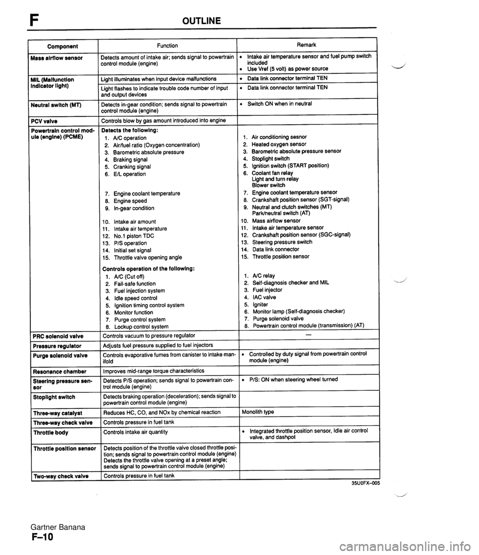
Neutral swltch (MT) 7 PCV valve Powertrain control mod- ule (engine) (PCME) Purge solenoid valve Resonance chamber Steering pressure sen- Stoplight swltch I Throttle posltion sensor r [Two-way check valve Function jetects amount of intake air; sends signal to powertrain :ontrol module (engine) Li~ht illuminates when input device malfunctions - Light flashes to indicate trouble code number of input and output devices Detects in-gear condition; sends signal to powertrain :ontrol module (engine) - Controls blow by aas amount introduced into engine Detects the followlng: 1. A/C operation 2. Airlfuel ratio (Oxygen concentration) 3. Barometric absolute pressure 4. Braking signal 5. Cranking signal 6. EIL operation 7. Engine coolant temperature 8. Engine speed 9. In-gear condition 10. lntake air amount 11, lntake air temperature 12. No.1 piston TDC 13. PIS operation 14. Initial set signal 15. Throttle valve opening angle Controls operatlon of the followlng: 1. AIC (Cut off) 2. Fail-safe function 3. Fuel injection system 4. ldle speed control 5. Ignition timing control system 6. Monitor function 7. Purge control system 8. Lockup control svstem Controls vacuum to pressure regulator -- Adjusts fuel pressure supplied to fuel injectors Controls evaporative fumes from canister to intake man- ifold -- lm~roves mid-ranae torque characteristics -. Detects PIS operation; sends signal to powertrain con- trol module (engine) -- Detects braking operation (deceleration); sends signal to powertrain control module (engine) Reduces HC, CO, and NOx by chemical reaction Controls pressurein fuel tank Controls intake air quantity Detects position of the throttle valve closed throttle posi- tion; sends signal to powertrain control module (engine) Detects the throttle valve opening at a preset angle; sends si~nal to powertrain control module (engine) controls pressure in fuel tank Remark lntake air temperature sensor and fuel pump switch included Use Vref (5 volt) as power source ' Data link connector terminal TEN ' Data link connector terminal TEN Switch ON when in neutral 1, Air conditioning sesnor 2. Heated oxygen sensor 3. Barometric absolute pressure sensor 4. Stoplight switch 5. Ignition switch (START position) 6. Coolant fan relay Light and turn relay Blower switch 7. Engine coolant temperature sensor 8. Crankshaft position sensor (SGT-signal) 9. Neutral and dutch switches (MT) Parklneutral switch (AT) 10. Mass airflow sensor 11, lntake air temperature sensor 12. Crankshaft position sensor (SGC-signal) 13. Steering pressure switch 14. Data link connector 15. Throttle position sensor 1. NC relay 2. Self-diagnosis checker and MIL 3. Fuel injector 4. IAC valve 5. Igniter 6. Monitor lamp (Self-diagnosis checker) 7. Purge solenoid valve 8. Powertrain control module (transmission) (AT) D Controlled by duty signal from powertrain control module (engine) D PIS: ON when steering wheel turned Monolith type D Integrated throttle position sensor, Idle air control valve, and dashpol Gartner Banana
Page 307 of 1708

CONTROL SYSTEM Replacement Replace the neutral switch as shown in the figure. STEERING PRESSURE SENSOR Inspection 1. Disconnect the steering pressure sensor connector. 2. Connect an ohmmeter to the switch. 3. Start the engine and let it idle. Check continuity of the switch while turning the steering wheel. PIS 1 Continuity Turnina Yes " I t ~ot turning I NO 4. If not as specified, replace the steering pressure sensor. Replacement Replace the steering pressure sensor as shown in the figure. Gartner Banana
Page 586 of 1708
Before beginning any service procedure. refer to section T of this manual for air bag system service warnings and audio antitheft system alarm conditions . FRONT AND REAR AXLES ....................................... INDEX M- 2 ..................................... OUTLINE M- 3 SPECIFICATIONS ........................... M- 3 TROUBLESHOOTING GUIDE .................. M- 4 ............................... FRONT AXLE M- 4 ................................ REAR AXLE M- 4 ............................. DIFFERENTIAL M- 4 ................................. FRONT AXLE M- 5 PREPARATION ............................. M- 5 WHEEL HUB. STEERING KNUCKLE .......... M- 6 .................................. REAR AXLE M-10 PREPARATION ............................. M-10 ......................... DISC BRAKE TYPE M-11 ................................ DRIVE SHAFT M-17 .................... DOUBLE OFFSET JOINT M-17 ............................... DIFFERENTIAL M-23 PREPARATION ............................. M-23 DIFFERENTIAL OIL ......................... M-25 ................. OIL SEAL (OUTPUT SHAFT) M-25 DIFFERENTIAL. STANDARD; DIFFERENTIAL. TORQUE SENSING LIMITED SLIP ("TORSEN" LSD) ........................... M-27 45UOMX-001 "TORSEN" is a registered trademark of ZEXEL-GLEASON USA . INC Gartner Banana
Page 589 of 1708

TROUBLESHOOTING GUIDE TROUBLESHOOTING GUIDE FRONT AXLE I Problem Posslbk Cause Worn or damaged wheel bearing Worn or damaged wheel bearing Steering wheel vibration braking Action Replace Replace REAR AXLE Page M- 6 M-6 I Problem Possible Cause Bent drive shaft Page Action Replace I Abnormal nolse Worn or damaged wheel bearing Worn drive shaft spline Worn or deteriorated upper arm bushing M-13 Replace I M-17 Body "rolls" I Replace section R Body leans Weak upper arm bushing Abnormal nolse from suspension system Worn or deteriorated upper arm bushing DIFFERENTIAL Problem Posrlble Cause lnsufficient differential oil Incorrect differential oil lmproperly adjusted ring gear backlash Poor contact of ring gear teeth Worn or damaged side bearing Worn or damaged ring gear Worn or damaged drive pinion bearing Worn or damaged pinion and side gear (STANDARD) Worn or damaged gear in LSD assembly ("TORSEN" LSD) Seized side gear and case Worn side gear spline Worn pinion shaft Worn thrust washer Worn or damaged needle bearing ("TORSEN" LSD) lmproperly adjusted side gear backlash lmproperly adjusted drive pinion gear preload Action Add oil Replace Adjust Adjust Replace Replace Replace Replace Replace Page M-25 M-25 M40 M4l M-32 M-32 M-32 M-32 M-32 M-32 M-32 M-32 M-32 M-32 M-40 M-39 Abnormal nolse Replace Replace Replace Replace Replace Adjust Adjust Heat buildup lnsufficient differential oil lnsufficient drive pinion gear backlash Excessive bearing preload Add oil Adjust Adjust Oil leakage Excessive differential oil Loose differential carrier Worn or damaged oil seal Remove oil Tighten or repair Replace I - No dlfferentlal operation I Misassembled or damaged Repair Gartner Banana
Page 591 of 1708
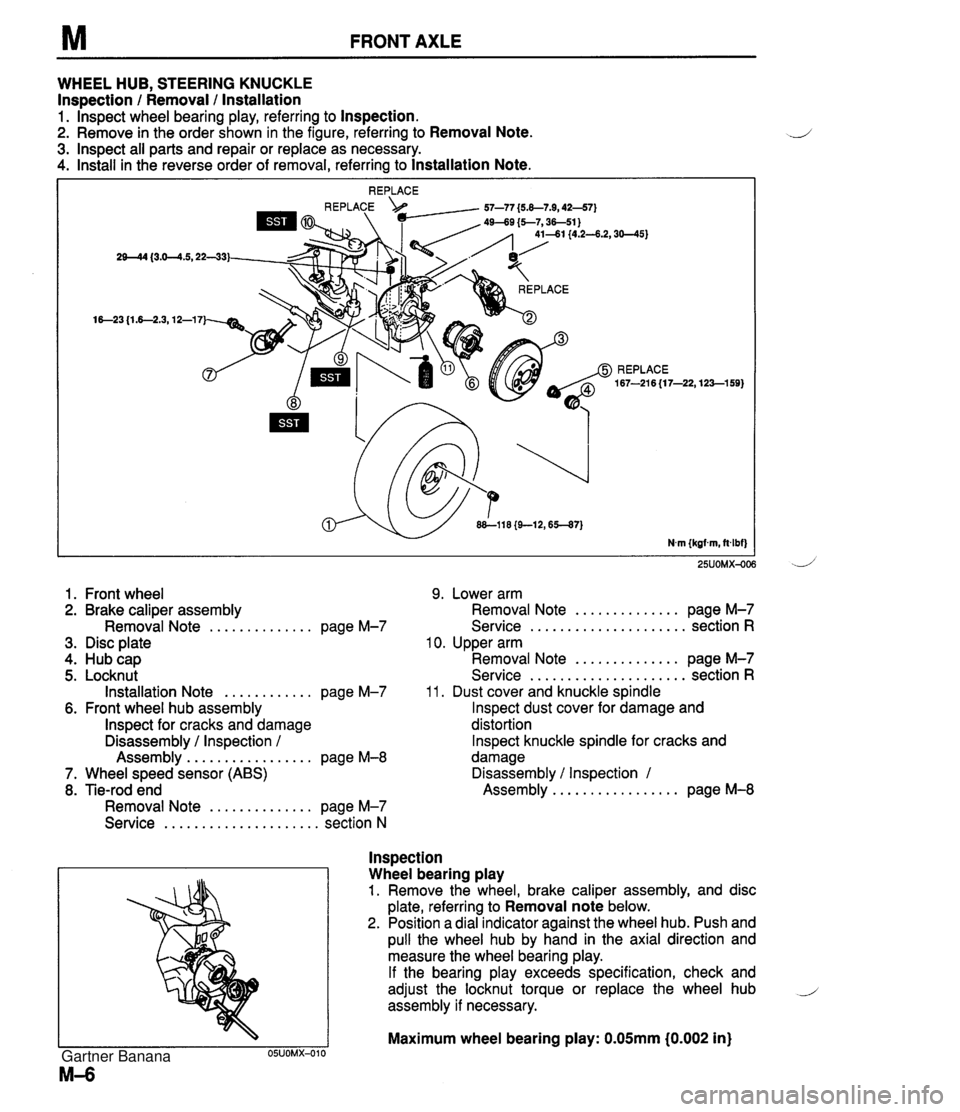
FRONT AXLE WHEEL HUB, STEERING KNUCKLE Inspection / Removal / lnstallation 1. lnspect wheel bearing play, referring to Inspection. 2. Remove in the order shown in the figure, referring to Removal Note. 3. lnspect all parts and repair or replace as necessary. 4. Install in the reverse order of removal, referring to Installation Note. 25UOMX-OC 1. Front wheel 9. Lower arm 2. Brake caliper assembly Removal Note .............. page M-7 3. Disc plate 4. Hub cap 5. Locknut Installation Note ............ page M-7 6. Front wheel hub assembly lnspect for cracks and damage Disassembly / Inspection / Assembly ................. page M-8 7. Wheel speed sensor (ABS) 8. Tie-rod end Removal Note .............. page M-7 Service ..................... section N .............. Removal Note page M-7 ..................... Service section R 10. Upper arm .............. Removal Note page M-7 ..................... Service section R 11. Dust cover and knuckle spindle lnspect dust cover for damage and distortion lnspect knuckle spindle for cracks and damage Disassembly / Inspection 1 ................. Assembly page M-8 lnspection Wheel bearing play 1. Remove the wheel, brake caliper assembly, and disc plate, referring to Removal note below. 2. Position a dial indicator against the wheel hub. Push and pull the wheel hub by hand in the axial direction and measure the wheel bearing play. If the bearing play exceeds specification, check and adjust the locknut torque or replace the wheel hub i assembly if necessary. Maximum wheel bearing play: 0.05mm i0.002 in) Gartner Banana
Page 628 of 1708

Before beginning any service procedure. refer to section T of this manual for I air bag system service warnings and audio antitheft system alarm conditions . STEERING SYSTEM INDEX ....................................... N- 2 OUTLINE ..................................... N- 4 SPECIFICATIONS ........................... N- 4 MANUAL STEERING .......................... N- 4 PREPARATION ............................. N- 4 ................ TROUBLESHOOTING GUIDE N- 5 BOOT ...................................... N- 6 STEERING WHEEL AND COLUMN ........... N- 8 ............. STEERING GEAR AND LINKAGE N-12 ENGINE SPEED SENSING POWER STEERING .......................... N-18 PREPARATION ............................. N-18 TROUBLESHOOTING GUIDE ................ N-20 AIR BLEEDING ............................. N-21 POWER STEERING FLUID ................... N-22 STEERING WHEEL AND COLUMN ........... N-24 STEERING GEAR AND LINKAGE ............. N-25 POWER STEERING OIL PUMP ............... N-33 DRIVE BELT ................................ N-37 25UONX-001 Gartner Banana
Page 629 of 1708
![MAZDA MX-5 1994 Workshop Manual INDEX INDEX MANUAL STEERING STEERING WHEEL PLAY: [ (MOrnrn (0-1 .I 8 in) ] 1. Boot 3. Steering gear and linkage Replacement ................ page N- 6 Removal 1 Installation ......... page N-12 2. Ste MAZDA MX-5 1994 Workshop Manual INDEX INDEX MANUAL STEERING STEERING WHEEL PLAY: [ (MOrnrn (0-1 .I 8 in) ] 1. Boot 3. Steering gear and linkage Replacement ................ page N- 6 Removal 1 Installation ......... page N-12 2. Ste](/img/28/57072/w960_57072-628.png)
INDEX INDEX MANUAL STEERING STEERING WHEEL PLAY: [ (MOrnrn (0-1 .I 8 in) ] 1. Boot 3. Steering gear and linkage Replacement ................ page N- 6 Removal 1 Installation ......... page N-12 2. Steering wheel and column Disassembly / Inspection / On-vehicle inspection ......... page N- 8 Assembly .................. page N-13 -, Removal / Installation ......... page N- 9 Disassembly / Inspection / Assembly .................. page N-10 Gartner Banana