gas type MAZDA MX-5 1994 Workshop Manual
[x] Cancel search | Manufacturer: MAZDA, Model Year: 1994, Model line: MX-5, Model: MAZDA MX-5 1994Pages: 1708, PDF Size: 82.34 MB
Page 5 of 1708

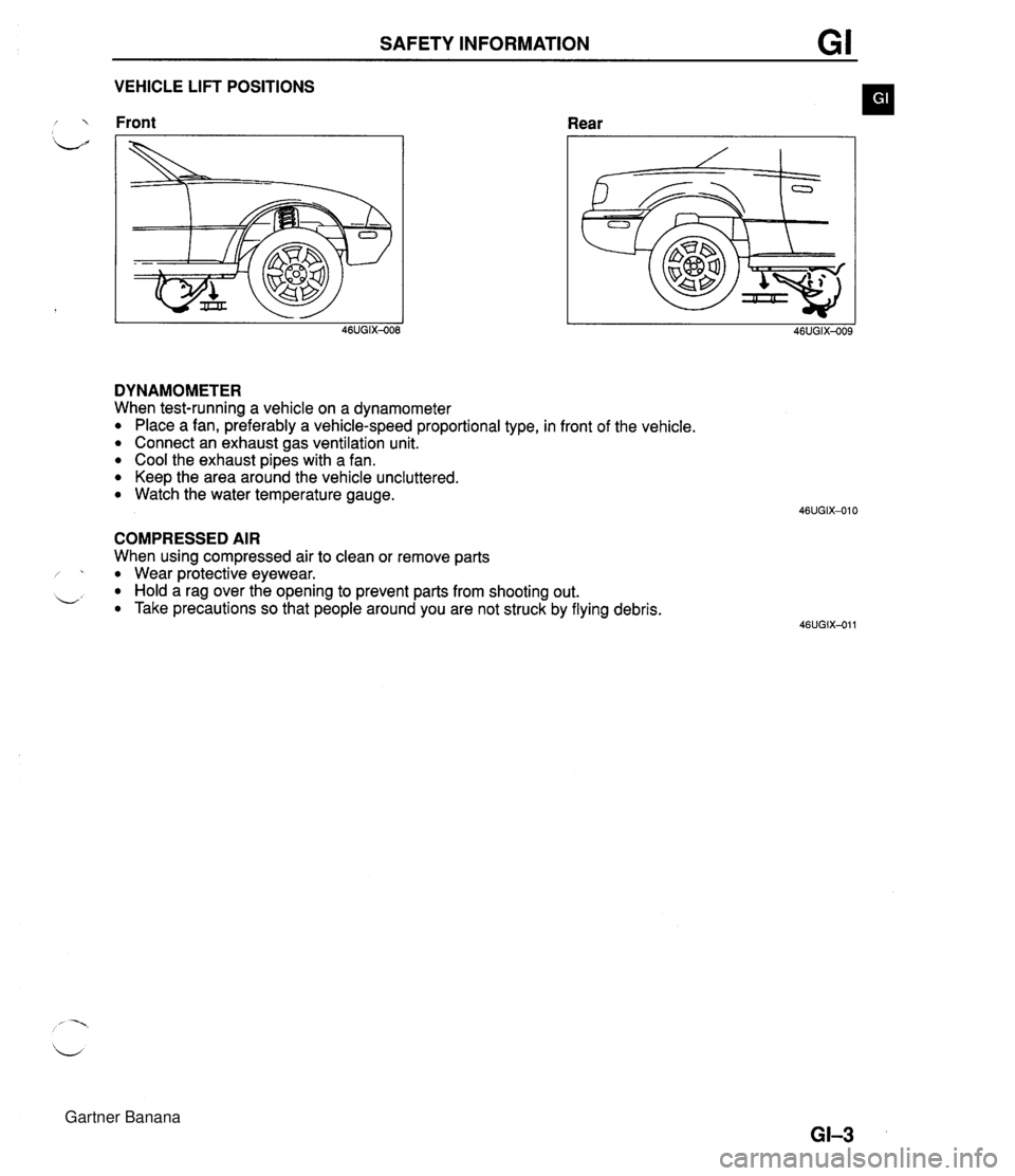
SAFETY INFORMATION VEHICLE LIFT POSITIONS Front DYNAMOMETER Rear When test-running a vehicle on a dynamometer Place a fan, preferably a vehicle-speed proportional type, in front of the vehicle. Connect an exhaust gas ventilation unit. Cool the exhaust pipes with a fan. Keep the area around the vehicle uncluttered. Watch the water temperature gauge. COMPRESSED AIR When using compressed air to clean or remove parts / Wear protective eyewear. L- a Hold a rag over the opening to prevent parts from shooting out. Take precautions so that people around you are not struck by flying debris. Gartner Banana
Page 128 of 1708

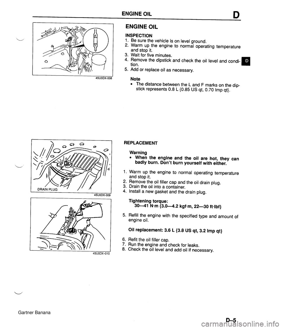
ENGINE OIL D ENGINE OIL INSPECTION 1. Be sure the vehicle is on level ground. 2. Warm up the engine to normal operating temperature and stop it. 3. Wait for five minutes. 4. Remove the dipstick and check the oil level and condi- tion. 5. Add or replace oil as necessary. Note The distance between the L and F marks on the dip- stick represents 0.8 L (0.85 US qt, 0.70 Imp qt}. REPLACEMENT Warning When the engine and the oil are hot, they can badly burn. Don't burn yourself with either. 1. Warm up the engine to normal operating temperature and stop it. 2. Remove the oil filler cap and the oil drain plug. 3. Drain the oil into a container. 4. Install a new gasket and the drain plug. Tightening torque: 3041 N-m 13.0-4.2 kgf.m, 22-30 ft-lbf) 5. Refill the engine with the specified type and amount of engine oil. Oil replacement: 3.6 L 13.8 US qt, 3.2 Imp qt) 6. Refit the oil filler cap. 7. Run the engine and check for leaks. 8. Check the oil level and add oil if necessary. Gartner Banana
Page 133 of 1708

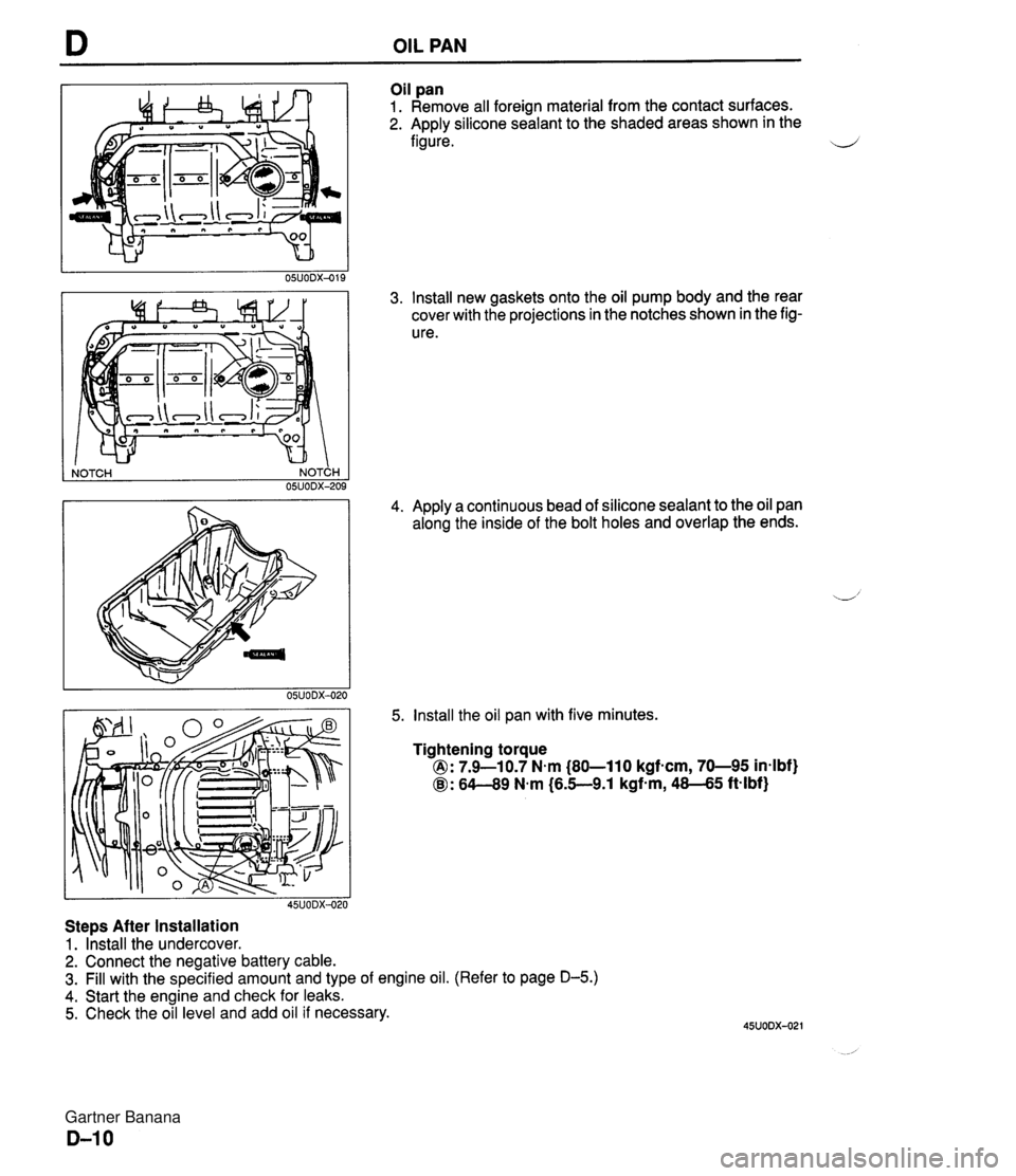
OIL PAN NOTCH NOTCH I 05UODX-209 Steps After Installation 1. Install the undercover. Oil pan 1. Remove all foreign material from the contact surfaces. 2. Apply silicone sealant to the shaded areas shown in the figure. 3. Install new gaskets onto the oil pump body and the rear cover with the projections in the notches shown in the fig- ure. 4. Apply a continuous bead of silicone sealant to the oil pan along the inside of the bolt holes and overlap the ends. 5. Install the oil pan with five minutes. Tightening torque 0: 7.9-10.7 N.m (80-110 kgf-cm, 70-95 in4bf) @: 64-49 N.m (6.5-9.1 kgf-m, 48-45 ft-lbf) 2. Connect the negative battery cable. 3. Fill with the specified amount and type of engine oil. (Refer to page D-5.) 4. Start the engine and check for leaks. 5. Check the oil level and add oil if necessary. Gartner Banana
Page 158 of 1708

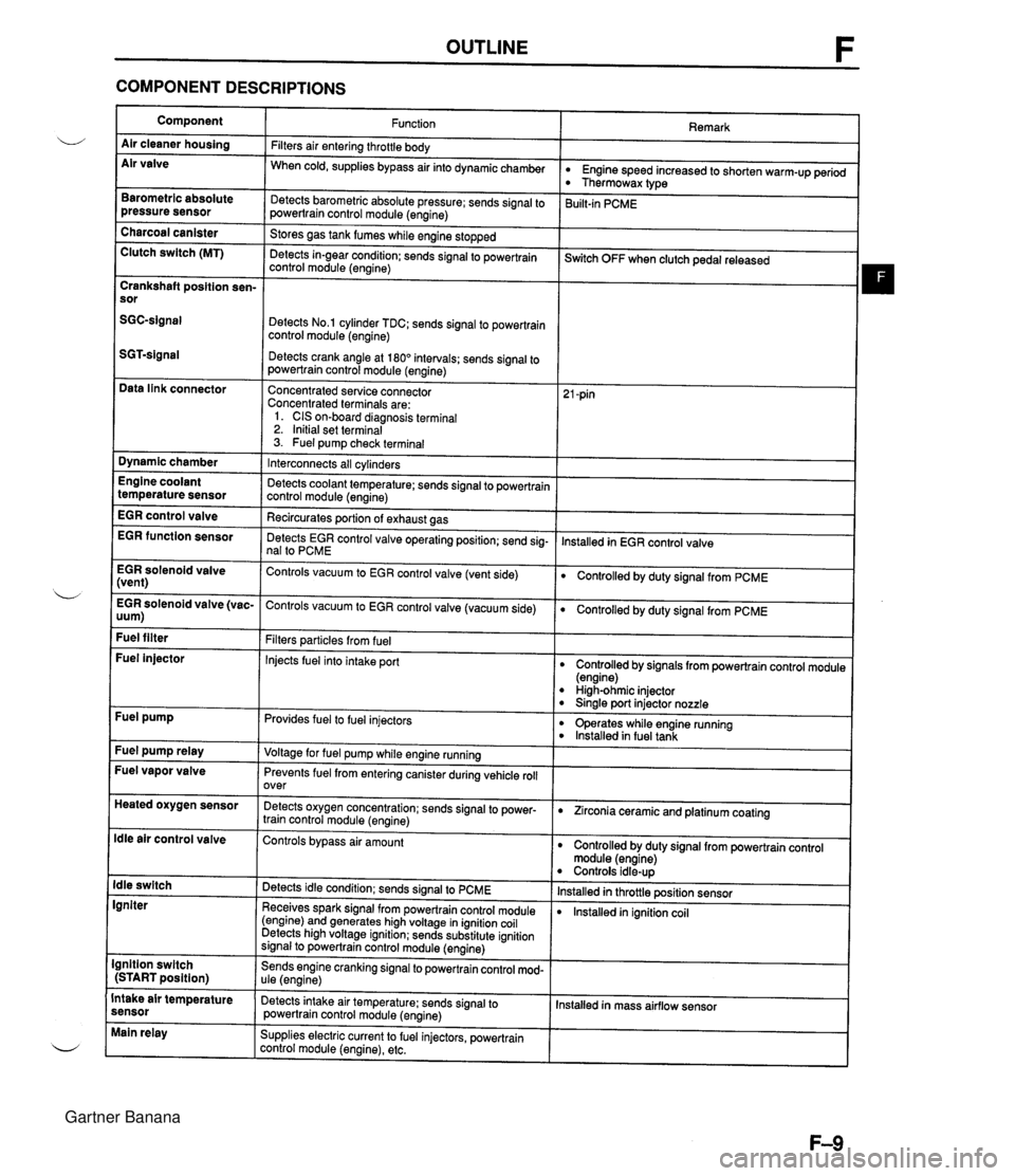
OUTLINE F COMPONENT DESCRIPTIONS Component Air cleaner housing Air valve Remark Function Filters air entering throttle body When cold, supplies bypass air into dynamicchamber w Engine speed increased to shorten warm-up period Thermowax type Barometric absolute pressure sensor Detects barometric absolute pressure; sends signal to powertrain control module (engine) 3uilt-in PCME Charcoal canister Clutch switch (MT) Stores gas tank fumes while engine stopped Detects in-gear condition: sends signal to powertrain control module (engine) --- ~witch OFF when clutch pedal released Crankshaft position sen- sor Detects No.1 cylinder TDC; sends signal to powertrain control module (engine) Detects crank angle at 180" intervals; sends signal to powertrain control module (engine) Data link connector Concentrated service connector Concentrated terminals are: 1. CIS on-board diagnosis terminal 2. Initial set terminal 3. Fuel pump check terminal Dynamic chamber Interconnects all cylinders Detects coolant temperature; sends signal to powertrain control module (engine) Recircurates oortion of exhaust aas Engine coolant temperature sensor EGR control valve lnstalled in EGR control valve EGR function sensor Detects EGR control valve operating position; send sig- nal to PCME EGR solenoid valve (vent) Controls vacuum to EGR control valve (vent side) Controlled by duty signal from PCME . - EGR solenoid valve (vac- Controls vacuum to EGR control valve (vacuum side) 0 Controlled by duty signal from PCME uum) Fuel filter Filters particles from fuel Injects fuel into intake port Fuel injector Controlled by signals from powertrain control module (engine) High-ohmic injector 0 Sinale port injector nozzle Fuel pump Provides fuel to fuel injectors 0 operates while engine running lnstalled in fuel tank Fuel pump relay Voltage for fuel pump while engine running Fuel vapor valve Prevents fuel from entering canister during vehicle roll over Heated oxygen sensor Detects oxygen concentration; sends signal to power- train control module (engine) 0 Zirconia ceramic and platinum coating ldle air control valve Controls bypass air amount Controlled by duty signal from powertrain control module (engine) Controls idle-up lnstalled in throttle position sensor lnstalled in ignition coil ldle switch Igniter Detects idle condition; sends signal to PCME Receives spark signal from powertrain control module (engine) and generates high voltage in ignition coil Detects high voltage ignition; sends substitute ignition signal to powertrain control module (engine) Ignition switch (START position) Sends engine cranking signal to powertrain control mod- ule (engine) Intake air temperature sensor Detects intake air temperature: sends signal to powertrain control module (engine) Installed in mass airflow sensor Main relay Supplies electric current to fuel injectors, powertrain control module (engine), etc. Gartner Banana
Page 736 of 1708

OUTLINE OUTLINE SPECIFICATIONS Front Suspension - Transmission item (Stabilizer Specifications MT I AT - I Susoension tvoe I . , . , I . , Shock absorber Cylindrical double acting, low-pressure-gas charged I Double-wishbone TY pe Torsion bar Coil spring I - Diameter mm linl I 20.0 10.79) Identification mark color 19.0 (0.75) White Wire diameter mm (in) Coil inner diameter mm {in) I Blue Free length mm {in) Coil number 11 .O (0.43) 83 i3.27) 11 .O (0.43) 83 (3.27) 292.5 (1 1 32) 6.32 3 +. 3 (0.12 + 0.12) 0°18' + 18' Total toe-in I - I 35UORX-001 Rear Suspension 302.0 (1 1.89) 6.32 mm {in) degree Total toe-in (per side) 1 degree Front wheel alignment (Unladedt1) 0°09' +. 09' Caster anglee3 4"26' +. 45' Kingpin angle 11 "20' Maximum steering angle Transmission Specifications MT I AT Item Differential - Suspension type Inner Outer "TORSEN" LSD 1 Standard Double-wishbone Coil springs 370 23' a 2" 32" 32' -t 2" Camber anglee2 Torsion bar 12.0 (0.47) 1 11.0 (0.43) 1 11 .O (0.43) Cylindrical double acting, low-pressure-gas charged - Stabilizer Identification mark color Wire diameter mm {in) 0°24' + 45' Type Diameter mm {in) I Coil number I 7.68 I 7.96 I Shock absorber Yellow 10.1 {0.40} Coil inner diameter mm {in) Free length mm {in) Green 10.2 {0.40) 35UORX-002 *I Fuel tank full; radiator coolant and engine oil at specified levels; spare tire, jack, and tools in designated positions. '2 Difference between left and right must not exceed I O. '3 Difference between left and right must not exceed 1'30'. "TORSEN" is a registered trademark of ZEXEL-GLEASON USA.INC 83 I3.27) 348.5 j13.72) Rear wheel alignment (Unladed*') 83 (3.27) 356.5 (1 4.04) Total toe-in Total toe-in (per side) mm (in) degree degree 3 -c 3 (0.12 + 0.121 0°18' + 18' 0°09' + 09' Camber angle*2 -0°43' 2 30' Gartner Banana
Page 1122 of 1708

TECHNICAL DATA R. SUSPENSION Front sus~ension I i/ Differential - . - ~- Coil springs MT I AT Shock absorbers "TORSEN" LSD TY ~a Cylindrical double-acting, low-pressure gas charged Standard Stabilizer Double-wishbone Torsion bar Wire diameter mm {in) Coil inner diameter mm {in} Rear suspension Tv~e I Double-wishbone TY pe Diameter mm {in) 20.0 (0.79) I Identification color 11 .O {0.43} 83.0 f3.27) . . Free length mm {in) Coil number 19.0 {0.75} . . 292.5 (1 1.52) 1 302.0 {I 1.89) 6.32 I - . I1 . ,I . , I Shock absorbers Cylindrical double-acting, low-pressure gas charged White I I Identification color I Yellow I Green I Blue Torsion bar 12.0 (0.471 1 11 .O 10.43) .a Stabilizer TYPe Diameter mm {in) Coil springs Wheel alignment I Front wheel alignment (Unladen'') I I - Caster angle*3 King pin angle I tun'aoen 'I 1 Camber angle'2 -0°43' 2 30' I I - Wire diameter mm {in) Coil inner diameter mm {in) Free length mm {in} Coil number Maximum steering angle 4O26' -c 45' 11 "20' Rear wheel alignment ,, l-l_A_-*i, *1 Fuel tank full; radiator coolant and engine oil at specified level, and spare tire, jack, and tools in designated position. *2 Difference between left and right must not exceed lo. *3 Difference between left and right must not exceed 1'30'. 10.1 (0.40) Inner Outer 10.2 I0.40) mm (in) Camber ana~e*~ J 3 + 3 10.12 r 0.12) 0°18' 2 18' -. - 3 r 3 {0.12 2 0.12) 0'24' 2 45' 37O23' 2 2" 32O32' 2 2" Total toe-in 83.0 i3.27) U' mm {in} degree 348.5 113.72) Total toe-in 356.5 {I 4.04) dearee 7.68 0'18' & 18' 7.96 Gartner Banana