wheel bolts MAZDA MX-5 1994 Workshop Manual
[x] Cancel search | Manufacturer: MAZDA, Model Year: 1994, Model line: MX-5, Model: MAZDA MX-5 1994Pages: 1708, PDF Size: 82.34 MB
Page 80 of 1708

DISASSEMBLY B PROTECT PUMP BODY WlTH RAG 05UOBX-10; I PROTECT REAR COYER WITH RAG I Disassembly Note Flywheel (MT) or drive plate (AT) 1. Hold the flywheel with the SST. 2. Remove the flywheel lock bolts. 3. Remove the flywheel. Oil pan 1. Remove the oil pan mounting bolts. Caution Pry tools can easily scratch the cylinder block and oil pan contact surfaces. 2. Insert a screwdriver only at the points shown in the fig- ure. 3. Remove the oil pan. Oil pan baffle 1. Insert a screwdriver between the cylinder block and the baffle to separate them. 2. Remove the baffle. Front oil seal Remove the oil seal with a screwdriver protected with a rag. Rear oil seal Remove the oil seal with a screwdriver protected with a rag. Gartner Banana
Page 105 of 1708

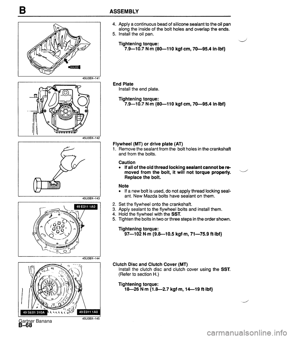
B ASSEMBLY 4. Apply a continuous bead of silicone sealant to the oil pan along the inside of the bolt holes and overlap the ends. 5. Install the oil pan. ij Tightening torque: 7.9-10.7 N.m (80-110 kgf-cm, 70-95.4 in4bf) End Plate Install the end plate. Tightening torque: 7.9--10.7 N.m (80-110 kgf.cm, 70-95.4 in-lbf) Flywheel (MT) or drive plate (AT) 1. Remove the sealant from the bolt holes in the crankshaft and from the bolts. Caution If all of the old thread locking sealant cannot be re- moved from the bolt, it will not torque properly. - Replace the bolt. Note If a new bolt is used, do not apply thread locking seal- ant. New Mazda bolts have sealant on them. 2. Set the flywheel onto the crankshaft. 3. Apply sealant to the flywheel bolts and install them. 4. Hold the flywheel with the SST. 5. Tighten the bolts in two or three steps in the order shown. Tightening torque: 97-102 N.m (9.8-10.5 kgf+m, 71-75.9 ft.lbf) Clutch Disc and Clutch Cover (MT) Install the clutch disc and clutch cover using the SST. (Refer to section H.) Tightening torque: 18-26 N.m (1.8-2.7 kgf.m, 14--19 ftlbf) Gartner Banana
Page 351 of 1708

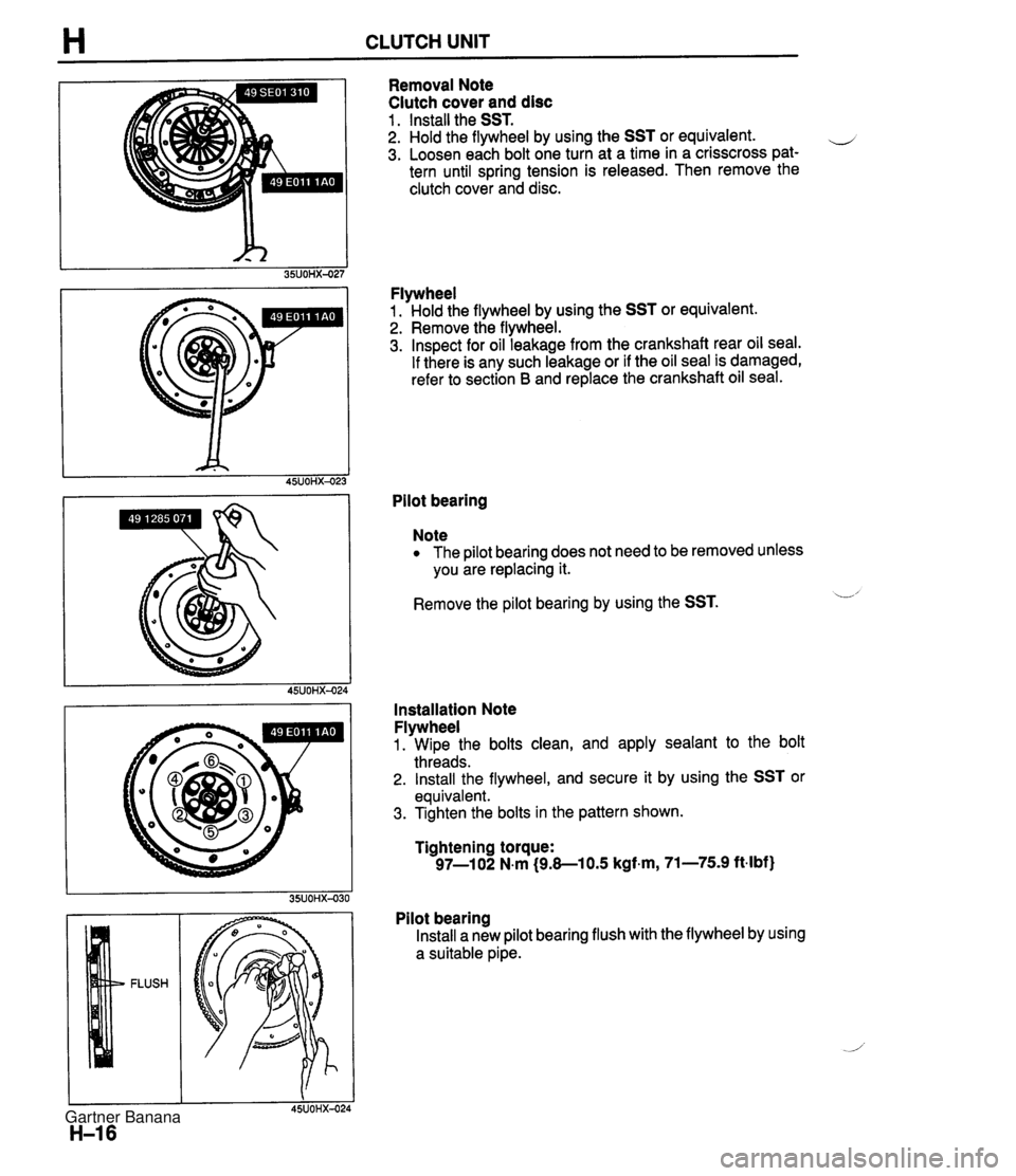
H CLUTCH UNIT Removal Note Clutch cover and disc 1 . Install the SST. 2. Hold the flywheel by using the SST or equivalent. e 3. Loosen each bolt one turn at a time in a crisscross pat- tern until spring tension is released. Then remove the clutch cover and disc. Flywheel 1. Hold the flywheel by using the SST or equivalent. 2. Remove the flywheel. 3. Inspect for oil leakage from the crankshaft rear oil seal. If there is any such leakage or if the oil seal is damaged, refer to section B and replace the crankshaft oil seal. Pilot bearing Note The pilot bearing does not need to be removed unless you are replacing it. Remove the pilot bearing by using the SST. L' Installation Note Flywheel 1. Wipe the bolts clean, and apply sealant to the bolt threads. 2. Install the flywheel, and secure it by using the SST or equivalent. 3. Tighten the bolts in the pattern shown. Tightening torque: 97-1 02 N.m (9.8-1 0.5 kgf.m, 71-75.9 ft-lbf) Pilot bearing Install a new pilot bearing flush with the flywheel by using a suitable pipe. Gartner Banana
Page 352 of 1708

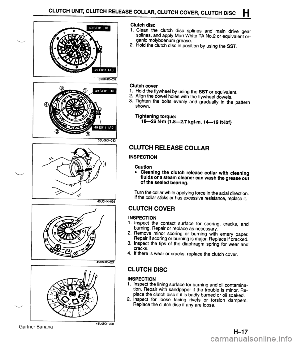
CLUTCH UNIT, CLUTCH RELEASE COLLAR, CLUTCH COVER, CLUTCH DlSC H Clutch disc 1. Clean the clutch disc splines and main drive gear splines, and apply Mori White TA No.2 or equivalent or- ganic molybdenum grease. 2. Hold the clutch disc in position by using the SST. Clutch cover 1. Hold the flywheel by using the SST or equivalent. 2. Align the dowel holes with the flywheel dowels. 3. Tighten the bolts evenly and gradually in the pattern shown. Tightening torque: 18-26 N.m (1.8-2.7 kgf.m, 14--19 ft.lbf} CLUTCH RELEASE COLLAR INSPECTION Caution Cleaning the clutch release collar with cleaning fluids or a steam cleaner can wash the grease out of the sealed bearing. Turn the collar while applying force in the axial direction. If the collar sticks or has excessive resistance, replace it. CLUTCH COVER INSPECTION 1. lnspect the contact surface for scoring, cracks, and burning. Repair or replace as necessary. 2. Remove minor scoring or burning with emery paper. Repair if scoring or burning is major. Replace if cracked. 3. lnspect the tips of the diaphragm spring for wear and cracks. 4. If there is wear or cracks, replace the clutch cover. I I 45UOHX-027 CLUTCH DlSC INSPECTION 1. lnspect the lining surface for burning and oil contamina- tion. Repair with sandpaper if the trouble is minor. Re- place the clutch disc if it is badly burned or oil soaked. 2. lnspect for loose facing rivets or torsion dampers. Replace the clutch disc if any are loose. Gartner Banana
Page 594 of 1708

FRONT AXLE M Hub bolts Note The hub bolts do not need to be removed unless you are replacing them. Remove the hub bolts with a press. Assembly note Hub bolts Install the new hub bolts with a press. Sensor rotor (ABS) Install a new sensor rotor by using the SST and a press. Inspection Front wheel hub assembly Inspect for damage. Gartner Banana
Page 600 of 1708

REAR AXLE M I 1 Hub bolt Note The hub bolts do not need to be removed unless you are replacing them. Press out the hub bolts. Assembly note Hub bolt Press in new hub bolts. Dust cover 1. Mark the new dust cover the same as the one that was removed. 2. Align the marks of the new dust cover and the knuckle. 3. Install the new dust cover by using the SST. Wheel bearing Press the new wheel bearing into the knuckle by using the SST. Gartner Banana
Page 615 of 1708

M DIFFERENTIAL Installation note Differential 1. Connect the drive shaft to the output shaft with the marks aligned. 2. Install the differential. - JOMX- Tightening torque 0: 83-98 N-m (8.5-10 kgf.m, 61-72 ft4bf) @I: 18-26 N.m (1.8-2.7 kgf.m, 13-20 ft.lbf) 3. Adjust the rear wheel alignment if the upper arm installa- tion bolt and nut were removed. (section R.) Power plant frame (PPF) 1. Install the differential mounting spacer. Tightening torque: 37-52 N-m (3.8-5.3 kgf.m, 27-38 ftdbf} .i 2. Support the transmission with a jack so that it is level. 3. Position the PPF and snugly tighten the transmission- side bolts by hand. 4. Verify that the sleeve is installed into the block. 5. Install the spacer and bolts and snugly tighten them. The reamer bolt should be installed in the forward hole. 6. Snugly install the power plant frame bracket. 7. Tighten the transmission-side bolts. Tightening torque: lO4--123 N.m (1 0.6-1 2.6 kgf.m, 77-91 ft4bf) Gartner Banana
Page 632 of 1708

MANUAL STEERING TROUBLESHOOTING GUIDE Problem Steering heavy Posslble Cause Poor lubrication, foreign material, or abnormal wear of steering ball joint Stuck or damaged lower arm ball joints lmproper steering pinion preload Damaged steering gear Malfunction of steering shaft joint lmproperly adjusted wheel alignment Malfunctioning steering gear Replace Replace gear Replace Replace Adjust Replace ~ction- Lubricate or replace section R N-12 N-12 N- 9 section R N-12 ~i&d~ection N-13 General instability while driving Steering wheel pulls to one side Shake (Steering wheel vibrates upidown) Worn or damaged stabilizer and/or suspension arm bushings Dragging brake Loose lower arm lmproperly adjusted wheel alignment lncorrect tire pressure Damaged or unbalanced wheel Worn or damaged steering joints lmproper steering pinion preload Weak front coil spring Worn or damaged stabilizer andlor suspension arm bushings Malfunctioning shock absorber lmproperly adjusted wheel alignment Excessive tire and/or wheel runout Loose lug nuts Unbalanced wheel(s) Incorrect tire pressure Incorrect tire pressure Unevenly worn tires Weak front spring Replace Repair Tighten Adjust Adjust Adjust or replace Replace Replace gear Replace Replace Replace Adjust Replace Tighten Adjust or replace section R section P section R section R section Q section Q N- 9 N-12 section R section R section R section R section Q section Q section Q Adjust Adjust Replace Replace section Q section Q section Q section R I Cracked or worn transmission mount I Cracked or worn engine mount 1 ~e~lace I section B lncorrect tire pressure Unevenly worn tires Malfunction of shock absorber Shimmy (Steering wheel vibrates circumferentially) Excessive steering wheel play Cracked or worn steering gear mount Loose steering gear mounting bolts Stuck or damaged steering ball joint Excessive tire and/or wheel runout Loose lug nuts Unbalanced wheel(s) Adjust Replace Replace Replace Replace Tighten Replace Replace Tighten Adjust or replace section Q section Q section R section J N-12 N-12 N-13 section Q section Q section Q I Loose shock absorber mounting bolts 1 Tighten I section R Stuck or damaged lower arm ball joint Cracked or worn suspension bushings Damaged or worn front wheel bearing lmproperly adjusted front wheel alignment Worn steering gear Worn or damaged steering joints Worn or damaged suspension arm bushings Loose steering gear mounting bolts I lmproperly adjusted front wheel alignment Poor steering wheel return Replace Replace Replace Adjust Replace Replace Replace Tighten Replace Adjust Replace Adjust Worn linkage &-tie-rod ball joint lncorrect tire pressure Stuck or damaged steering joints section R section R section M section R N-12 N- 9 section R N-12 N-12 section Q N- 9 section R Abnormal noise from steering system 25UONX-00! Improper steering pinion preload Ball joint not operating smoothly Steering shaft contacting something Loose steering gear Malfunctioning steering gear Obstruction near steering column Loose steering linkage Worn steering joints Replace gear Replace Repair Tighten Replace Repair or replace Tighten or replace Replace N-12 N-13 N- 9 N-12 N-12 N- 9 N-12 N- 9 Gartner Banana
Page 636 of 1708

MANUAL STEERING , N Removal / Installation 1. Disconnect the negative battery cable. 2. Remove in the order shown in the figure, referring to Removal Note. ,, 3. Inspect all parts and repair or replace as necessary. 4. Install in the reverse order of removal. 5. Tighten all necessary nuts and bolts to the specified torque. 6. After installation, check if the horn sounds. If the horn does not sound, remove the air bag module and connect the module connectors. (Refer to section T.) 1. Air bag module 6. Lower panel Removal 1 Installation .......... section T 7. Key interlock cable (Automatic transmission) 2. Locknut 8. Intermediate shaft bolt 3. Steering wheel 9. Steering shaft w ............... Removal Note page N-10 Disassembly 1 Inspection / 4. Column cover Assembly .................. page N-10 5. Combination switch Removal / Installation .......... section T Gartner Banana
Page 637 of 1708

N MANUAL STEERING Removal Note Steering wheel Caution '. Do not try to remove the steering wheel by hitting the shaft with a hammer. The column will col- lapse. Remove the steering wheel with a suitable puller. Disassembly 1 Inspection 1 Assembly 1. Disassemble in the order shown in the figure, referring to Disassembly Note. 2. Assemble in the reverse order of disassembly, referring to Assembly Note. L 1. Steering lock mounting bolts and bracket 3. Steering shaft ................... Disassembly Note ............ page N-1 1 Inspection page N-1 1 Assembly Note .............. page N-11 4. Intermediate shaft J 2. Steering lock assembly Inspect universal joint for looseness, abnormal noise, and sticking Gartner Banana