MAZDA MX-5 1997 Factory Repair Manual
Manufacturer: MAZDA, Model Year: 1997, Model line: MX-5, Model: MAZDA MX-5 1997Pages: 514, PDF Size: 17.89 MB
Page 201 of 514
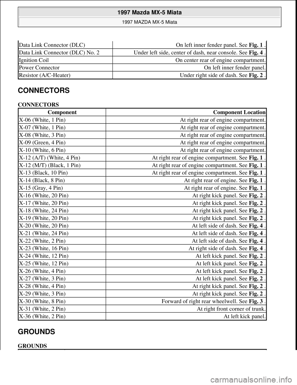
CONNECTORS
CONNECTORS
GROUNDS
GROUNDS
Data Link Connector (DLC)On left inner fender panel. See Fig. 1 .
Data Link Connector (DLC) No. 2Under left side, center of dash, near console. See Fig. 4 .
Ignition CoilOn center rear of engine compartment.
Power ConnectorOn left inner fender panel.
Resistor (A/C-Heater)Under right side of dash. See Fig. 2 .
ComponentComponent Location
X-06 (White, 1 Pin)At right rear of engine compartment.
X-07 (White, 1 Pin)At right rear of engine compartment.
X-08 (White, 3 Pin)At right rear of engine compartment.
X-09 (Green, 4 Pin)At right rear of engine compartment.
X-10 (White, 6 Pin)At right rear of engine compartment.
X-12 (A/T) (White, 4 Pin)At right rear of engine compartment. See Fig. 1 .
X-12 (M/T) (Black, 1 Pin)At right rear of engine compartment. See Fig. 1 .
X-13 (Black, 10 Pin)At right rear of engine compartment. See Fig. 1 .
X-14 (Black, 8 Pin)At right rear of engine. See Fig. 1 .
X-15 (Gray, 4 Pin)At right rear of engine. See Fig. 1 .
X-16 (White, 20 Pin)At right kick panel. See Fig. 2 .
X-17 (White, 20 Pin)At right kick panel. See Fig. 2 .
X-18 (White, 24 Pin)At right kick panel. See Fig. 2 .
X-19 (White, 20 Pin)At right kick panel. See Fig. 2 .
X-20 (White, 20 Pin)At left side of dash. See Fig. 4 .
X-21 (White, 24 Pin)At left side of dash. See Fig. 4 .
X-22 (White, 2 Pin)At left side of dash. See Fig. 4 .
X-23 (White, 16 Pin)At right side of dash. See Fig. 4 .
X-24 (White, 12 Pin)At left kick panel. See Fig. 2 .
X-25 (White, 12 Pin)At left kick panel. See Fig. 2 .
X-26 (White, 4 Pin)At left kick panel. See Fig. 2 .
X-27 (White, 3 Pin)At left kick panel. See Fig. 2 .
X-28 (White, 4 Pin)At right kick panel. See Fig. 2 .
X-29 (White, 3 Pin)At right kick panel. See Fig. 2 .
X-30 (White, 8 Pin)Forward of right rear wheelwell. See Fig. 3 .
X-31 (White, 2 Pin)At right front corner of trunk.
X-36 (White, 2 Pin)At left kick panel.
1997 Mazda MX-5 Miata
1997 MAZDA MX-5 Miata
Microsoft
Sunday, July 05, 2009 1:54:00 PMPage 4 © 2005 Mitchell Repair Information Company, LLC.
Page 202 of 514
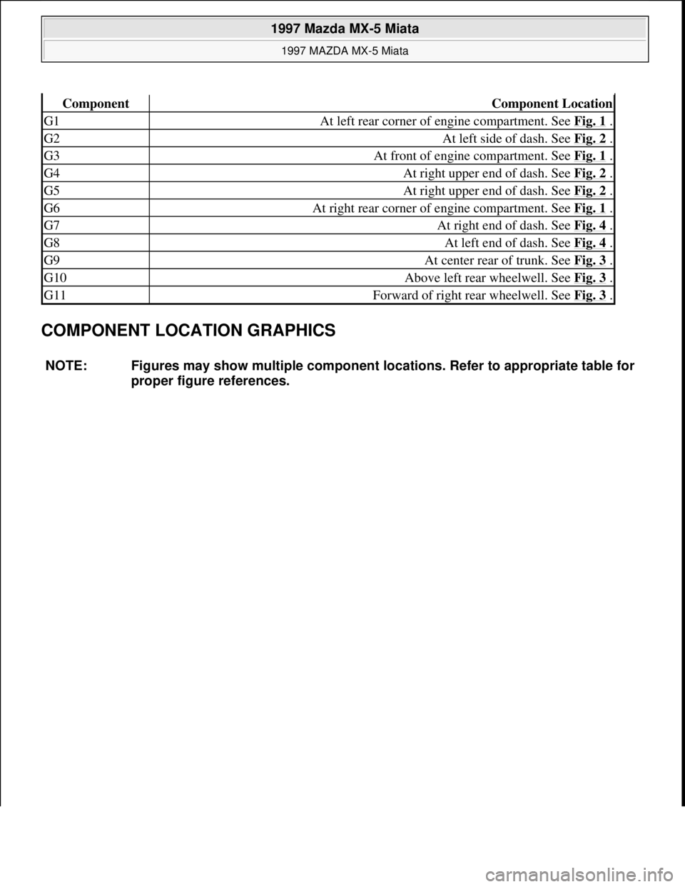
COMPONENT LOCATION GRAPHICS
ComponentComponent Location
G1At left rear corner of engine compartment. See Fig. 1 .
G2At left side of dash. See Fig. 2 .
G3At front of engine compartment. See Fig. 1 .
G4At right upper end of dash. See Fig. 2 .
G5At right upper end of dash. See Fig. 2 .
G6At right rear corner of engine compartment. See Fig. 1 .
G7At right end of dash. See Fig. 4 .
G8At left end of dash. See Fig. 4 .
G9At center rear of trunk. See Fig. 3 .
G10Above left rear wheelwell. See Fig. 3 .
G11Forward of right rear wheelwell. See Fig. 3 .
NOTE: Figures may show multiple component locations. Refer to appropriate table for
proper figure references.
1997 Mazda MX-5 Miata
1997 MAZDA MX-5 Miata
Microsoft
Sunday, July 05, 2009 1:54:00 PMPage 5 © 2005 Mitchell Repair Information Company, LLC.
Page 203 of 514
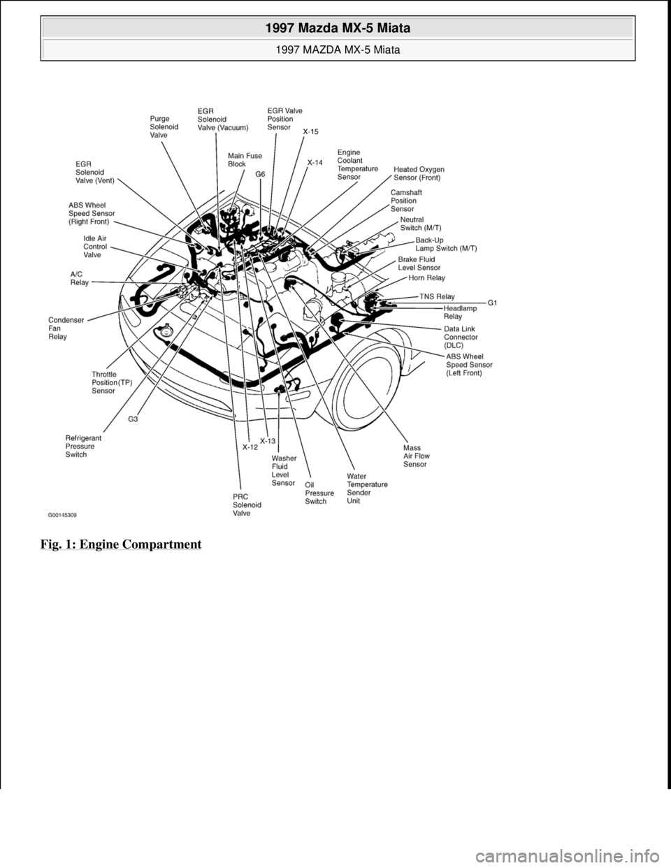
Fig. 1: Engine Compartment
1997 Mazda MX-5 Miata
1997 MAZDA MX-5 Miata
Microsoft
Sunday, July 05, 2009 1:54:00 PMPage 6 © 2005 Mitchell Repair Information Company, LLC.
Page 204 of 514
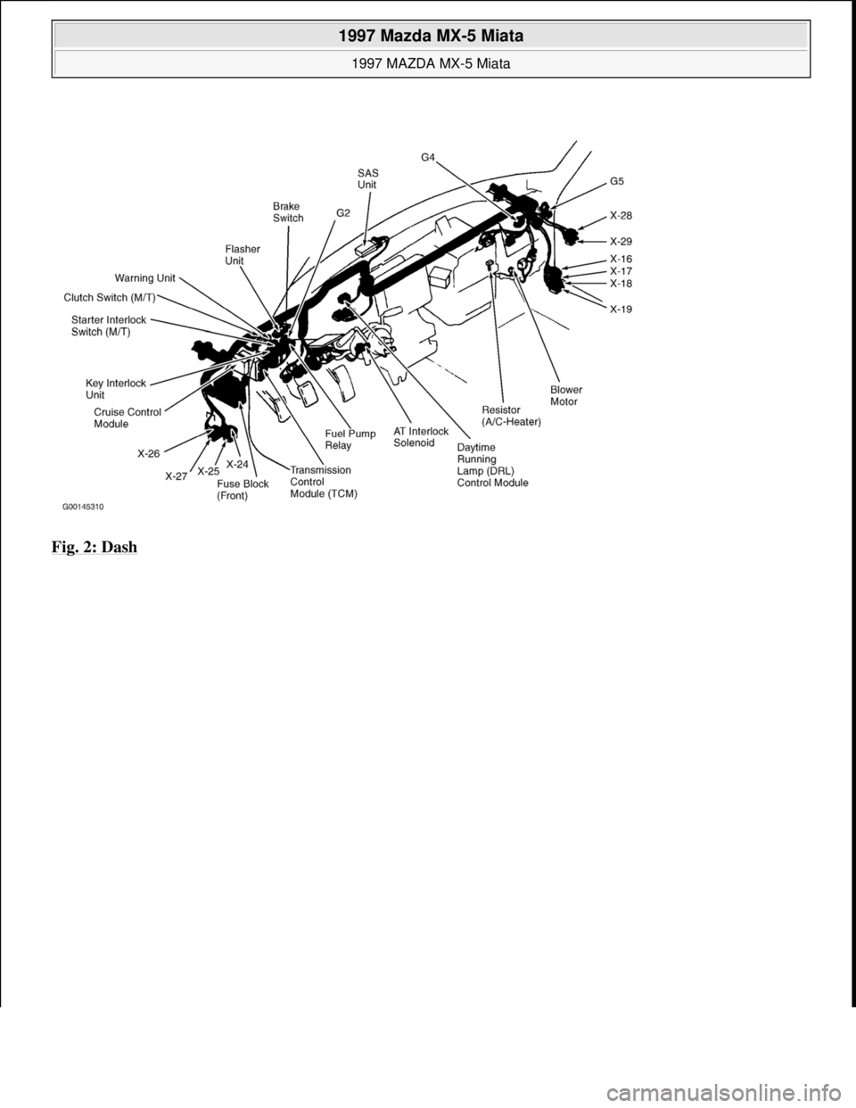
Fig. 2: Dash
1997 Mazda MX-5 Miata
1997 MAZDA MX-5 Miata
Microsoft
Sunday, July 05, 2009 1:54:00 PMPage 7 © 2005 Mitchell Repair Information Company, LLC.
Page 205 of 514
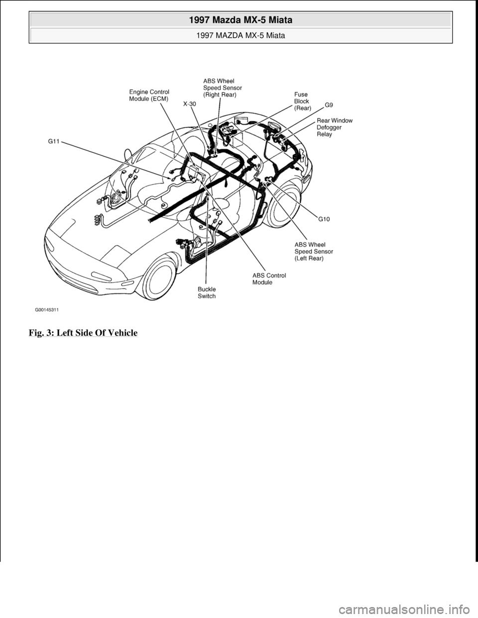
Fig. 3: Left Side Of Vehicle
1997 Mazda MX-5 Miata
1997 MAZDA MX-5 Miata
Microsoft
Sunday, July 05, 2009 1:54:00 PMPage 8 © 2005 Mitchell Repair Information Company, LLC.
Page 206 of 514
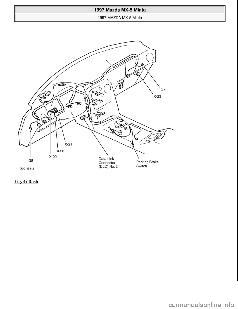
Fig. 4: Dash
1997 Mazda MX-5 Miata
1997 MAZDA MX-5 Miata
Microsoft
Sunday, July 05, 2009 1:54:00 PMPage 9 © 2005 Mitchell Repair Information Company, LLC.
Page 207 of 514
1997-98 ENGINES
1.8L 4-Cylinder
ENGINE IDENTIFICATION
Engines can be identified by engine model and number. See ENGINE IDENTIFICATION CODE. On Miata,
engine model and number are stamped on flange at upper right rear of cylinder block deck, as viewed from
flywheel. On Protege, engine model and number are stamped on flange at upper left rear of cylinder block deck,
as viewed from flywheel.
ENGINE IDENTIFICATION CODE
ADJUSTMENTS
VALVE CLEARANCE ADJUSTMENT
REMOVAL & INSTALLATION
FUEL PRESSURE RELEASE & PRIMING
Releasing Pressure (Miata)
Locate and remove fuel pump relay from under left side of dash, near steering column. Start engine and allow to
stall. After engine stalls, attempt to restart engine to ensure no residual pressure exists. Turn ignition off and
reinstall fuel pump relay. When disconnecting fuel hoses, cover connection with shop rag to catch fuel leakage.
To avoid excessive cranking after servicing, prime fuel system before starting engine.
Releasing Pressure (Protege)
NOTE: For repair procedures not covered in this article, see ENGINE OVERHAUL
PROCEDURES article in GENERAL INFORMATION.
ApplicationCode
Miata & Protege (1.8L DOHC)BP
NOTE: Valve clearance is not adjustable. Some Hydraulic Lash Adjuster (HLA) noise
may occur during engine start-up. Noise should disappear after engine reaches
normal operating temperature. If noise persists and oil level is okay, change
engine oil. If oil change does not reduce noise, check with manufacturer for
modified HLA.
NOTE: For reassembly reference, label all electrical connectors, vacuum hoses and
fuel lines before removal. Also place mating marks on engine hood and other
major assemblies before removal.
1997 Mazda MX-5 Miata
1997-98 ENGINES 1.8L 4-Cylinder
1997 Mazda MX-5 Miata
1997-98 ENGINES 1.8L 4-Cylinder
Microsoft
Sunday, July 05, 2009 1:55:15 PMPage 1 © 2005 Mitchell Repair Information Company, LLC.
Microsoft
Sunday, July 05, 2009 1:55:19 PMPage 1 © 2005 Mitchell Repair Information Company, LLC.
Page 208 of 514
Remove rear seat cushions. Disconnect fuel pump connector. Start engine and allow to stall. After engine stalls,
attempt to restart engine to ensure no residual pressure exists. Turn ignition off and reconnect fuel pump
connector. When disconnecting fuel hoses, cover connection with shop rag to catch fuel leakage. To avoid
excessive cranking after servicing, prime fuel system before starting engine.
Priming System
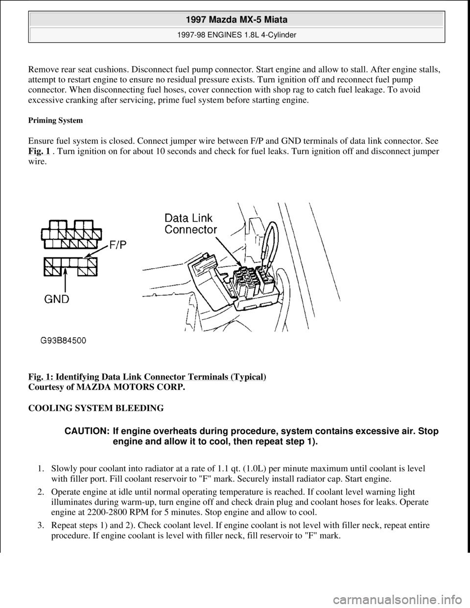
Ensure fuel system is closed. Connect jumper wire between F/P and GND terminals of data link connector. See
Fig. 1
. Turn ignition on for about 10 seconds and check for fuel leaks. Turn ignition off and disconnect jumper
wire.
Fig. 1: Identifying Data Link Connector Terminals (Typical)
Courtesy of MAZDA MOTORS CORP.
COOLING SYSTEM BLEEDING
1. Slowly pour coolant into radiator at a rate of 1.1 qt. (1.0L) per minute maximum until coolant is level
with filler port. Fill coolant reservoir to "F" mark. Securely install radiator cap. Start engine.
2. Operate engine at idle until normal operating temperature is reached. If coolant level warning light
illuminates during warm-up, turn engine off and check drain plug and coolant hoses for leaks. Operate
engine at 2200-2800 RPM for 5 minutes. Stop engine and allow to cool.
3. Repeat steps 1) and 2). Check coolant level. If engine coolant is not level with filler neck, repeat entire
procedure. If engine coolant is level with filler neck, fill reservoir to "F" mark.
CAUTION: If engine overheats during procedure, system contains excessive air. Stop
engine and allow it to cool, then repeat step 1).
1997 Mazda MX-5 Miata
1997-98 ENGINES 1.8L 4-Cylinder
Microsoft
Sunday, July 05, 2009 1:55:15 PMPage 2 © 2005 Mitchell Repair Information Company, LLC.
Page 209 of 514
ENGINE
Removal (Miata)
1. Release residual pressure from fuel system. See FUEL PRESSURE RELEASE & PRIMING .
Disconnect negative battery cable from trunk-mounted battery. Reference mark and remove hood. Raise
vehicle and remove engine undercover. See Fig. 2
. Drain engine, transmission and cooling system fluids.
2. Remove transmission. For automatic transmission removal procedure, see REMOVAL &
INSTALLATION article in TRANSMISSION SERVICING. For manual transmission removal
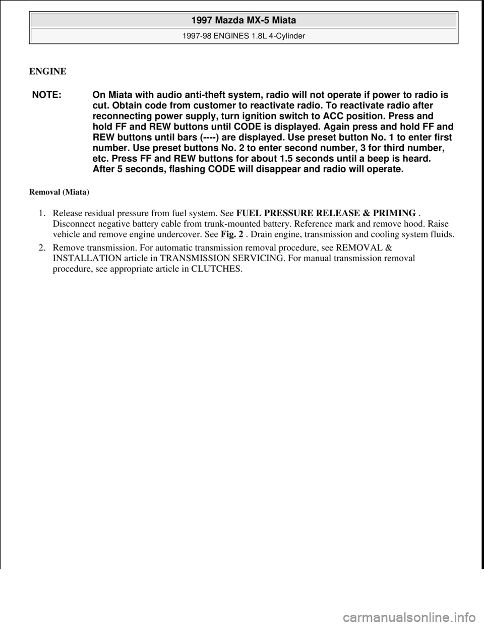
procedure, see appropriate article in CLUTCHES. NOTE: On Miata with audio anti-theft system, radio will not operate if power to radio is
cut. Obtain code from customer to reactivate radio. To reactivate radio after
reconnecting power supply, turn ignition switch to ACC position. Press and
hold FF and REW buttons until CODE is displayed. Again press and hold FF and
REW buttons until bars (----) are displayed. Use preset button No. 1 to enter first
number. Use preset buttons No. 2 to enter second number, 3 for third number,
etc. Press FF and REW buttons for about 1.5 seconds until a beep is heard.
After 5 seconds, flashing CODE will disappear and radio will operate.
1997 Mazda MX-5 Miata
1997-98 ENGINES 1.8L 4-Cylinder
Microsoft
Sunday, July 05, 2009 1:55:15 PMPage 3 © 2005 Mitchell Repair Information Company, LLC.
Page 210 of 514
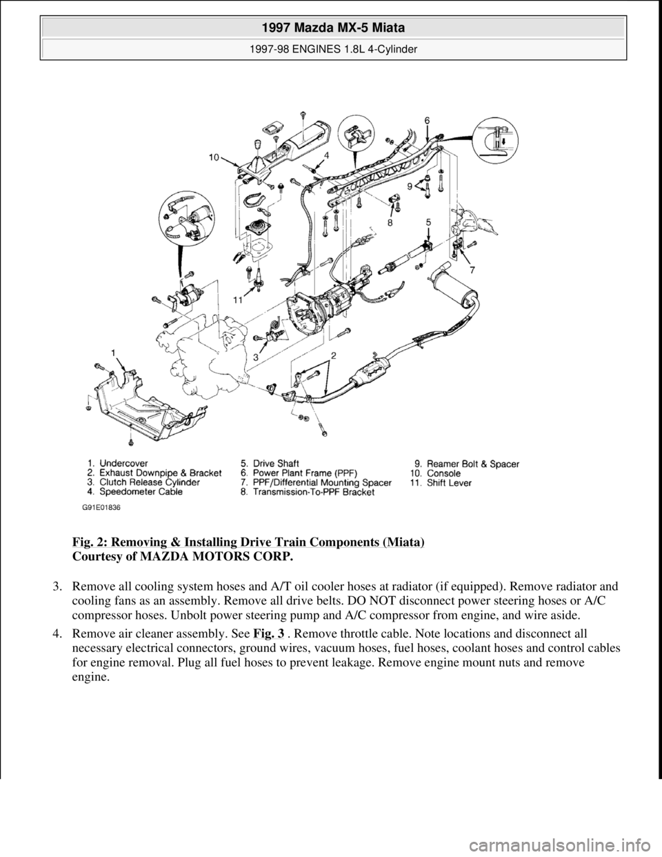
Fig. 2: Removing & Installing Drive Train Components (Miata)
Courtesy of MAZDA MOTORS CORP.
3. Remove all cooling system hoses and A/T oil cooler hoses at radiator (if equipped). Remove radiator and
cooling fans as an assembly. Remove all drive belts. DO NOT disconnect power steering hoses or A/C
compressor hoses. Unbolt power steering pump and A/C compressor from engine, and wire aside.
4. Remove air cleaner assembly. See Fig. 3
. Remove throttle cable. Note locations and disconnect all
necessary electrical connectors, ground wires, vacuum hoses, fuel hoses, coolant hoses and control cables
for engine removal. Plug all fuel hoses to prevent leakage. Remove engine mount nuts and remove
en
gine.
1997 Mazda MX-5 Miata
1997-98 ENGINES 1.8L 4-Cylinder
Microsoft
Sunday, July 05, 2009 1:55:15 PMPage 4 © 2005 Mitchell Repair Information Company, LLC.