wheel alignment MAZDA PROTEGE 1992 Workshop Manual
[x] Cancel search | Manufacturer: MAZDA, Model Year: 1992, Model line: PROTEGE, Model: MAZDA PROTEGE 1992Pages: 1164, PDF Size: 81.9 MB
Page 20 of 1164
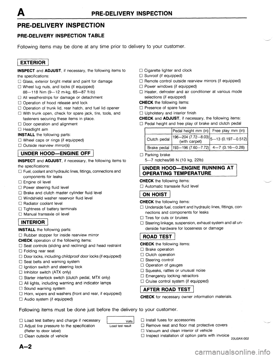
PRE-DELIVERY INSPECTION
PRE-DELIVERY INSPECTION
PRE-DELIVERY INSPECTION TABLE
Following items may be done at any time prior to delivery to your customer.
INSPECT and ADJUST, if necessary, the following items to
the specifications:
0 Glass, exterior bright metal and paint for damage
Cl Wheel lug nuts, and locks (if equipped)
88-118 N.m (9-12 m-kg, 65-87 ft-lb)
q All weatherstrips for damage or detachment
0 Operation of hood release and lock
0 Operation of trunk lid, rear hatch, and fuel lid opener
Cl With trunk open, check for spare jack, tire, tools, and
fasteners securing these items in place.
Cl Door operation and alignment
Cl Headlight aim
INSTALL the following parts:
Cl Wheel caps or rings (if equipped)
q Outside rearview mirror(s)
1 UNDER HOOD-ENGINE OFF )
INSPECT and ADJUST, if necessary, the following items to
the specifications:
0 Fuel, coolant and hydraulic lines, fittings, connections and
components for leaks
Cl Engine oil level
0 Power steering fluid level
0 Brake and clutch master cylinder fluid level
El Windshield washer reservoir fluid level
Cl Radiator coolant level
Cl Tightness of battery terminals
Cl Manual transaxle oil level
riizmiq
INSTALL the following parts:
Cl Rubber stopper for inside rearview mirror
CHECK operation of the following items:
0 Seat controls (sliding and reclining) and head restraint
Cl Folding rear seat
0 Door locks, including childproof door locks (if equipped)
Seat belts and warning system
Cl Ignition switch and steering lock
0 Inhibitor switch (ATX only)
U Starter interlock switch (clutch pedal, MTX only)
Cl All lights, including warning and indicator lamps
Cl Sound warning system
Cl Horn, wipers and washers (front and rear, if equipped)
0 Audio system (if equipped) 0 Cigarette lighter and clock
0 Sunroof (if equipped)
II Remote control outside rearview mirrors (if equipped)
Cl Power windows (if equipped)
q Heater, defroster and air conditioner at various mode
selections (if equipped)
CHECK the following items:
Cl Presence of spare fuse
0 Upholstery and interior finish
CHECK and ADJUST, if necessary, the following items:
0 Pedal height and free play of brake and clutch pedal
Pedal height mm (in) Free play mm (in)
0 Parking brake
5-7 notches/98 N (10 kg, 22lb)
UNDER HOOD-ENGINE RUNNING AT
OPERATING TEMPERATURE
CHECK the following items:
q Automatic transaxle fluid level
[I
CHECK the following items:
Cl Underside fuel, coolant and hydraulic lines, fittings, con-
nections and components for leaks
0 Tires for cuts or bruises
0 Steering linkage, suspension, exhaust system and all un-
derside hardware for looseness or damage
[I
CHECK the following items:
0 Brake operation
0 Clutch operation
Cl Steering control
Cl Operation of gauges
q Squeaks, rattles or unusual noise
Cl Emergency locking retractors
0 Cruise control system (if equipped)
1 AFTER ROAD TEST (
CHECK for necessary owner information materials.
Following items must be done just before the delivery to your customer.
q Load test battery and charge if necessary
1 Volts 1 0 Install fuses for accessories
i.. _
0 Adjust tire pressure to the specification
Load test result cl Remove seat and floor mat protective covers
(Refer to door label) 0 Vacuum and clean interior of vehicle
0 Clean outside of vehicle q Inspect installation of option parts with invoice
23UOAX-002
A-2
Page 601 of 1164

FRONT AXLE M
WHEEL HUB, STEERING KNUCKLE
Preinspection
Wheel bearing play
1. Remove the wheel and tire.
2. Remove the brake caliper assembly and disc plate.
3. Position a dial indicator against the wheel hub. Push and
pull the wheel hub by hand in the axial direction and meas-
ure the wheel bearing play.
4. If the bearing play exceeds specification, check and adjust
the locknut torque or replace the wheel bearing if necessary.
Removal / Installation
d Maximum wheel bearing play: 0.05mm (0.002 in)
1. Remove in the order shown in the figure, referring to Removal Note.
2. Inspect all parts and repair or replace as necessary.
3. Install in the reverse order of removal, referring to
Installation Note.
4. After installation, check the front wheel alignment. (Refer to Section R.)
SERVIC\E, SECTION R
7 93--12? W.-L%” COTiER PIN, REPLACE
(9.5-12.9, 69-S
39-54
(4.0-5.6, 29-40) 39-64 ’ 236-319 (24.0-32.5, 174-235)
(4.4-6.0, 32-43)
66-67)
N.m (m-kg, it-lb)
23UOMX-006
1. Wheel and tire
2. Locknut
Installation Note . . . . . . . . . . . . . . . . . . . . . . . . . page M- 6
3. Brake caliper assembly
Service . . . . . . . . . . . . . . . . . . . . . . . . . . . . . . . . . . . . . . . . . . Section P
4. Disc plate
Inspection . . . . . . . . . . . . . . . . . . . . . . . . . . . . . . . . . . . . . . Section P
5. Tie rod end
Removal Note . . . . . . . . . . . . . . . . . . . . . . . . . . . . page M- 6
Installation Note . . . . . . . . . . . . . . . . . . . . . . . . . page M- 6 6. Lower ball joint
7. Knuckle, wheel hub, and dust cover
Inspect wheel hub for cracks and damage
Inspect knuckle spindle for cracks and
damage
Inspect dust cover for damage and dis-
tortion
Disassembly / Inspection I
Assembly . . . . . . . . . . . . . . . . . . . . . . . . . . . . . . . . . page M- 7
M-5
Page 607 of 1164

REAR AXLE M
L.3”“I”lh-” I
Removal / Inspection / Installation
1. Remove in the order shown in the figure, referring to Removal Note.
2. Inspect all parts and repair or replace as necessary.
3. Install in the reverse order of removal, referring to
Installation Note.
4. After installation, bleed the brake system, adjust the parking brake lever stroke (Refer to Section P.) and
DRUM BRAKE TYPE
Preinspection
Wheel bearing play
1. Remove the wheel and tire.
2. Position a dial indicator against the brake drum. Push and
pull the rear brake assembly by hand in the axial direction
and measure the wheel bearing play.
3. If the bearing play exceeds specification, check and adjust
the locknut torque or replace the wheel bearing if necessary.
Maximum wheel bearing play: 0.05mm (0.002 in)
66-l 17 (6.7-l 1.9, 63-66)
45-59
(4.6:6.0, 33-43)
check the rear wheel alignment (Refer to Section R.)
SEiWICE, SECTION R /
I
GA
19-26 (1.9-2.6, 14-19)
177-235
(16.0-24.0, 130-174) d
REPLACE REPLACE
(9.0-12.0,
65-67)
N.m (m-kg, ft-lb)
7RI ImAX-ni
J 3
1. Wheel and tire
2. Hub cap
3. Locknut
Installation Note . . . . . . . . . . . . . . . . . . . . . . . . . page M-l 2
4. Brake drum
5. Hub bearing assembly
Inspect for cracks and damage
Disassembly I Assembly . . . . . . . . . . . . page M-l 3 6. Parking brake cable
Service . . . . . . . . . . . . . . . . . . . . . . . . . . . . . . . . . . . . . . Section P
7. Brake pipe
Removal Note .,.......................... page M-12
Installation Note . . . . . . . . . . . . . . . . . . . . . . . . . page M-l 2
8. Rear brake assembly
Service ,,........................................ Section P
9. Rear spindle
Inspect for cracks and damage
M-l 1
Page 671 of 1164
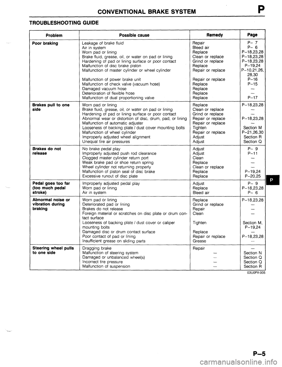
CONVENTIONAL BRAKE SYSTEM
TROUBLESHOOTING GUIDE
Problem Possible cause Remedy Page
Poor braking
Leakage of brake fluid Repair P- 7
Air in system Bleed air P- 6
Worn pad or lining Replace P-l 8,23,28
Brake fluid, grease, oil, or water on pad or lining Clean or replace P-18,23,28
Hardening of pad or lining surface or poor contact Grind or replace P-l 8,23,28
Malfunction of disc brake piston Replace P-l 9,24
Malfunction of master cylinder or wheel cylinder Repair or replace P-l 0,21,26,
28,30
Malfunction of power brake unit Repair or replace P-16
Malfunction of check valve (vacuum hose) Replace P-15
Damaged vacuum hose Replace -
Deterioration of flexible hose Replace -
Malfunction of dual proportioning valve Replace P-17 Brakes pull to one
Worn pad or lining Replace P-l 8,23,28 side Brake fluid, grease, oil, or water on pad or lining Clean or replace -
Hardening of pad or lining surface or poor contact Grind or replace
Abnormal wear or distortion of disc, drum, pad, or lining Repair or replace P-l 8;3,28
Malfunction of automatic adjuster Repair or replace -
Looseness of backing plate I dust cover mounting bolts Tighten Section M
Malfunction of wheel cylinder Repair or replace P-21,26,30
Improperly adjusted wheel alignment Adjust Section R
Unequal tire air pressures
Adjust Section Q Brakes do not
No brake pedal play Adjust P- 9 release Improperly adjusted push rod clearance Adjust P-11
Clogged master cylinder return port Clean -
Weak brake pad or shoe return spring Replace -
Wheel cylinder not returning properly
Clean or replace
Malfunction of piston seal of disc brake Replace P-l;,24
Excessive runout of disc plate
Replace P-20,25 Pedal goes too far
Improperly adjusted pedal play Adjust P- 9 (too much pedal Worn pad or lining
Replace P-18,23,28 stroke) Air in system
Bleed air P- 6 Abnormal noise or
Worn pad or lining
Replace P-18,23,28 vibration during Deteriorated pad or lining Grind or replace - braking Brakes do not release Repair -
Foreign material or scratches on disc plate or drum con- Clean -
tact surface
Looseness of backing plate / dust cover or caliper Tighten
Section M,
mounting bolts P-l 9,24
Damaged disc or drum contact surface Replace -
Poor contact of pad or fining Repair or replace
P-18,23,28
Insufficient grease on sliding parts Grease - Steering wheel pulls
Dragging brake Repair - to one side Malfunction of steering system -
Section N
Damaged or unbalanced wheel(s) -
Section Cl
Incorrect tire pressure -
Section Q
Malfunction of suspension -
Section R
mm> IAn\, ,.e
P-5
Page 707 of 1164
R
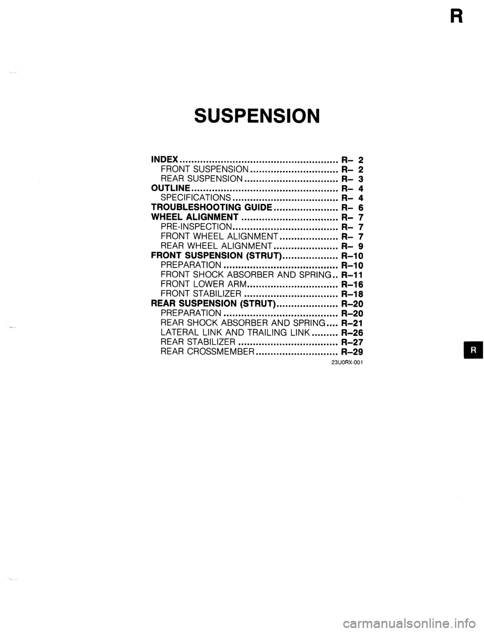
SUSPENSION
INDEX ...................................................... R- 2
FRONT SUSPENSION ..............................
R- 2
REAR SUSPENSION ................................ R- 3
OUTLINE .................................................. R- 4
SPECIFICATIONS ....................................
TROUBLESHOOTING GUIDE.. .................... ;I ;
WHEEL ALIGNMENT ................................. R- 7
PRE-INSPECTION ....................................
FRONT WHEEL ALIGNMENT.. .................. ;I ;
REAR WHEEL ALIGNMENT.. .................... R- 9
FRONT SUSPENSION (STRUT). .................. R-l 0
PREPARATION ....................................... R-l 0
FRONT SHOCK ABSORBER AND SPRING . . R-11
FRONT LOWER ARM
............................... R-l 6
FRONT STABILIZER ................................
R-l 6
REAR SUSPENSION (STRUT). .................... R-20
PREPARATION ....................................... R-20
REAR SHOCK ABSORBER AND SPRING .... R-21
LATERAL LINK AND TRAILING LINK.. ....... R-26
REAR STABILIZER .................................. R-27
REAR CROSSMEMBER ............................ R-29
23UORX-001
Page 708 of 1164
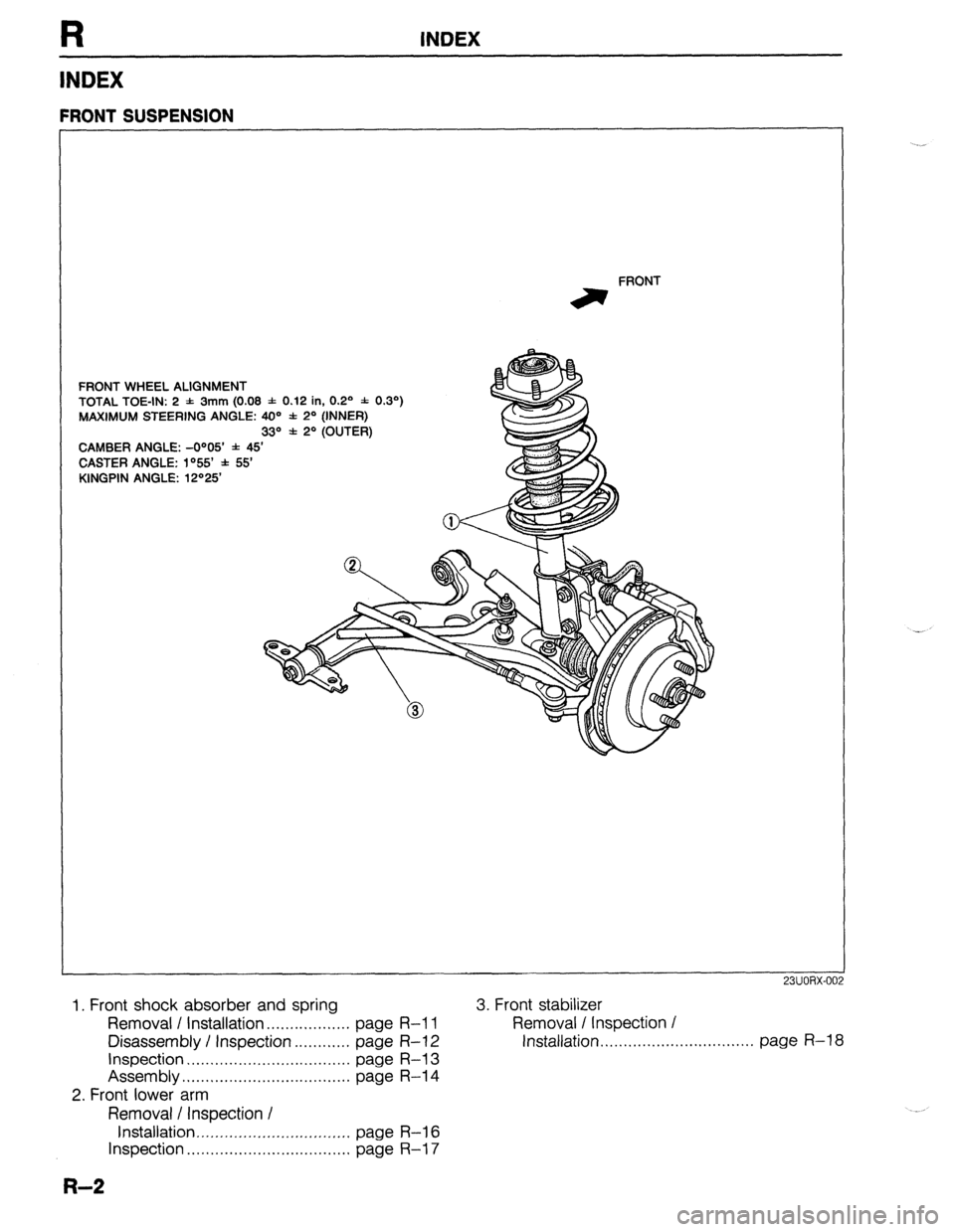
R INDEX
INDEX
FRONT WHEEL ALIGNMENT
TOTAL TOE-IN: 2 -1: 3mm (0.08 f 0.12 in, 0.2’ * 0.3’)
MAXIMUM STEERING ANGLE: 40=’ * 2’ (INNER)
33“ f 2O (OUTER)
CAMBER ANGLE: -O”05’ * 45’
CASTER ANGLE: lo55 f 55
KINGPIN ANGLE: 12“25 FRONT
irr
FRONT SUSPENSION
1. Front shock absorber and spring
Removal I Installation . . . . . . . . . . . . . . . . . . page R-l 1
Disassembly / Inspection . . . . . . . . . . . . page R-l 2
Inspection . . . . . . . . . . . . . . . . . . . . . . . . . . . . . . . . page R-l 3
Assembly . . . . . . 1 . . . . . . . . . . . . . . . . . . . . . . . . . . . . . page R-l 4
2. Front lower arm
Removal / Inspection I
Installation ,,...,.......,...........,.._..,. page R-l 6
Inspection . . . . . . . . . . . . . . . . . . . . . . . . . . . . . . . . . . . page R-l 7
R-2
3. Front stabilizer
Removal / Inspection /
Installation, . . . . . . ,. . . . . . . . . . . . . . . . . . . . . . . . . page R-l 8
Page 709 of 1164
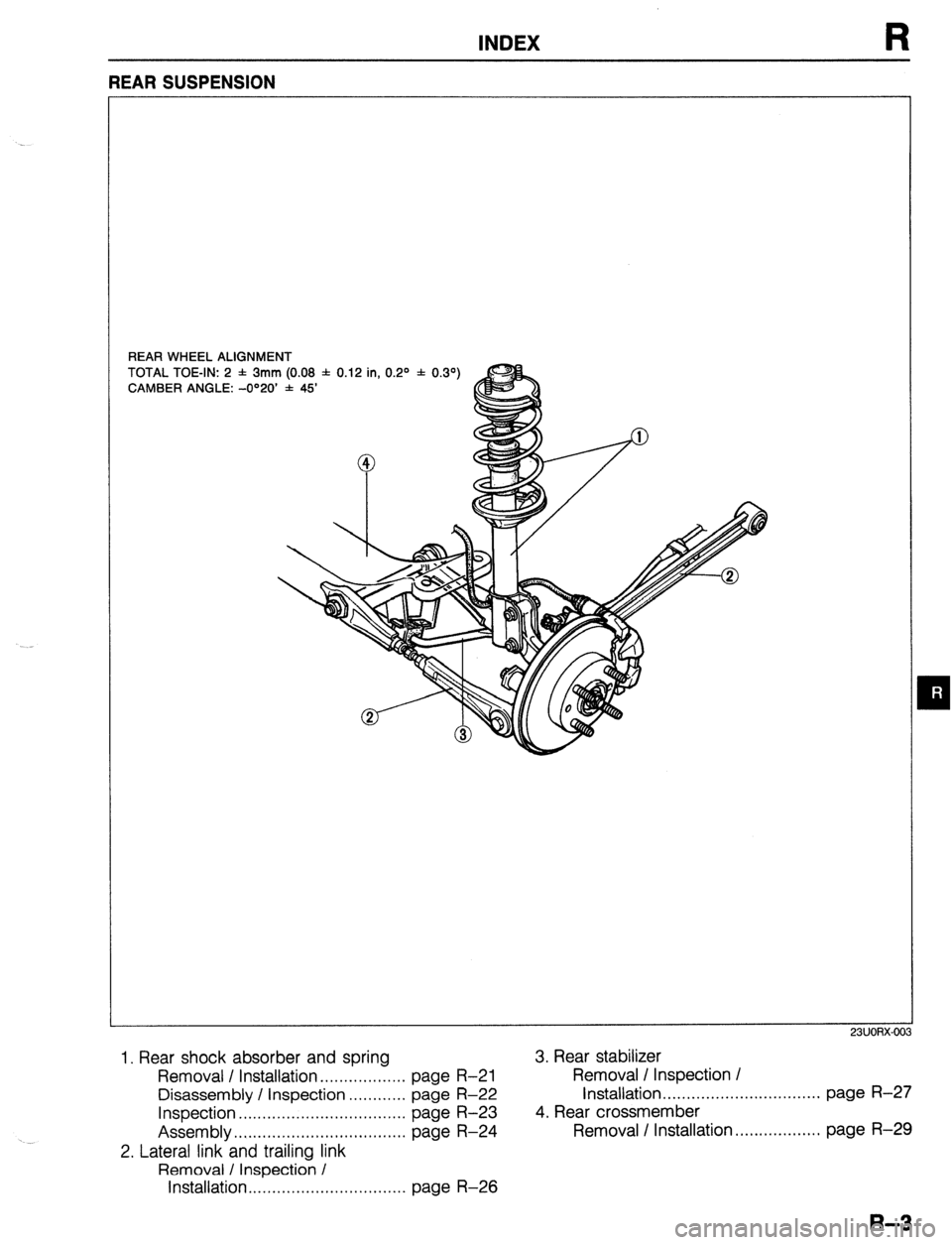
INDEX
REAR WHEEL ALIGNMENT
TOTAL TOE-IN: 2 f 3mm (0.08 f 0.12 in, 0.2O * 0.39
CAMBER ANGLE: -O”20’ * 45’
m
1. Rear shock absorber and spring 3. Rear stabilizer
Removal / Installation . . . . . . . . . . . . . . . . . . page R-21 Removal / Inspection /
Disassembly / Inspection . . . . . . . . . . . . page
R-22 Installation . . . . . . . . . . . . . . . . . . . . . . . . . . ...*... page R-27
Inspection . . . . . . . . . . . . . . . . . . . . . . . . . . . . . . . . . . . page R-23 4. Rear crossmember
Assembly.. . . . . . . . . . . . . . . . . . . . . . . . . . . . . . . . . . .
page R-24 Removal I Installation. . . . . . . . . . . . . . . . . . page R-29
2. Lateral link and trailing link
Removal / Inspection /
Installation . . . . . . . . . . . . . . . . . . . . . . . . . . . . . . . . . page R-26
Page 710 of 1164
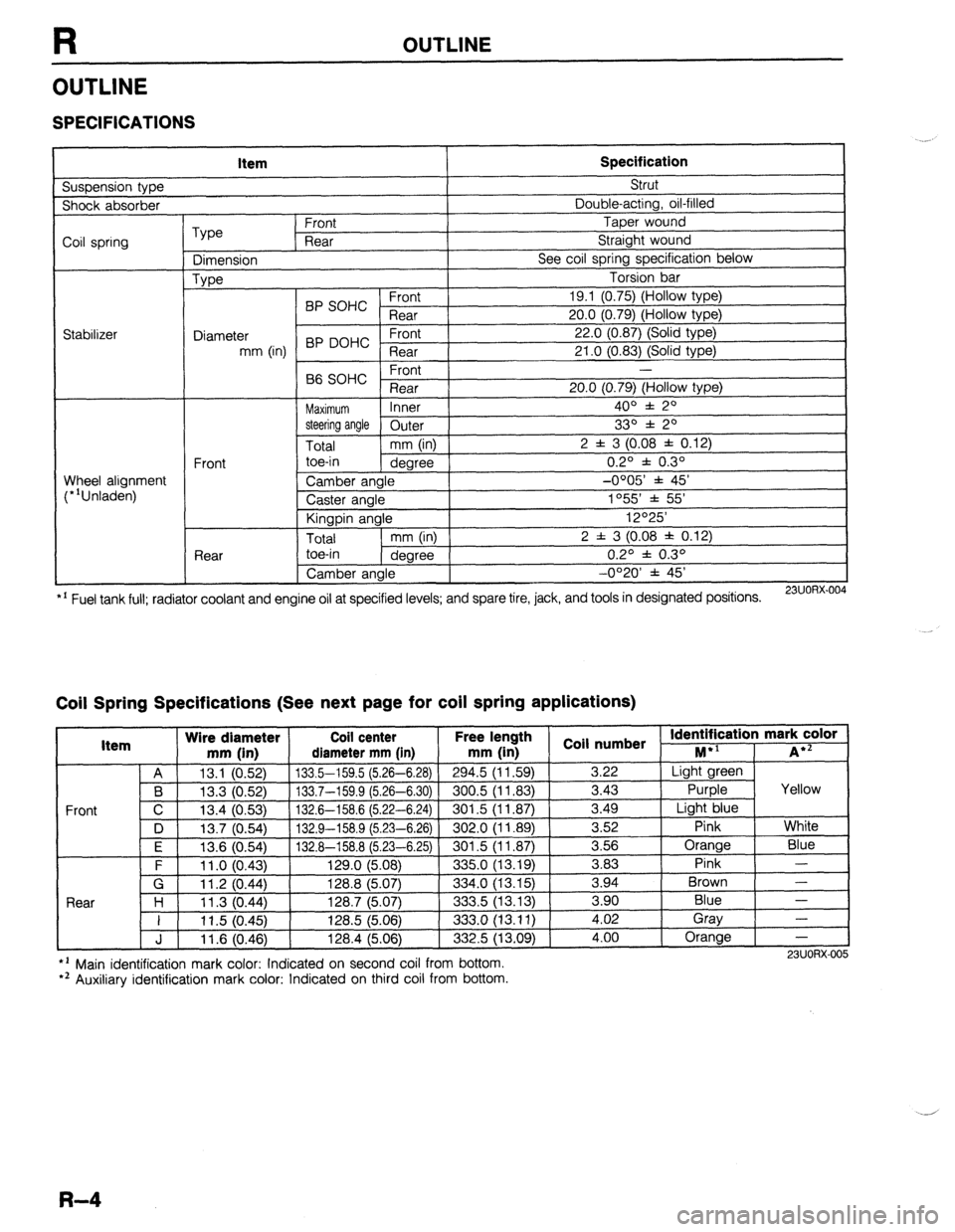
R OUTLINE
OUTLINE
SPECIFICATIONS
Suspension type Item Specification Strut
Shock absorber Double-acting, oil-filled
Coil spring
Stabilizer Type Front Taper wound
Rear Straight wound
Dimension See coil spring specification below
Type Torsion bar
BP SOHC Front 19.1 (0.75) (Hollow type)
Rear 20.0 (0.79) (Hollow type)
Diameter 22.0 (0.87) (Solid type)
mm (in) BP DOHC ;eTrt
21 .O (0.83) (Solid type)
P ,
-
66 SOHC rronr
Rear 20.0 (0.79) (Hollow type)
Maximum Inner 400 f 20
steering angle
Outer 330 f 20
Total mm (in) 2 f 3 (0.08 f 0.12)
Front toe-in
degree 0.2O f 0.3O
Wheel alignment
(*‘Unladen) Camber angle -0005’ f 45’
Caster angle 1055 * 55’
Kingpin angle 12O25’
Total mm (in) 2 f 3 (0.08 * 0.12)
Rear toe-in
degree 0.2O f 0.3O
Camber angle -0°20’ f 45’
*’ Fuel tank full; radiator coolant and engine oil at specified levels; and spare tire, jack, and tools in designated positions.
23UORX.004
Coil Spring Specifications (See next page for coil spring applications)
I Item Wire diameter Coil center Free lel.=-. .
mm iin1 rliamotor mm [in mm (in 1 coil numbs
Front
nath
1 _ . . *St Identification mark color +l
., . . . . I...,
-*.....-.“, * . . . . . ,..-, -....- I--‘, M iA*=
A 13.1 (0.52) 133.5-159.5 (5.26-6.28)
294.5 (11.59) 3.22 Light green
B 13.3 (0.52) 133.7-159.9 (5.26-6.30) 300.5 (11.83)
3.43 Purple Yellow
C 13.4 (0.53)
132.6-158.6 (5.22-6.24) 301.5 (11.87) 3.49
Light blue
D 13.7 (0.54)
132.9-158.9 (5.23-6.26) 302.0 (11.89) 3.52
Pink White
I F I 12f3 Kl5Al I 1.17 A-l!% 8 f!i PR-Fi 751
I RrIl .5 II 1 6x71 I 3.56 Orange
Blue
3 83 Pink -
Brown - .“._ \“.- .,
. “W.., ~ - -. - \-. -- -. - -, -- .-
\’ .‘-‘I t
F 11 .o (0.43) 129.0 (5.08)
335.0 (13.19) -.--
G 11.2 (0.44) 128.8 (5.07)
334.0 (13.15) 3.94
Rnnr l-4
1 I ? 07 AA 1387 /5n7
.?m !i 113 1% 3 an Blue - I I I I .” \v.-7, I&V., \V.“., ---.., \.-. .-, I 11.5 (0.45) 128.5 (5.06)
333.0 (13.11) i:oi Gray
-
J 11.6 (0.46) 128.4 (5.06)
332.5 (13.09) 4.00 Orange
-
l ’ Main identification mark color: Indicated on second coil from bottom.
*’ Auxiliary identification mark color: Indicated on third coil from bottom. 23UORX-005
R-4
Page 712 of 1164
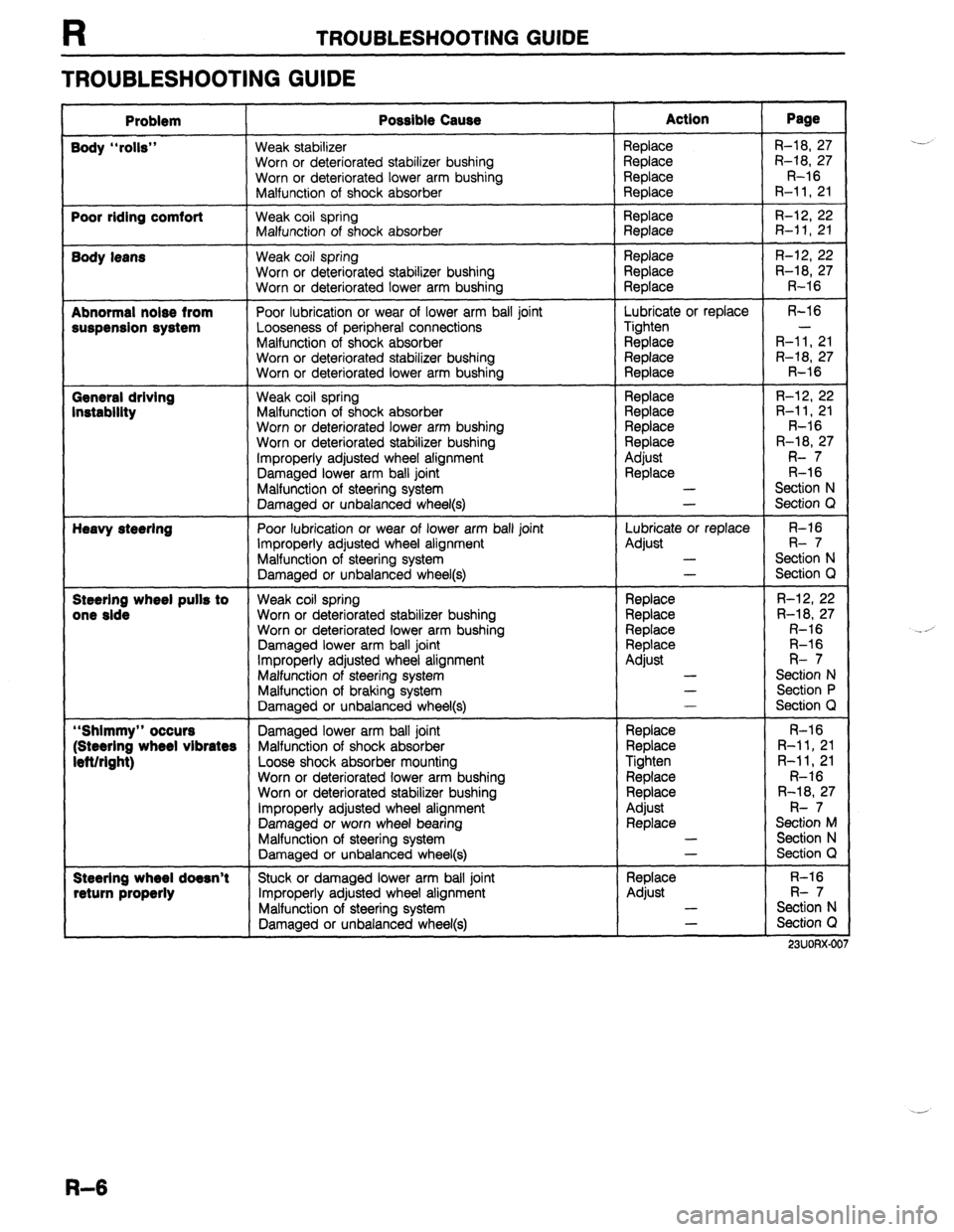
TROUBLESHOOTING GUIDE
TROUBLESHOOTING GUIDE
Problem Possible Cause Action Page
Body “rolls” Weak stabilizer Replace R-18, 27
Worn or deteriorated stabilizer bushing Replace R-18, 27
Worn or deteriorated lower arm bushing
Replace R-16
Malfunction of shock absorber
Replace R-11,21
Poor riding comfort Weak coil spring Replace R-12, 22
Malfunction of shock absorber Replace R-11,21
Body leans Weak coil spring Replace R-12, 22
Worn or deteriorated stabilizer bushing
Replace R-18, 27
Worn or deteriorated lower arm bushing Replace R-16
Abnormal noise from Poor lubrication or wear of lower arm ball joint Lubricate or replace R-16
suspension system Looseness of peripheral connections Tighten -
Malfunction of shock absorber Replace R-11, 21
Worn or deteriorated stabilizer bushing Replace R-18, 27
Worn or deteriorated lower arm bushing
Replace R-16
General driving Weak coil spring Replace R-12, 22
Instability Malfunction of shock absorber Replace R-11, 21
Worn or deteriorated lower arm bushing Replace R-16
Worn or deteriorated stabilizer bushing Replace R-18, 27
Improperly adjusted wheel alignment Adjust R- 7
Damaged lower arm ball joint
Replace R-l 6
Malfunction of steering system -
Section N
Damaged or unbalanced wheel(s) -
Section Q
Heavy steering
Poor lubrication or wear of lower arm ball joint Lubricate or replace R-16
Improperly adjusted wheel alignment
Adjust R- 7
Malfunction of steering system -
Section N
Damaged or unbalanced wheel(s) -
Section Q
Steerlng wheel pulls to Weak coil spring
Replace R-12, 22
one side
Worn or deteriorated stabilizer bushing Replace R-18, 27
Worn or deteriorated lower arm bushing Replace R-16
Damaged lower arm ball joint Replace R-16
Improperly adjusted wheel alignment Adjust R- 7
Malfunction of steering system -
Section N
Malfunction of braking system -
Section P
Damaged or unbalanced wheel(s) -
Section Q
“Shimmy” occurs Damaged lower arm ball joint Replace R-16
(Steering wheel vibrates Malfunction of shock absorber
Replace R-11, 21
left/right) Loose shock absorber mounting
Tighten R-11, 21
Worn or deteriorated lower arm bushing
Replace R-16
Worn or deteriorated stabilizer bushing Replace R-18, 27
Improperly adjusted wheel alignment
Adjust R- 7
Damaged or worn wheel bearing Replace Section M
Malfunction of steering system -
Section N
Damaged or unbalanced wheel(s) -
Section Q
Steering wheel doesn’t Stuck or damaged lower arm ball joint
Replace R-16
return properly Improperly adjusted wheel alignment Adjust R- 7
Malfunction of steering system -
Section N
Damaged or unbalanced wheel(s) -
Section Q
_-..--..__
23UUHXJJC
.-_,
.-
R-6
Page 713 of 1164
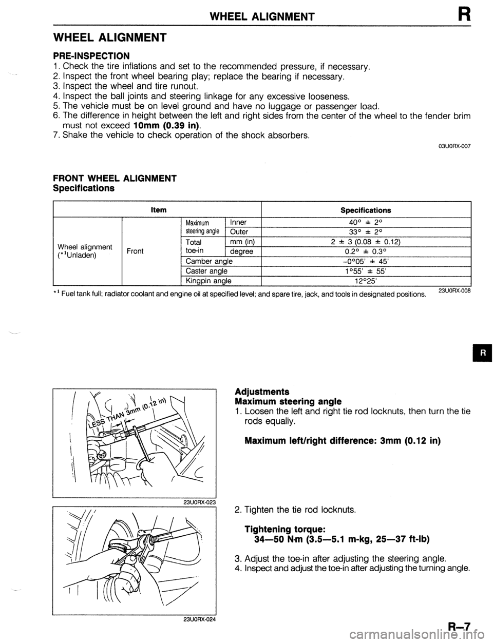
WHEEL ALIGNMENT
WHEEL ALIGNMENT
PRE-INSPECTION
1. Check the tire inflations and set to the recommended pressure, if necessary.
2. Inspect the front wheel bearing play; replace the bearing if necessary.
3. inspect the wheel and tire runout.
4. Inspect the ball joints and steering linkage for any excessive looseness.
5. The vehicle must be on level ground and have no luggage or passenger load.
6. The difference in height between the left and right sides from the center of the wheel to the fender brim
must not exceed
10mm (0.39 in).
7. Shake the vehicle to check operation of the shock absorbers.
03UORX.007
FRONT WHEEL ALIGNMENT
Specifications
item
Specifications
Maximum Inner 4o” f: 2O
steering angle Outer
33O f 2O
Total mm (in) 2 f 3 (0.08 f 0.12)
toe-in dearee 0.20 f 0.30 Wheel alignment
(*‘Unladen) Front
*I Fuel tank full; radiator coolant and Camber angle -0005 * 45’
Caster angle 1°55’ f 55’
Kingpin angle 12O25’
engine oil at specified level; and spare tire, jack, and tools in designated positions.
23UORX-008
I
I 23UORX-023
Adjustments
Maximum steering angle
1. Loosen the left and right tie rod locknuts, then turn the tie
rods equally.
Maximum left/right difference: 3mm (0.12 in)
2. Tighten the tie rod locknuts.
Tightening torque:
34-50 N-m (3.5-5.1 m-kg, 25-37 ft-lb)
3. Adjust the toe-in after adjusting the steering angle.
4. Inspect and adjust the toe-in after adjusting the turning angle.
I 23UORX-024
R-7