tow MAZDA PROTEGE 1992 Workshop Manual
[x] Cancel search | Manufacturer: MAZDA, Model Year: 1992, Model line: PROTEGE, Model: MAZDA PROTEGE 1992Pages: 1164, PDF Size: 81.9 MB
Page 3 of 1164
GENERAL INFORMATION
IMPORTANT INFORMATION ..................... GI- 2
BASIC ASSUMPTIONS ............................ GI- 2
SAFETY RISK ........................................ GI- 2
POSSIBLE LOSS OF WARRANTY ............. GI- 2
WARNING ON LUBRICANTS
AND GREASES .................................... GI- 2
HOW TO USE THIS MANUAL.. .................. GI- 3
PREPARATION ...................................... GI- 3
REPAIR PROCEDURE ............................. GI- 3
SYMBOLS ............................................. GI- 4
NOTES, CAUTIONS, AND WARNINGS.. ..... GI- 4
FUNDAMENTAL PROCEDURES.. ............... GI- 4
PROTECTION OF THE VEHICLE .............. GI- 4
A WORD
ABOUT SAFETY ....................... GI- 5
PREPARATION OF TOOLS
AND MEASURING EQUIPMENT.. ........... GI- 5
SPECIAL TOOLS .................................... GI- 5
REMOVAL OF PARTS ............................. GI- 5
DISASSEMBLY ...................................... GI- 5
REASSEMBLY ....................................... GI- 6
ADJUSTMENTS ..................................... GI- 7
RUBBER
PARTS AND TUBING ................
GI- 7
JACK AND SAFETY STAND POSITIONS.. .. GI- 6
VEHICLE LIFT (P-SUPPORT TYPE)
POSITIONS ............................................ GI- 6
TOWING .................................................. GI- 9
IDENTIFICATION NUMBER LOCATIONS ..... 61-10
UNITS ..................................................... GI-10
ABBREVIATIONS ..................................... GI-10
CAUTION ................................................ GI-1 1
INSTALLATION OF MOBILE
TWO-WAY RADIO SYSTEM .................... GI-11
REMOVAL OF IGNITION KEY ON
AUTOMATIC TRANSAXLE MODEL.. ........
GI-1 1
ELECTRICAL TROUBLESHOOTING TOOLS GI-12
CAUTION WITH ELECTRICAL PARTS ........
GI-13
03UGIX-001
Page 11 of 1164
TOWING
.-
WHEEL dOLLlES
03UGIX-00
TOWING
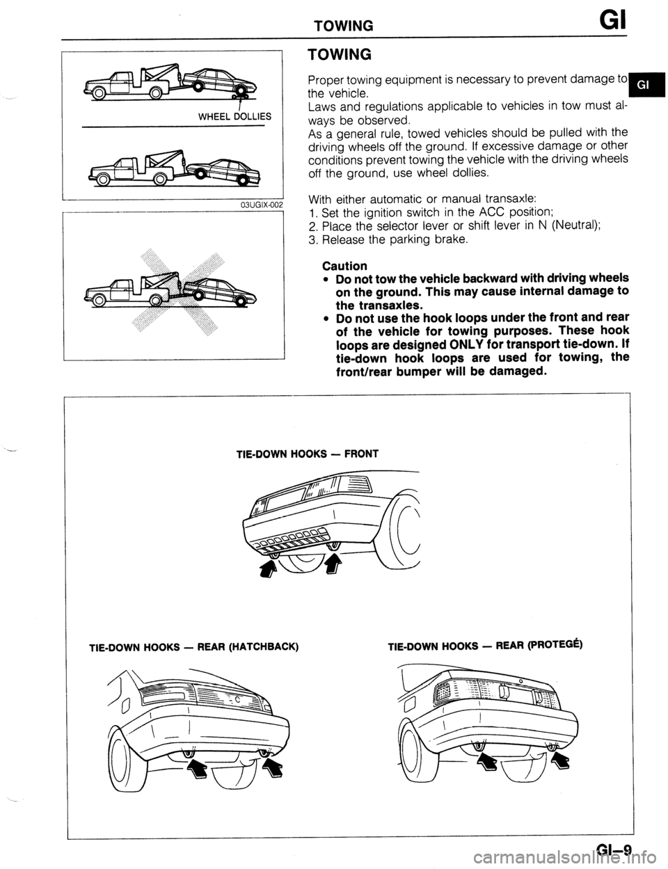
Proper towing equipment is necessary to prevent damage to
the vehicle.
Y
Laws and regulations applicable to vehicles in tow must al-
ways be observed.
As a general rule, towed vehicles should be pulled with the
driving wheels off the ground. If excessive damage or other
conditions prevent towing the vehicle with the driving wheels
off the ground, use wheel dollies.
With either automatic or manual transaxle:
1. Set the ignition switch in the ACC position;
2. Place the selector lever or shift lever in N (Neutral);
3. Release the parking brake.
Caution
l Do not tow the vehicle backward with driving wheels
on the ground. This may cause internal damage to
the transaxles.
l Do not use the hook loops under the front and rear
of the vehicle for towing purposes. These hook
loops are designed ONLY for transport tie-down. If
tie-down hook loops are used for towing, the
front/rear bumper will be damaged.
TIE-DOWN HOOKS - FRONT
TIE-DOWN HOOKS - REAR (HATCHBACK) TIE-DOWN HOOKS - REAR (PROTEGk)
GI-9
Page 54 of 1164
Bl ON-VEHICLE MAINTENANCE
01 EOBX-056
23UOBi -0:
Steps After Installation
1. Lower the vehicle.
2. Connect the negative battery cable.
3. Start the engine and check the ignition timing.
(Refer to page 61-8)
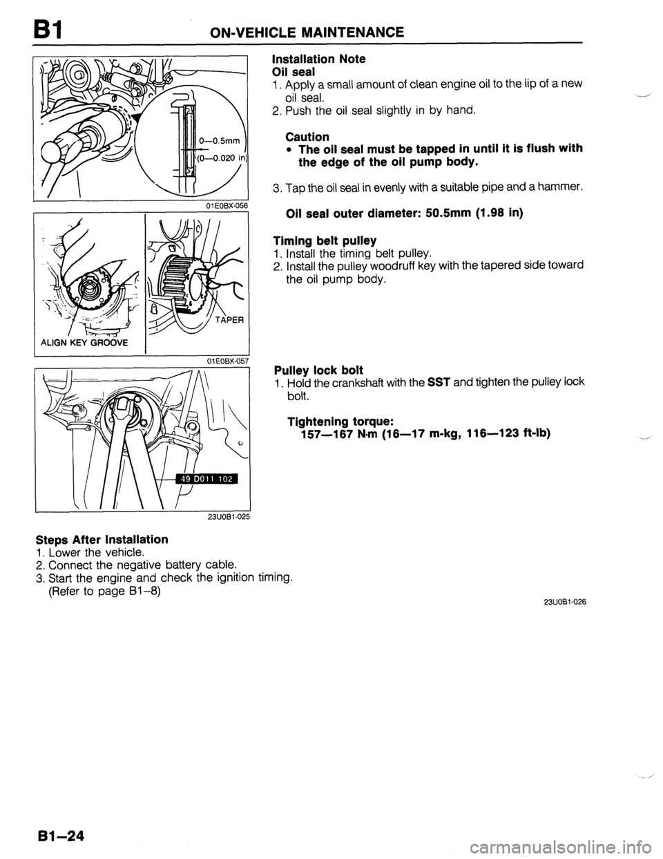
Installation Note
Oil seal
1. Apply a small amount of clean engine oil to the lip of a new
oil seal.
2. Push the oil seal slightly in by hand.
Caution
l The oil seal must be tapped in until it is flush with
the edge of the oil pump body.
3. Tap the oil seal in evenly with a suitable pipe and a hammer.
Oil seal outer diameter: 50.5mm (1.98 in)
Timing belt pulley
1. Install the timing belt pulley.
2. Install the pulley woodruff key with the tapered side toward
the oil pump body.
Pulley lock bolt
1. Hold the crankshaft with the SST and tighten the pulley lock
bolt.
Tightening torque:
157-167 N*rn (16-17 m-kg, 116-123 ft-lb)
23UOBi-026
Bl-24
Page 105 of 1164
ASSEMBLY Bl
OWOBX-20
23UOBl-049
5. Install the rear cover.
Tightening torque:
7.8-l 1 N*m (80-l 10 cm-kg, 89-95 in-lb)
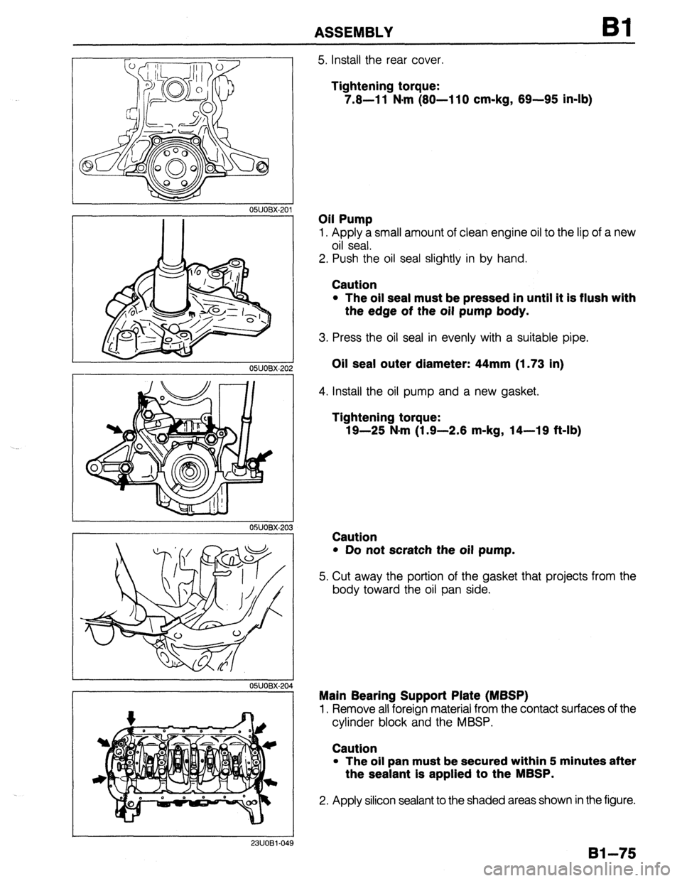
Oil Pump
1. Apply a small amount of clean engine oil to the lip of a new
oil seal.
2. Push the oil seal slightly in by hand.
Caution
l The oil seal must be pressed in until it is flush with
the edge of the oil pump body.
3. Press the oil seal in evenly with a suitable pipe.
Oil seal outer diameter: 44mm (1.73 in)
4. Install the oil pump and a new gasket.
Tightening torque:
19-25 N-m (1.9-2.8 m-kg, 14-19 ft-lb)
Caution
l Do not scratch the oil pump.
5. Cut away the portion of the gasket that projects from the
body toward the oil pan side.
Main Bearing Support Plate (MBSP)
1, Remove all foreign material from the contact surfaces of the
cylinder block and the MBSP.
Caution
l The oil pan must be secured within 5 minutes after
the sealant is applied to the MBSP.
2. Apply silicon sealant to the shaded areas shown in the figure.
81-75
Page 111 of 1164
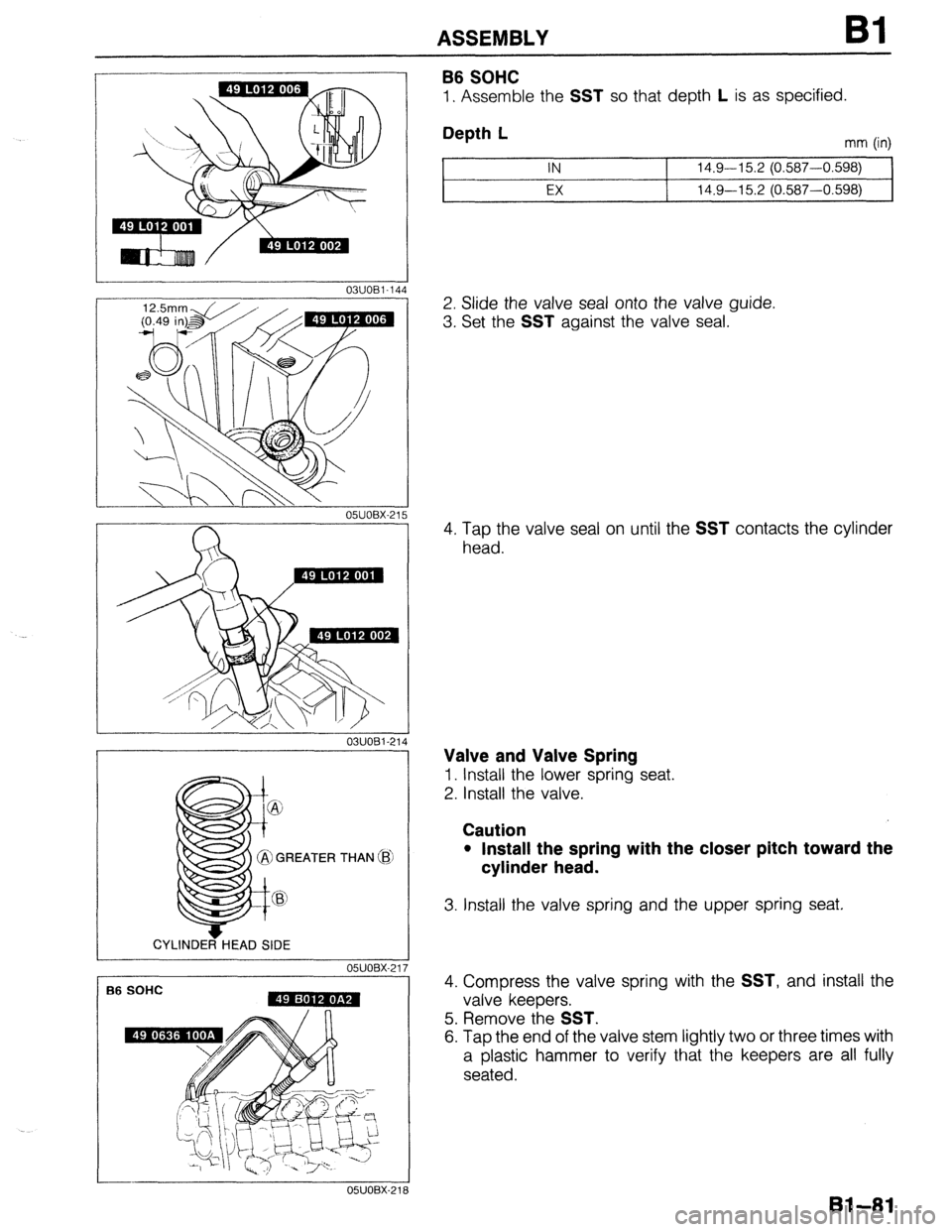
ASSEMBLY
03UOBi -144
03UOBl-214
GREATER THAN (i
CYLINDER HEAD SIDE
05UOBX-21
f36 SOHC
B6 SOHC
1. Assemble the SST so that depth L is as specified.
Depth L mm (in) 1 IN 14.9-15.2 (0.587-0.598)
EX 14.9-15.2 (0.587-0.598)
2. Slide the valve seal onto the valve guide.
3. Set the
SST against the valve seal.
4. Tap the valve seal on until the
SST contacts the cylinder
head.
Valve and Valve Spring
1. Install the lower spring seat.
2. Install the valve.
Caution
l Install the spring with the closer pitch toward the
cylinder head.
3. Install the valve spring and the upper spring seat.
4. Compress the valve spring with the
SST, and install the
valve keepers.
5. Remove the
SST.
6. Tap the end of the valve stem lightly two or three times with
a plastic hammer to verify that the keepers are all fully
seated.
131-81
Page 159 of 1164
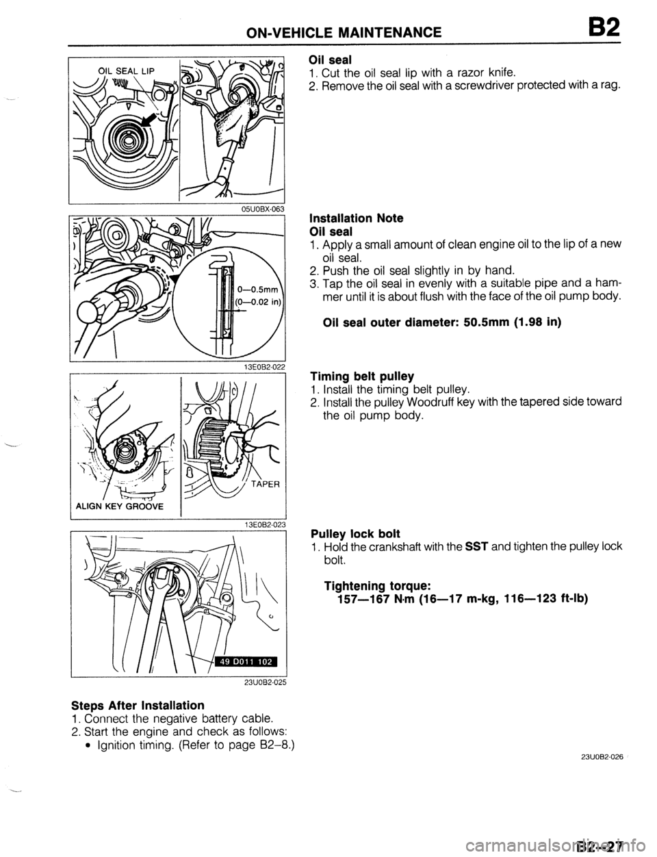
ON-VEHICLE MAINTENANCE
I 05UOBX-063
Oil seal
1. Cut the oil seal lip with a razor knife.
2. Remove the oil seal with a screwdriver protected with a rag.
13EOB2-02
ALIGN.KEY GRCi&E
13EOB2-02
23UOB2-025
Steps After Installation
1. Connect the negative battery cable.
2. Start the engine and check as follows:
l Ignition timing. (Refer to page 92-8.)
3
Installation Note
Oil seal
1. Apply a small amount of clean engine oil to the lip of a new
oil seal.
2. Push the oil seal slightly in by hand.
3. Tap the oil seal in evenly with a suitable pipe and a ham-
mer until it is about flush with the face of the oil pump body.
Oil seal outer diameter: 50.5mm (1.98 in)
Timing belt pulley
1. Install the timing belt pulley.
2. Install the pulley Woodruff key with the tapered side toward
the oil pump body.
Pulley lock bolt
1. Hold the crankshaft with the SST and tighten the pulley lock
bolt.
Tightening torque:
157-187 N.m (18-17 m-kg, 116-123 ft-lb)
23UOB2-026
82-27
Page 207 of 1164
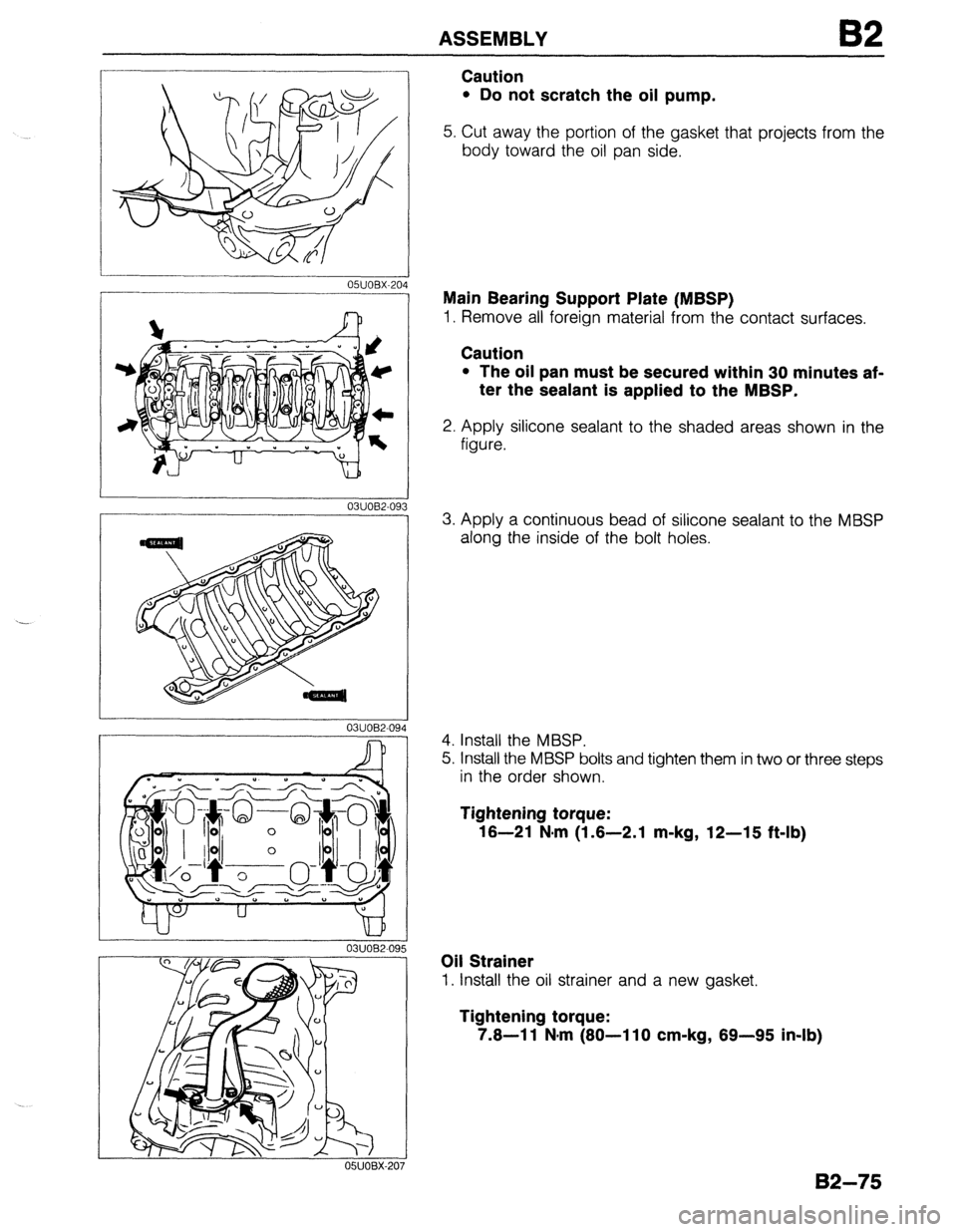
ASSEMBLY 82
03UOB2-09
03UOB2-094
-
Caution
l Do not scratch the oil pump.
5. Cut away the portion of the gasket that projects from the
body toward the oil pan side.
Main Bearing Support Plate (MBSP)
1. Remove all foreign material from the contact surfaces.
Caution
l The oil pan must be secured within 30 minutes af-
ter the sealant is applied to the MBSP.
2. Apply silicone sealant to the shaded areas shown in the
figure.
3. Apply a continuous bead of silicone sealant to the MBSP
along the inside of the bolt holes.
4. Install the MBSP.
5. Install the MBSP bolts and tighten them in two or three steps
in the order shown.
Tightening torque:
16-21 N,m (1.6-2.1 m-kg, 12-15 ft-lb)
Oil Strainer
1. Install the oil strainer and a new gasket.
Tightening torque:
7.6-l 1 N-m (80-l 10 cm-kg, 89-95 in-lb)
B2-75
Page 210 of 1164
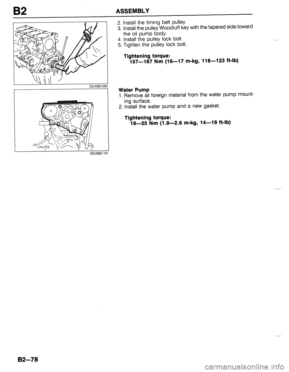
I32 ASSEMBLY
Qill’ ’ 23UOB2-050
03UOB2-10
2. Install the timing belt pulley.
3. install the pulley Woodruff key with the tapered side toward
the oil pump body.
4. Install the pulley lock bolt.
5. Tighten the pulley lock bolt.
Tightening torque:
157-167 N#rn (16-17 m-kg, 116-123 ft-lb)
Water Pump
1. Remove all foreign material from the water pump mount-
ing surface.
2. Install the water pump and a new gasket.
Tightening torque:
19-25 N.m (1.9-2.6 m-kg, 14-19 ft-lb)
82-78
Page 212 of 1164
62 ASSEMBLY
I OWOBX-21!
I CYLINDER HEAD SIDE
05UOBX-2
I
05UOBX-21 6
i
17
05UOBX-2
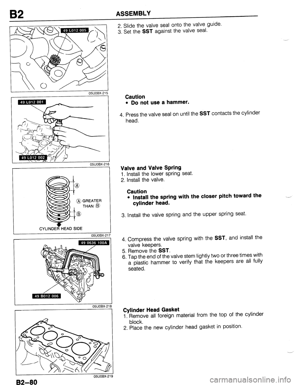
2. Slide the valve seal onto the valve guide.
3. Set the
SST against the valve seal.
Caution
l Do not use a hammer.
4. Press the valve seal on until the SST contacts the cylinder
head.
Valve and Valve Spring
1. Install the lower spring seat.
2. Install the valve.
Caution
l Install the spring with the closer pitch toward the
cylinder head. .---
3. Install the valve spring and the upper spring seat.
4. Compress the valve spring with the
SST, and install the
valve keepers.
5. Remove the
SST.
6. Tap the end of the valve stem lightly two or three times with
a plastic hammer to verify that the keepers are all fully
seated.
Cylinder Head Gasket
1. Remove all foreign material from the top of the cylinder
block.
2. Place the new cylinder head gasket in position.
82-80
Page 247 of 1164
OIL PUMP D
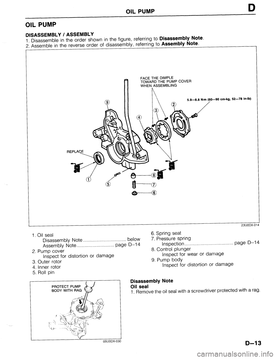
OIL PUMP
DISASSEMBLY / ASSEMBLY
1 Disassemble in the order shown in the figure, referring to Disassembly Note.
2: Assemble in the reverse order of disassembly, referring to Assembly Note.
FACE THE DIMPLE
TOWARD THE PUMP COVER
WHEN ASSEMBLING
O-90 cm-kg, 52-78 in-lb)
-8
23UODX-014
1. Oil seal
Disassembly Note . . . . . . . . . . . . . . . . . . . . . . . . . . . . . . . below
Assembly Note .,,..,.....,..,............ page D-14
2. Pump cover
Inspect for distortion or damage 6. Spring seat
7. Pressure spring
Inspection ..,..,.....,..,..,..,.............. page D-l 4
8. Control plunger
Inspect for wear or damage
9. Pump body
3. Outer rotor
4. Inner rotor
5. Roll pin
PROTECT PUMP
BODY WITH RAG
x9 05UODX-OC IO
Inspect for distortion or damage
Disassembly Note
Oil seal
1. Remove the oil seal with a screwdriver protected with a rag.
D-13