service MAZDA PROTEGE 1992 Workshop Manual
[x] Cancel search | Manufacturer: MAZDA, Model Year: 1992, Model line: PROTEGE, Model: MAZDA PROTEGE 1992Pages: 1164, PDF Size: 81.9 MB
Page 1 of 1164
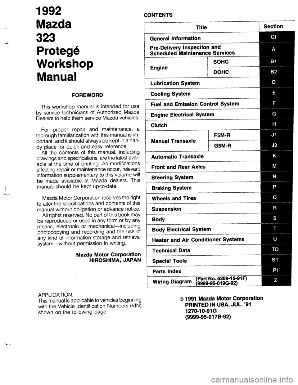
1992
Mazda
CONTENTS
Protege
Workshop
Manual
FOREWORD
This workshop manual is intended for use
by service technicians of Authorized Mazda
Dealers to help them service Mazda vehicles.
For proper repair and maintenance, a
thorough familiarization with this manual is im-
portant, and it should always be kept in a han-
dy place for quick and easy reference.
All the contents of this manual, including
drawings and specifications, are the latest avail-
able at the time of printing. As modifications
affecting repair or maintenance occur, relevant
information supplementary to this volume will
be made available at Mazda dealers. This
manual should be kept up-to-date.
Mazda Motor Corporation reserves the right
to alter the specifications and contents of this
manual without obligation or advance notice.
All rights reserved. No part of this book may
be reproduced or used in any form or by any
means, electronic or mechanical-including
photocopying and recording and the use of
any kind of information storage and retrieval
system-without permission in writing.
Mazda Motor Corporation
HIROSHIMA, JAPAN
APPLICATION:
This manual is applicable to vehicles beginning
with the Vehicle Identification Numbers (VIN)
shown on the following page.
Title
General Information Section
Pre-Delivery Inspection and
Scheduled Maintenance Services
SOHC
Engine
DOHC
Lubrication System
Cooling System
Fuel and Emission Control System
Engine Electrical System
Clutch
FSM-R
Manual Transaxle
GSM-R
Automatic Transaxle
Front and Rear Axles
Steering System
Braking System
Wheels and Tires
Suspension
Body
--
Body Electrical System
Heater and Air Conditioner Systems
Technical Data
Special Tools
Parts Index
Wiring DNvam
I Part No. 5209-10-91 F)
9999~95-019(3-92)
o 1991 Mazda Motor Corporation
PRINTED IN USA, JUL. ‘91
1270-l O-91 G
(9999-95-0178-92)
Page 4 of 1164
IMPORTANT INFORMATION
IMPORTANT INFORMATION
BASIC ASSUMPTIONS
This workshop manual assumes that you have certain special tools that are necessary for the safe and effi-
cient performance of service operations on Mazda vehicles and that you know how to use them properly.
It also assumes that you are familiar with automobile systems and basic service and repair procedures. You
should not attempt to use this manual unless these assumptions are correct and you understand the conse-
quences described below.
SAFETY RISK
This manual contains certain notes, warnings, and other precautionary information that you should carefully
read and follow to reduce the risk of personal injury to yourself or others and the risk of improper service
that may damage the vehicle or render it unsafe. If there is no such information in regard to any specific
service method, this does not mean there is no possibility that personal safety or vehicle safety will be
jeopardized by the use of incorrect methods or tools.
POSSIBLE LOSS OF WARRANTY
The manufacturer’s warranty on Mazda vehicles and engines can be voided if improper service or repairs
are performed by persons other than those at an Authorized Mazda Dealer.
WARNING ON LUBRICANTS AND GREASES
Avoid all prolonged and repeated contact with mineral oils, especially used oils. Used oils contaminated
during service (e.g., engine sump oils) are more irritating and more likely to cause serious effects, including
skin cancer, in the event of gross and prolonged skin contact.
Wash skin thoroughly after work involving oil.
Protective hand cleaners may be of value provided they can be removed from the skin with water. Do not
use gasoline, paraffin, or other solvents to remove oil from the skin.
Lubricants and greases may be slightly irritating to the eyes.
Repeated or prolonged skin contact should be avoided by wearing protective clothing if necessary. Particu-
lar care should be taken with used oils and greases containing lead. Do not allow work clothing to be con-
taminated with oil. Dry clean or launder such clothing at regular intervals.
9MUGIX-002
GI-2
Page 5 of 1164
HOW TO USE THIS MANUAL GI
HOW TO USE THIS MANUAL
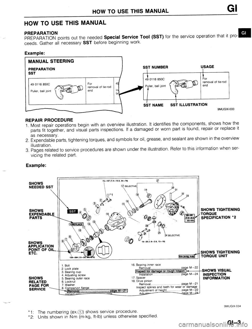
PREPARATION
PREPARATION points out the needed Special Service Tool (SST) for the service operation that it pro- m
ceeds. Gather all necessary
SST before beginning work.
Example:
49 0118 850C
removal of be-rod
9MUGIX-033
REPAIR PROCEDURE
1. Most repair operations begin with an overview illustration. It identifies the components, shows how the
parts fit together, and visual parts inspections. If a damaged or worn part is found, repair or replace it
as necessary.
2. Expendable parts, tightening torques, and symbols for oil, grease, and sealant are shown in the overview
illustration.
3. Pages related to service procedures are shown under the illustration. Refer to this information when ser-
vicing the related part.
Example:
SHOWS
NEEDED SST
SHOWS
APPLICATION
#T OF OIL,
SHOWS
RELATED
PAGE FOR
SERVICE ----
3. Bearing cup 1. Bolt
2. Lock Dlate
4. Adjusting screw
5. Bearing outer race
6. Locknut
7. Washer
8. Companion flange 16. Bearing Inner race
@ Removal. ,,,..,,,..
lnstallatlon page
page M--5 M-Z
i 7. Spacer
18. Drive pinion
Removal, .,,, ,.,, .,......... page M--i
Inspect spllnes and teeth for wear or damagl
Adjustment of height page M-2
Adurstp- w
SHOWS TIGHTENING
TORQUE
SPECIFICATION ‘2
SHOWS TIGHTENING
rORQlJE UNIT
SHOWS VISUAL
INSPECTION
INFORMATION
* 1: The numbering (ex.a) shows service procedure.
*2: Units shown in N.m (m-kg, ft-lb) unless otherwise specified.
9MUGIX-034
GI-3
Page 6 of 1164
HOW TO USE THIS MANUAL/FUNDAMENTAL PROCEDURES
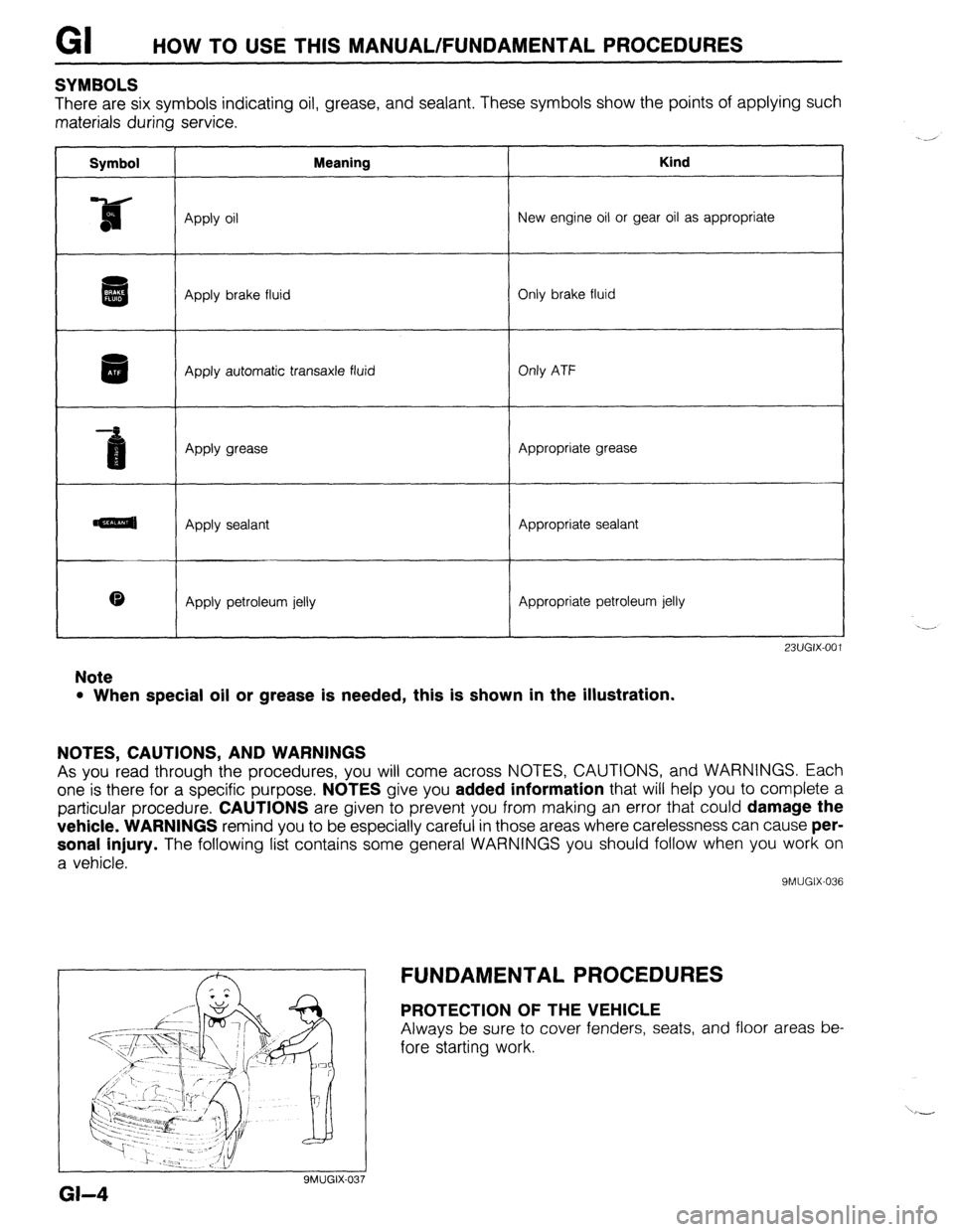
SYMBOLS
There are six symbols indicating oil, grease, and sealant. These symbols show the points of applying such
materials during service.
Symbol Meaning Kind
Apply oil New engine oil or gear oil as appropriate
aI i . Apply brake fluid Only brake fluid
Apply automatic transaxle fluid Only ATF
Apply grease Appropriate grease
amal Apply sealant Appropriate sealant
0 Apply petroleum jelly Appropriate petroleum jelly
23UGIX-001
Note
l When special oil or grease is needed, this is shown in the illustration.
NOTES, CAUTIONS, AND WARNINGS
As you read through the procedures, you will come across NOTES, CAUTIONS, and WARNINGS. Each
one is there for a specific purpose.
NOTES give you added information that will help you to complete a
particular procedure.
CAUTIONS are given to prevent you from making an error that could damage the
vehicle. WARNINGS
remind you to be especially careful in those areas where carelessness can cause per-
sonal injury.
The following list contains some general WARNINGS you should follow when you work on
a vehicle.
9MUGIX-036
SMUGIX-037
a-4 FUNDAMENTAL PROCEDURES
PROTECTION OF THE VEHICLE
Always be sure to cover fenders, seats, and floor areas be-
fore starting work.
Page 12 of 1164
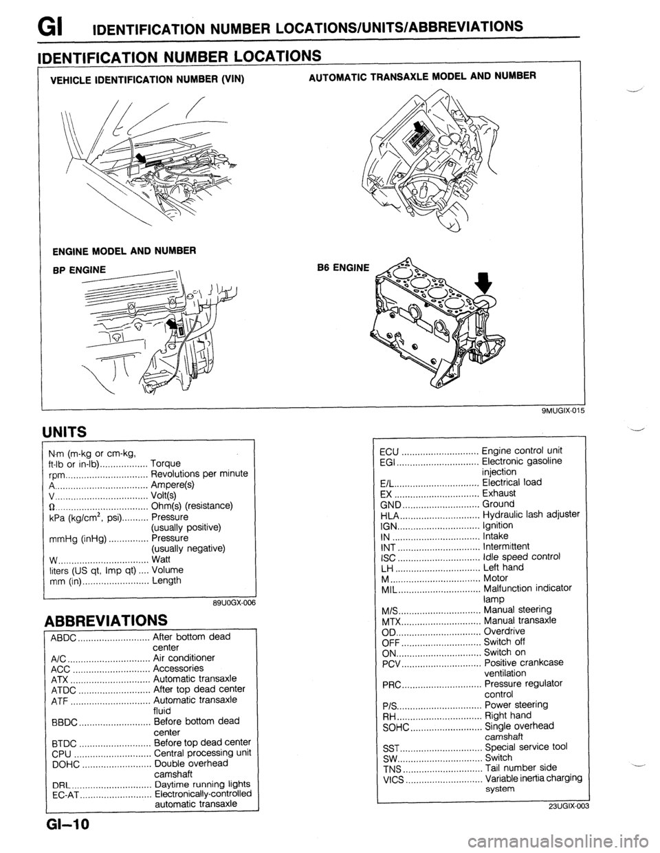
GI IDENTIFICATION NUMBER LOCATIONS/UNITS/ABBREVlATlONS
VEHICLE IDENTIFICATION NUMBER (VIN) AUTOMATIC TRANSAXLE MODEL AND NUMBER
ENGINE MODEL AND NUMBER
B6 ENGINE
IDENTIFICATION NUMBER LOCATIONS
UNITS
I
N.m (m-kg or cm-kg,
ft-lb or in-lb) . . . . . . . . . . . . . . . . . . Torque
rpm ._..,,,.............,.......... Revolutions per minute
A . . . . . . . . . . . . . . . . . Ampere(s)
v, . . . . . . . . . . . . . .
Volt(s)
$2 _....._..,......................... Ohm(s) (resistance)
kPa (kg/cm2,
psi) . . . . . . . . . . Pressure
(usually positive)
mmHg (inHg) . . . . . . . . . . . . . . . Pressure
(usually negative)
W.. . . . . . . . . . . .
Watt
liters (US qt, Imp qt) ,... Volume
mm (in) ..,......,...,........... Length
89UOGX-00
ABBREVIATIONS
ABDC . . . . . . . . . . . . . . . . . . . . .
After bottom dead
center
A/C . . . . . . . . . . . . . . . . . . . . . . . . . . . . . . .
Air conditioner
ACC ..,.,...... 3 . . . . . . . . . . . . . . . . . Accessories
ATX . . . . . . . . . . . . . . . . . . . . . . . . . . . . . . Automatic transaxle
ATDC ..,,...,...,............... After top dead center
ATF . . . . . . . . . . . . . . . . . Automatic transaxle
fluid
BBDC ,,..,.......,...,......,... Before bottom dead
center
BTDC .,......,...............,.. Before top dead center
CPU ..,,.......,...,..........,.. Central processing unit
DOHC ..,...,..,............,,.. Double overhead
camshaft
DRL ____.......................... Daytime running lights
EC-AT .,_.......,............,,.. Electronically-controlled
automatic transaxle
L
GI-10
ECU ............................. Engine control unit
EGI ............................... Electronic gasoline
injection
E/L.. .............................. Electrical load
EX ................................ Exhaust
GND.. ........................... Ground
HLA.. ............................ Hydraulic lash adjuster
IGN ............................... Ignition
IN ................................. Intake
INT ............................... Intermittent
ISC
............................... idle speed control
LH ................................ Left hand
M..
................................ Motor
MIL..
............................. Malfunction indicator
lamp
M/S..
............................. Manual steering
MTX.. ............................ Manual transaxle
OD ................................ Overdrive
OFF.. ............................ Switch off
ON.. .............................. Switch on
PCV.. ............................ Positive crankcase
ventilation
PRC..
............................ Pressure regulator
control
PIS ................................ Power steering
RH..
.............................. Right hand
SOHC.. .........................
z;;kiprhead
SST ............................... Special service tool
SW.. .............................. Switch
TNS
.............................. Tail number side
VICS
............................. Variable inertia charging
system
23UGIX-00
Page 14 of 1164
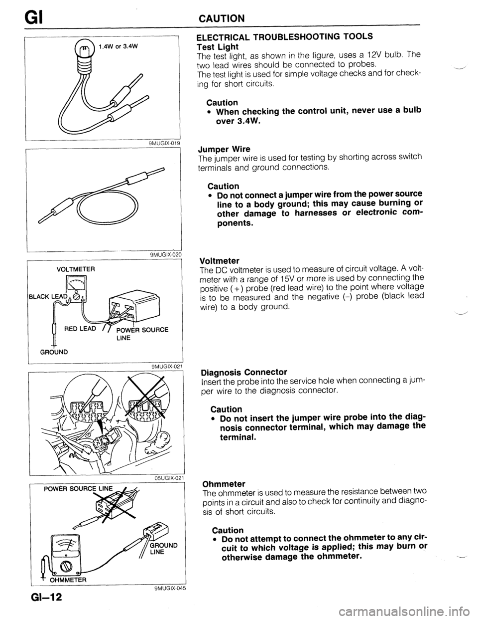
GI CAUTION
1.4W or 3.4W
9MUGIX-019 ELECTRICAL TROUBLESHOOTING TOOLS
Test Light
The test light, as shown in the figure, uses a 12V bulb. The
two lead wires should be connected to probes.
The test light is used for simple voltage checks and for check-
ing for short circuits.
Caution
l When checking the control unit, never use a bulb
over 3.4W.
SMUGIX-621
VOLTMETER
BLACK
/ GR&ND
9MUGIX-021
05UGIX-021
YMUGIX-04
Jumper Wire
The jumper wire is used for testing by shorting across switch
terminals and ground connections.
Caution
l Do not connect a jumper wire from the power source
line to a body ground; this may cause burning or
other damage to harnesses or electronic com-
ponents.
Voltmeter
The DC voltmeter is used to measure of circuit voltage. A volt-
meter with a range of 15V or more is used by connecting the
positive (-t-) probe (red lead wire) to the point where voltage
is to be measured and the negative (-) probe (black lead
wire) to a body ground.
-,’
Diagnosis Connector
Insert the probe into the service hole when connecting a jum-
per wire to the diagnosis connector.
Caution
. Do not insert the jumper wire probe into the diag-
nosis connector terminal, which may damage the
terminal.
Ohmmeter
The ohmmeter is used to measure the resistance between two
points in a circuit and also to check for continuity and diagno-
sis of short circuits.
Caution
l Do not attempt to connect the ohmmeter to any cir-
cuit to which voltage is applied; this may burn or
otherwise damage the ohmmeter.
GI-12
Page 19 of 1164
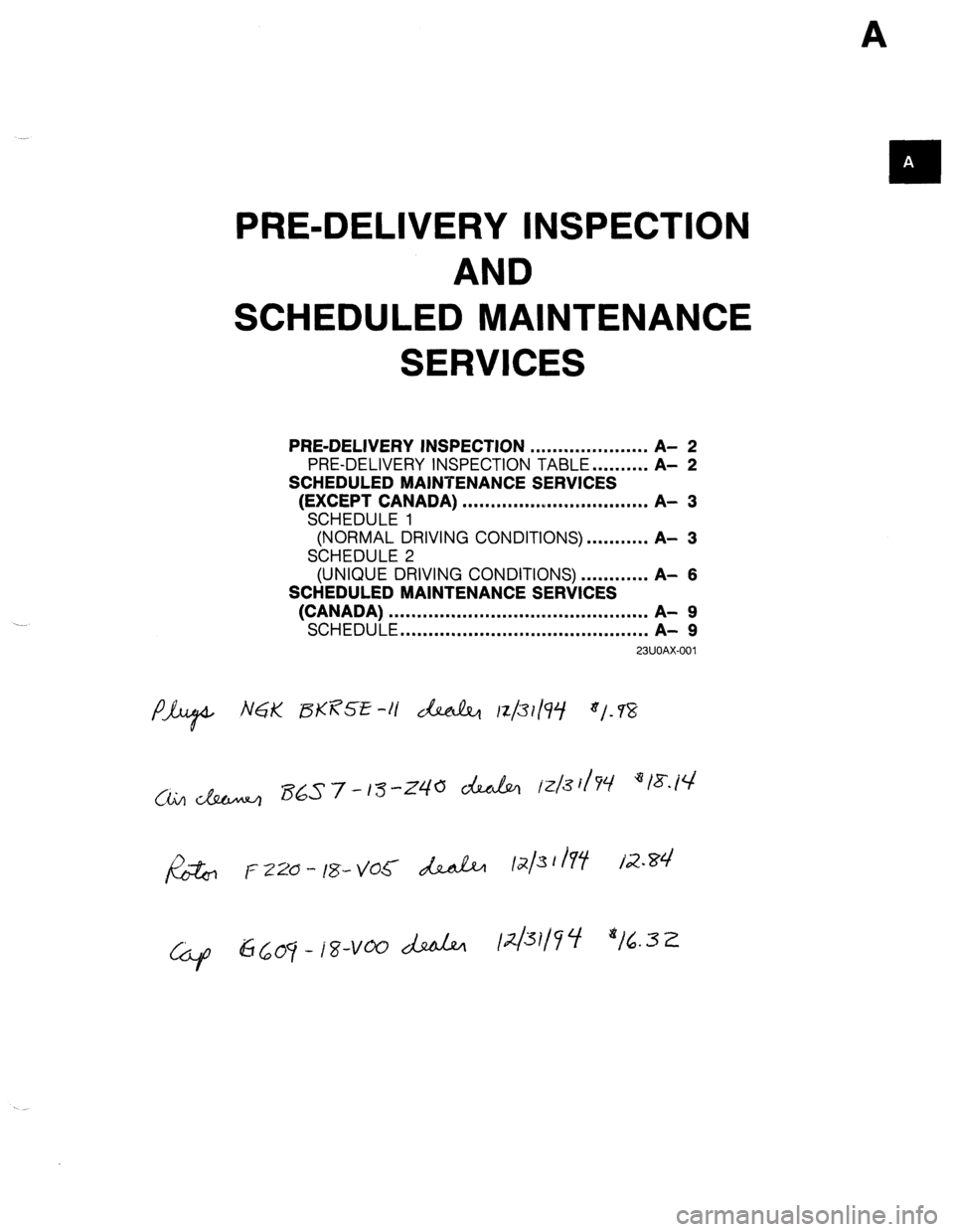
A
PRE-DELIVERY INSPECTION
AND
SCHEDULED MAINTENANCE
SERVICES
PRE-DELIVERY
INSPECTION
. . . . . . . . . . . . . . . . . . . . . A- 2
PRE-DELIVERY INSPECTION TABLE . . . . . . . . . . A-
2
SCHEDULED MAINTENANCE SERVICES
(EXCEPT CANADA)
. . . . . . . . . . . . ..I..................
A- 3
SCHEDULE 1
(NORMAL DRIVING CONDITIONS) . . . . . . . . . ,. A-
3
SCHEDULE 2
(UNIQUE DRIVING CONDITIONS) . . . . . . . . . . . . A-
6
SCHEDULED MAINTENANCE SERVICES
(CANADA)
. . . . . . . . . . . . . . . . . . . . . . . . . . . . . . . . . . . . . . ...‘....
A- 9
SCHEDULE
. . . . . . . . . . . . . . . . . . . . . . . . . . . . . . . . . . . . . . ...*..
A- 9
23UOAX-001
Page 21 of 1164
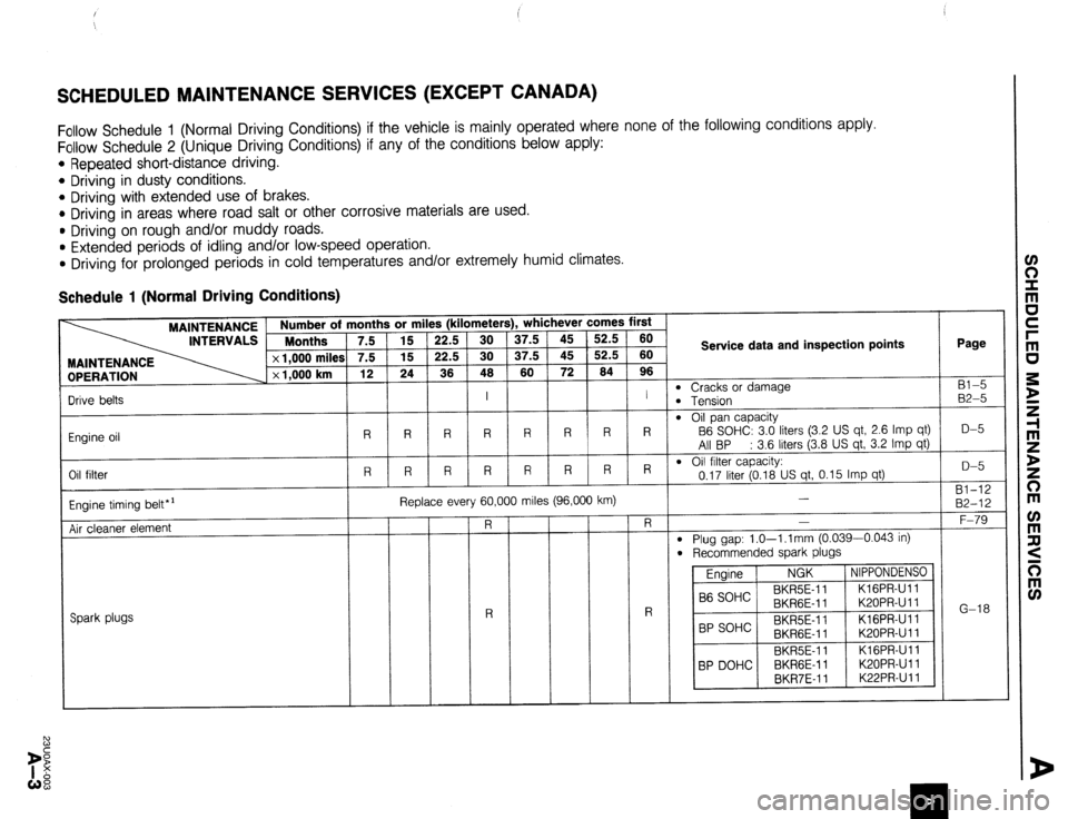
SCHEDULED MAINTENANCE SERVICES (EXCEPT CANADA)
Follow Schedule 1 (Normal Driving Conditions) if the vehicle is mainly operated where none of the following conditions apply.
Follow Schedule 2 (Unique Driving Conditions) if any of the conditions below apply:
l Repeated short-distance driving.
l Driving in dusty conditions.
* Driving with extended use of brakes.
* Driving in areas where road salt or other corrosive materials are used.
l Driving on rough and/or muddy roads.
l Extended periods of idling and/or low-speed operation.
l Driving for prolonged periods in cold temperatures and/or extremely humid climates.
Schedule 1 (Normal Driving Conditions)
Number of months or miles (kilometers), whichever comes first
Months 7.5 15 22.5 30 37.5 45 52.5 60
7.5 15 22.5 30 37.5 45 52.5 60
12 24 36 46 60 72 64 96 Service data and inspection points Page
Bl-5
B2-5
D-5
D-5
Bl-12
B2-12
F-79
G-18 MAINTENANCE
OPERATION
m Cracks or damage
B Tension
m Oil pan capacity
B6 SOHC: 3.0 liters (3.2 US qt, 2.6 Imp qt)
All BP : 3.6 liters (3.8 US qt, 3.2 Imp qt)
l Oil filter capacity:
0.17 liter (0.18 US qt, 0.15 Imp qt)
-
l Plug gap: 1.0-l .l mm (0.039-0.043 in)
l Recommended spark plugs
Engine NGK NIPPONDENSO
B6 SOHC BKR5E-11 KIGPR-Ull
BKRGE-11 K20PR-U 11
BP SOHC BKR5E-11 KlGPR-Ull
BKRGE-11 K20PR-U 11
BKR5E-11 KlGPR-Ull
BP DOHC BKRGE-11 K20PR-U 11
BKR7E-11 K22PR-Ull I I
R R R R R R R R
R R R R R R R R Drive belts
Engine oil
Oil filter
Engine timing belt*’
Air cleaner element Replace every 60,000 miles (96,000 km)
I
Spark plugs
Page 22 of 1164
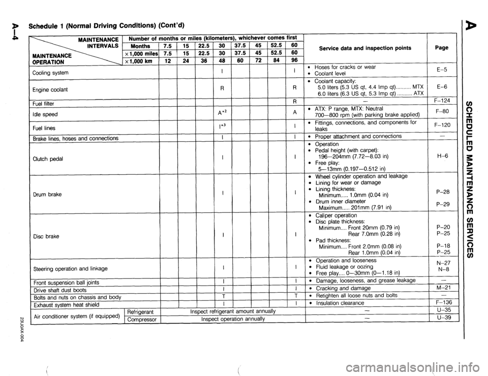
7 Schedule 1 (Normal Driving Conditions) (Cont’d)
MAINTENANCE
INTERVALS 1 ::::“’ rths ’ 7.5
DPERATION x 1,000 miles
x 1,000 km 3r mi
15
15
24
1
Page
l- . whichever comes first s (kilometer!
37.5
37.5
60 52.5
52.5
64 60
60
96
I
l-7
Service data and inspection points
l Hoses for cracks or wear l Coolant level E-5
Zooling system
Engine coolant
Fuel filter
‘die speed
Fuel lines
Brake lines, hoses and connections
l Coolant capacity:
5.0 liters (5.3 US qt, 4.4 Imp qt) . . . . . . . . . . MTX
6.0 liters (6.3 US qt, 5.3 Imp qt) . . . . . . . . . . ATX
I E-6 -
F-l 24
l ATX: P range, MTX: Neutral
700-800 rpm (with parking brake applied)
l Fittings, connections, and components for F-80
F-120
-
H-6
P-28
P-29
P-20
P-25
P-18
P-25
---
N-27
N-8
-
M-21
-
F-136
u-35
u-39 leaks
0 Proper attachment and connections
l Operation l Pedal height (with carpet):
196-204mm (7.72-8.03 in)
l Free play:
5--13mm 10.197-0.512 in) Clutch pedal
l Wheel cylinder operation and leakage
l Lining for wear or damage l Lining thickness:
Minimum . . . . . 1 .Omm (0.04 in)
l Drum inner diameter
Maximum..... 201mm (7.91 in) Drum brake
l Caliper operation l Disc plate thickness:
Minimum.... Front 20mm (0.79 in)
Rear 7.0mm (0.28 in)
l Pad thickness:
Minimum.... Front 2.0mm (0.08 in)
Rear l.Omm (0.04 in)
l Operation and looseness l Fluid leakage or oozing l Free play.... O-30mm (O-l .18 in)
l Damage, looseness, and grease leakage
l Cracking and damage
l Retighten all loose nuts and bolts I
1
Disc brake
I
---l-T
Steering operation and linkage
Front suspension ball joints
Drive shaft dust boots
Bolts and nuts on chassis and body
Exhaust system heat shield
Air conditioner system (if equipped) Refrigerant
Compressor am01 anni I
l Insulation clearance
- ,.
Inspect rerrlgerar
Inspect operation annually -
Page 24 of 1164
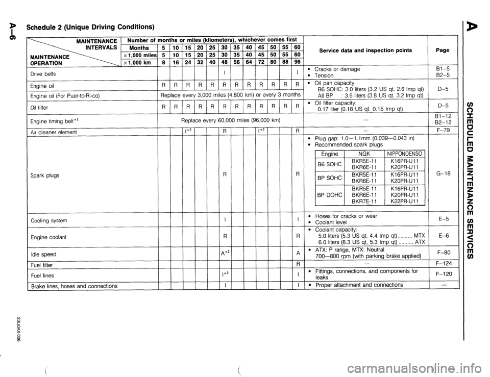
y Schedule 2 (Unique Driving Conditions)
OPERATION
Drive belts MAINTENANCE / Number of months or miles (kilometers), whichever comes first
INTERVALS Months
5 IO 15 20 25 30 35 40 45 50 55 60
x 1,000 milea i 5 10 15 20 25 30 35 40 45 50 55 60
x 1,000 km 8 16 24 32 40 48 56 64 72
80 88 96
I I Service data and inspection points Page
l Cracks or damage Bl-5 l Tension B2-5
l Oil pan capacity
B6 SOHC: 3.0 liters (3.2 US qt, 2.6 Imp qt)
All BP : 3.6 liters (3.8 US qt, 3.2 Imp qt)
l Oil filter capacity: D-5
I I I I I I I I I I I
RRRRRRR R R R R R
Replace every 3,000 miles (4,800 km) or every 3 months
R R R R R RRRRRRR
0.17 liter (0.18 US qt, 0.15 Imp qt) Engine oil
Engine oil (For Puer-to-Rico)
Oil filter D-5
81-12
82-12
F-79
G-18 Replace every 60,000 miles (96,000 km)
Engine timing belt*’
Air cleaner element -
-
-
-
-
-
-
-
- -
-
-
-
-
-
-
-
-
FL
-
R
-
I
-
R
-
4 *;
-
-
*3
T
- -
-
-
-
-
-
-
-
- -
-
-
-
-
-
-
-
-
*2 -
-
-
-
-
-
-
-
- - R -
l Plug gap: l.O--l.lmm (0.039-0.043 in)
l Recommended spark plugs
Engine NGK NIPPONDENSO
B6 SOHC BKR5E-11
KlGPR-Ull
BKRGE-I 1 K20PR-U 11
BP SOHC BKR5E-I 1 KlGPR-Ull
BKRGE-11 K20PR-U 11
BKRSE-I 1 Kl GPR-Ul 1
BP DOHC BKRGE-11 K20PRUll
BKR7E-11 K22PR-U 11 R
Spark plugs
I
l Hoses for cracks or wear l Coolant level E-5
Cooling system
R
l Coolant capacity:
5.0 liters (5.3 US qt, 4.4 Imp qt) MTX
6.0 liters (6.3 US qt, 5.3 Imp qt) ...,,,,,. ATX
l ATX: P range, MTX: Neutral E-6
Engine coolant
A
-
R
-
I
-
I Idle speed , F-80
F-124 / 700-800 rbrn (with parkina brake applied) -
- -
- , , I .I
-
Fuel filter
l Fittings, connections, and components for
leaks
l Prooer attachment and connections F-120
- Fuel lines
Brake lines. hoses and connections