oil MAZDA PROTEGE 1992 Workshop Manual
[x] Cancel search | Manufacturer: MAZDA, Model Year: 1992, Model line: PROTEGE, Model: MAZDA PROTEGE 1992Pages: 1164, PDF Size: 81.9 MB
Page 464 of 1164

G STARTING SYSTEM
STARTING SYSTEM
PREPARATION
SST
49 E301 144
Removing plate
I I 03UOGX-062
CIRCUIT DIAGRAM
I --II /l--f--I1 I It------t--r/
INHIBITER SWITCH-ATX 1 It---f-l/
SWITCH STARTER IF
SWFCH-MTX
II
BATTERY V 0
FIELD COIL
BRUSH
S TERMIN
M TERMINAL
““““.“I “1 Note
l BP ATX vehicles use a coaxial reduction starter.
G-24
Page 467 of 1164

STARTING SYSTEM G
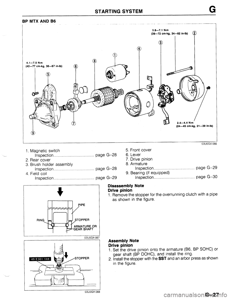
BP MTX AND B6
3.6-7.1 N.m
(39-72 cm-kg, 34-62 in-lb)
4.1-7.5 N.m
(42-77 cm-kg, 36-67 in-lb)
@
0
2.4-4.4 N.m
(24-45 cm-kg, 21-39 in-lb)
1. Magnetic switch 5. Front cover
Inspection . . . . . . . . . . . . . . . . . . . . . . . . . . . . . . . . . . . page G-28
6. Lever
2. Rear cover 7. Drive pinion
3. Brush holder assembly 8. Armature
Inspection.. .,..,........................... page G-28 Inspection .,,..,...............,.,........... page G-29
4. Field coil 9. Bearing (if equipped)
Inspection . . . . . . . . . . . . . . . . . . . . . . . . . . . . . . . . . . . page G-29 Inspection.. ,....,......................,... page G-30
--_I__-
03UOGX-06
03UOGX-06
Disassembly Note
Drive pinion
1. Remove the stopper for the overrunning clutch with a pipe
as shown in the figure.
Assembly Note
Drive pinion
1. Set the drive pinion onto the armature (66, BP SOHC) or
gear shaft (BP DOHC), and install the ring.
2. Install the stopper with the
SST and an arbor press as shown
in the figure.
G-27
Page 469 of 1164

STARTING SYSTEM G
WEAR LIMIT
/ -- _._- .------
03UOGX-07L i
-----.
i
03UOGX 076
03UOGX-07
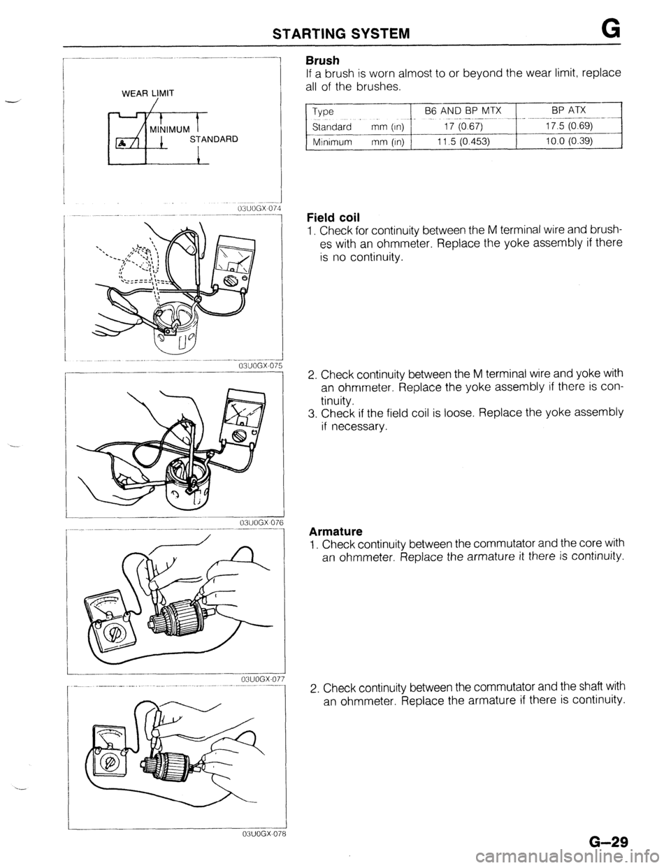
Brush
If a brush is worn almost to or beyond the wear limit, replace
all of the brushes.
Type
--pFeE?~Ix _~~_ -.~+~~zE~~:
Standard - mm (In) 1
--.-
Minimum mm (In) 11.5 (0.453) 10.0 (0.39)
Field coil
1. Check for continuity between the M terminal wire and brush-
es with an ohmmeter. Replace the yoke assembly if there
is no continuity.
2. Check continuity between the M terminal wire and yoke with
an ohmmeter. Replace the yoke assembly if there is con-
tinuity.
3. Check if the field coil is loose. Replace the yoke assembly
if necessary.
Armature
1. Check continuity between the commutator and the core with
an ohmmeter. Replace the armature it there is continuity.
2. Check continuity between the commutator and the shaft with
an ohmmeter. Replace the armature if there is continuity.
G-29
Page 475 of 1164

OUTLINE, TROUBLESHOOTING GUIDE
OUTLINE
SPECIFICATIONS
-
-
Item
Clutch control Engine/Transaxle B6 SOHC BP SOHC BP DOHC
F!Wl-R GBM-R Hvdraulic
Clutch cover
Clutch disc Type
Set load Diaphragm spring
N
(kg, lb) 1 3,630 (370, 814) 1 3,826 (390, 858) 1 3,846 (392, 862)
30 17.48)
200 (7.87) 215 (8.46) Outer diameter mm (in)
Inner diameter mm (in)
Pressure plate
side mm (in)
Thickness
Flywheel side
mm lit-d
1! , I
130 (5.12) ’ ’
150 i5.91 j
3.5 (0.138) 3.8 (0.150)
3.5 (0.138)
Type Suspended
Clutch pedal
Master cylinder
Release cylinder
Clutch fluid Pedal ratio 6.55
Full stroke mm (in) 135 (5.32)
Height (With carpet)
mm (in) 196-204 (7.72-8.03)
Inner diameter mm (in) 15.87 (0.625)
Inner diameter
mm (in) 19.05 (0.750)
SAE J1703 or FMVSS116 DOT-3
23UOHX-003
TROUBLESHOOTING GUIDE Problem Possible Cause Remedy Page
Slipping
Clutch disc facing worn excessively Replace H-15, 17
Clutch disc facing surface hardened or oil on surface Repair or replace H-15
Pressure plate damaged Repair or replace H-15
Diaphragm spring damaged or weakened Replace H-15
Insufficient clutch pedal play Adjust H- 5
Clutch pedal sticking Repair or replace H- 6
Flywheel damaged Repair or replace H-15, 17 Faulty disen-
Excessive runout or damaged clutch disc Replace H-15, 17 gagement Clutch disc splines rusted or worn Remove rust or replace H-15
Oil on facing Repair or replace H-15
Diaphragm spring weakened Replace H-15
Excessive clutch pedal play Adjust H- 5
Insufficient clutch fluid
Add fluid H- 3
Leakage of clutch fluid Locate and repair or -
replace Clutch vibrates
Oil on facing Repair or replace H-15 when accelerating Torsion rubbers weakened Replace H-15
Clutch disc facing hardened or damaged Repair or replace H-15
Clutch disc facing rivets loose Replace H-15
Pressure plate damaged or excessive runout Replace H-15
Flywheel surface hardened or damaged Repair or replace H-15
Loose or worn engine mount Tighten or replace - Clutch pedal
Pedal shaft not properly lubricated Lubricate or replace H- 6 sticking
Abnormal noise
Clutch release bearing damaged Replace H-15, 17
Poor lubrication of release bearing sleeve Lubricate or replace H-15
Torsion rubbers weakened Replace H-15
Excessive crankshaft end play Repair Refer to Section E
Pilot bearing worn or damaged Replace H-15, 18
Worn pivot points of release fork Repair or replace H-15
^^. .^. I~, ^r
H-3
Page 488 of 1164

H CLUTCH UNIT
/ 6fs 23UOHX-015
Removal Note
Clutch cover and disc
1. Install the SST or equivalent.
2. Loosen each bolt one turn at a time in a crisscross pattern
until spring tension is released. Then remove the clutch COV-
er and disc.
‘6
I
23UOHX-016
23UOHX-01
Pilot bearing
1. Remove the pilot bearing with the SST if necessary.
Flywheel
Note
l After removing the flywheel, inspect for oil leakage
past the crankshaft rear oil seal.
If necessary, replace the oil seal.
(Refer to Section B.) -J
1. Hold the flywheel with the SST or equivalent.
2. Remove the flywheel.
Installation Note
Flywheel
1. Wipe the bolts clean and apply sealant to the bolt threads.
2. Install the flywheel and the
SST or equivalent.
3. Tighten the bolts in the pattern shown.
Tightening torque:
96-103 N,m (9.6-10.5 m-kg, 71-76 ft-lb)
Pilot bearing
Note
l Install the pilot bearing flush with the flywheel.
1. Install the new bearing with a suitable pipe.
Bearing outer diameter: 35mm (1.376 in) .-’
Page 489 of 1164

CLUTCH UNIT, RELEASE BEARING, CLUTCH COVER, CLUTCH DISC H
L
13UOHX-01;
03UOHX-03 8
23UOHX-018
5
03UOHX-032
03UOHX-03
Clutch disc
1. Clean the clutch disc splines and main drive gear splines;
then apply organic molybdenum sulfide grease.
2. Hold the clutch disc in position with the
SST.
Clutch cover
1. Install the SST or equivalent.
2. Align the dowel holes with the flywheel dowels.
3. Tighten the bolts evenly and gradually in the pattern shown.
Tightening torque:
18-26 Nom (1.8-2.7 m-kg, 13-20 ft-lb)
RELEASE BEARING
INSPECTION
Note
l The clutch release bearing Is a sealed bearlng and
must not be washed in solvent.
1. Turn the bearing while applying force in the axial direction.
If the bearing sticks or has excessive resistance, replace it.
CLUTCH COVER
INSPECTION
Note
l Minor scoring or burning should be removed with
emery paper.
1. Inspect the contact surface of the clutch disc for scoring,
cracks, and burning. Repair or replace as necessary.
2. Inspect the contact surface of the clutch release bearing
for wear and cracks.
If there is wear or cracks, replace the clutch cover.
CLUTCH DISC
INSPECTION
Note
l Use sandpaper if the trouble is minor.
1. Inspect the lining surface for burning and oil contamination.
Replace the clutch disc if it is badly burned or oil soaked.
2. Inspect for loose facing rivets and rubbers.
Replace the clutch disc if either is loose.
H-17
Page 491 of 1164

Jl
MANUAL TRANSAXLE
(F5M-R)
INDEX ..................................................... Jl- 2
OUTLINE ................................................ Jl- 3
SPECIFICATIONS ................................... Jl- 3
STRUCTURAL VIEW ............................... Jl- 4
POWER FLOW ...................................... Jl- 5
TROUBLESHOOTING GUIDE.. ................... Jl- 6
TRANSAXLE OIL ..................................... Jl- 7
INSPECTION ......................................... Jl- 7
REPLACEMENT ..................................... Jl- 7
TRANSAXLE ........................................... Jl- 6
PREPARATION ...................................... Jl- 6
REMOVAL ............................................ 51-10
DISASSEMBLY ...................................... Jl-14
INSPECTION ......................................... 51-27
ASSEMBLY ........................................... Jl-30
INSTALLATION ...................................... Jl-46
DIFFERENTIAL ........................................ Jl-52
PREPARATION ...................................... 51-52
DISASSEMBLY I INSPECTION / ASSEMBLY Jl-53
SHIFT MECHANISM ................................. Jl-56
OVERHAUL .......................................... Jl-56
OWOJl-001
Page 492 of 1164

Jl INDEX
INDEX
BACK-UP LdHT SWITCH
SERVICE, SECTION T VISCOSITY: SAE 75W-90
CAPACITY : 2.68 liters (2.83 US qt, 2.36 Imp qt)
03UOJl-00
1, Transaxle 2. Differential
Removal.. ..................................
page Jl-IO Disassembly I Inspection I
Disassembly ................................ .............................. page Jl-14 Assembly page Jl-53
Inspection ..................................
page J 1-27 3. Shift mechanism
Assembly .................................. page J l-30 Overhaul ...................................
page Jl-56
Installation ................................. page Jl -48 4. Transaxle oil
Inspection. .................................
page Jl- 7
Replacement ............................. page Jl- 7
Page 493 of 1164

OUTLINE Jl
OUTLINE
SPECIFICATIONS
c EnginelTransaxle
B6 SOHC BP SOHC
Item FSM-R
I
Transaxle control
I Floor shift
Synchromesh system Forward: Synchromesh
Reverse: Selective sliding
1 1st
I 3.416
2nd 1.842
I
Gear ratio
4th
Final aear ratio 5th
Reverse I
0.918
0.731
3.214
4.105 3.619
Grade
I API service GL-4
Oil Viscosity
I SAE 75W-90
Capacity liters (US qt, Imp qt) 2.68 (2.83, 2.36)
13UOJl-00
Jl-3
Page 496 of 1164

Jl TROUBLESHOOTING GUIDE
TROUBLESHOOTING GUIDE
Problem
Shift lever won’t shift
smoothly or is hard
to shift
Too much play in
shift lever
I------
Difficult to shift
Won’t stay in gear
Abnormal noise
I
Possible cause
Seized shift lever ball
Seized change control rod joint
Bent change control rod
Worn change control rod bushing
Weak shift lever ball spring
Worn shift lever ball bushing
Bent change rod
No grease in transaxle control
Insufficient oil
Deterioration of oil quality
Wear or play of shift fork or shift rod
Worn synchronizer ring
Worn synchronizer cone of gear
Bad contact of synchronizer ring and cone of gear
Excessive longitudinal play of gears
Worn bearing
Worn synchronizer key spring
Excessive primary shaft gear bearing preload
improperly adjusted change guide plate
Bent change control rod
Worn change control rod bushing
Weak shift lever ball spring
improperly installed extension bar
Worn shift fork
Worn clutch hub
Worn clutch hub sleeve
Worn gear sliding part of both shaft gears
Worn gear sliding part of each gear
Worn steel sliding groove of control end
Weak spring pressing against steel ball
Excessive thrust clearance
Worn bearing
Improperly installed engine mount
Insufficient oil
Deterioration of oil quality
Worn bearing
Worn sliding surfaces of gears or shafts
Excessive gear backlash
Damaged gear teeth
Foreign material in gears
Damaged differential gear or excessive backlash Remedy Replace
Replace
Replace
Replace
Replace
Replace
Replace
Lubricate with grease
Add oil
Replace with oil of
specified quality
Replace
Replace
Replace
Replace
Replace
Replace
Replace
Adjust
Adjust
Replace
Replace
Replace
Tighten
Replace
Replace
Replace
Replace
Replace
Replace
Replace
Replace
Replace
Tighten
Add oil
Replace
Adjust or replace
Replace
Replace
Replace with oil of
specified quality
Replace
Adjust or replace Page Jl-56
Jl-56
Jl-56
Jl-56
Jl-56
Jl-56
Jl-56
Jl-56
Jl- 7
Jl- 7
Jl-14
Jl-22, 24
Jl-22, 24
Jl-22, 24
Jl-22, 24
Jl-22, 24
Jl-22, 24
Jl-36
Jl-17
Jl-56
Jl-56
Jl-56
Jl-56
Jl-14
Jl-22, 24
Jl-22, 24
Jl-22, 24
Jl-22, 24
Jl-14
Jl-14
Jl-22, 24
Jl-22, 24
Jl-48
Jl- 7
Jl- 7
Jl-22, 24
Jl-22, 24
Jl-22, 24
Jl-22, 24
Jl-22, 24
Jl-53
03UOJl-OC --
-../
51-6