oil MAZDA PROTEGE 1992 Workshop Manual
[x] Cancel search | Manufacturer: MAZDA, Model Year: 1992, Model line: PROTEGE, Model: MAZDA PROTEGE 1992Pages: 1164, PDF Size: 81.9 MB
Page 245 of 1164
OIL PAN
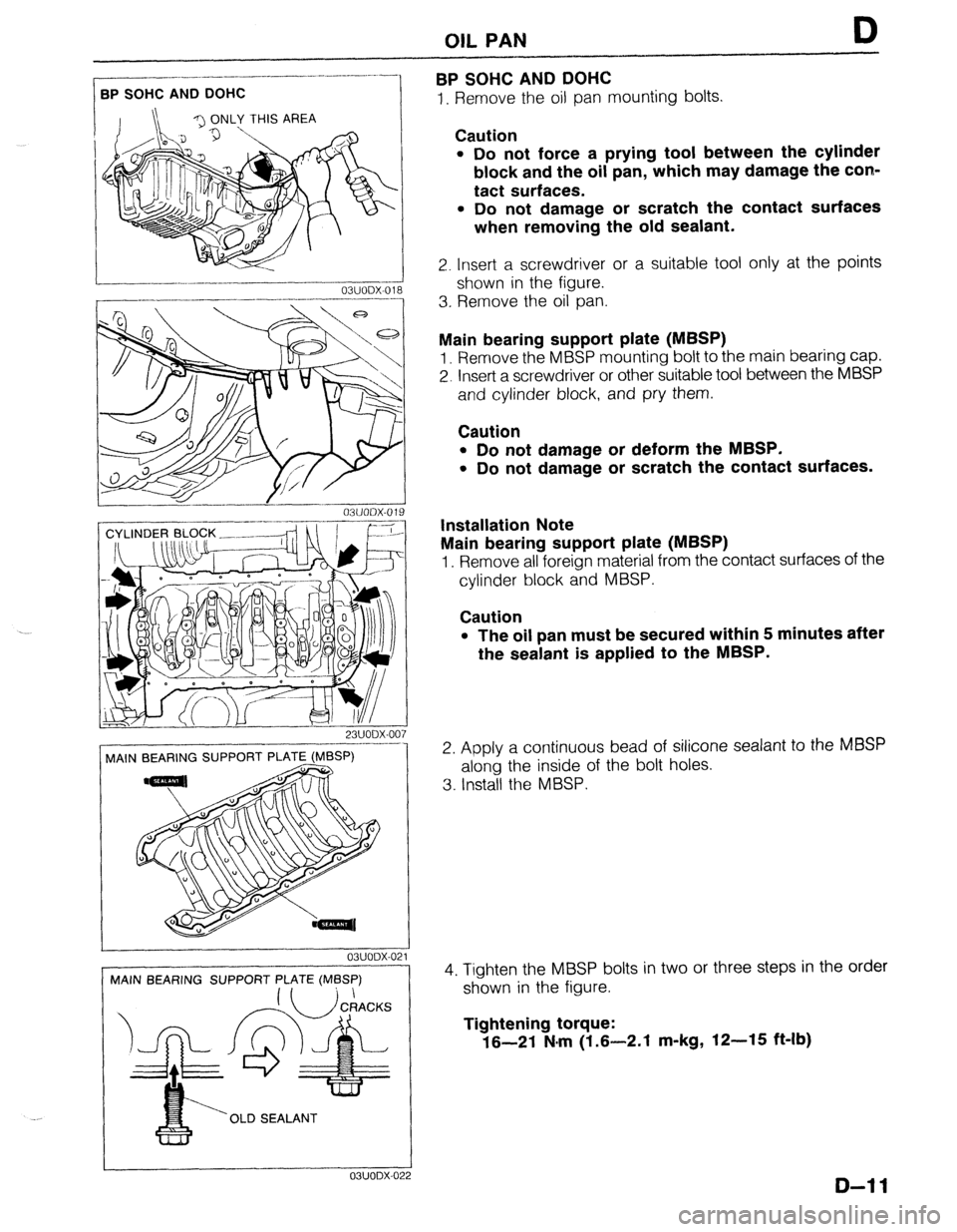
BPSOHCANDDOHC
D
I. Remove the oil pan mounting bolts. .-_-__------- BPSOHCANDDOHC
23UODX-007
MAIN BEARING SUPPORT PLATE (MBSP)
! 03UODX-021
MAIN BEARING SUPPORT PLATE (MBSP)
‘OLD SEALANT ---1_1
OBUODX-0: !2
Caution
l Do not force a prying tool between the cylinder
block and the oil pan, which may damage the con-
tact surfaces.
l Do not damage or scratch the contact surfaces
when removing the old sealant.
2. Insert a screwdriver or a suitable tool only at the points
shown in the figure.
3. Rernove the oil pan.
Main bearing support plate (MBSP)
1. Remove the MBSP mounting bolt to the main bearing cap.
2. Insert a screwdriver or other suitable tool between the MBSP
and cylinder block, and pry them.
Caution
l Do not damage or deform the MBSP.
l Do not damage or scratch the contact surfaces.
Installation Note
Main bearing support plate (MBSP)
1. Remove all foreign material from the contact surfaces of the
cylinder block and MBSP.
Caution
l The oil pan must be secured within 5 minutes after
the sealant is applied to the MBSP.
2. Apply a continuous bead of silicone sealant to the MBSP
along the inside of the bolt holes.
3. Install the MBSP.
4. Tighten the MBSP bolts in two or three steps in the order
shown in the figure.
Tightening torque:
16-21 N.m (1.6-2.1 m-kg, 12-15 ft-lb)
D-l 1
Page 246 of 1164
OIL PAN
I 03UODX.02
05UOBX.20
1
05UODX-021
56 SOHC
03UODX-02
3P s
03UODX-02!
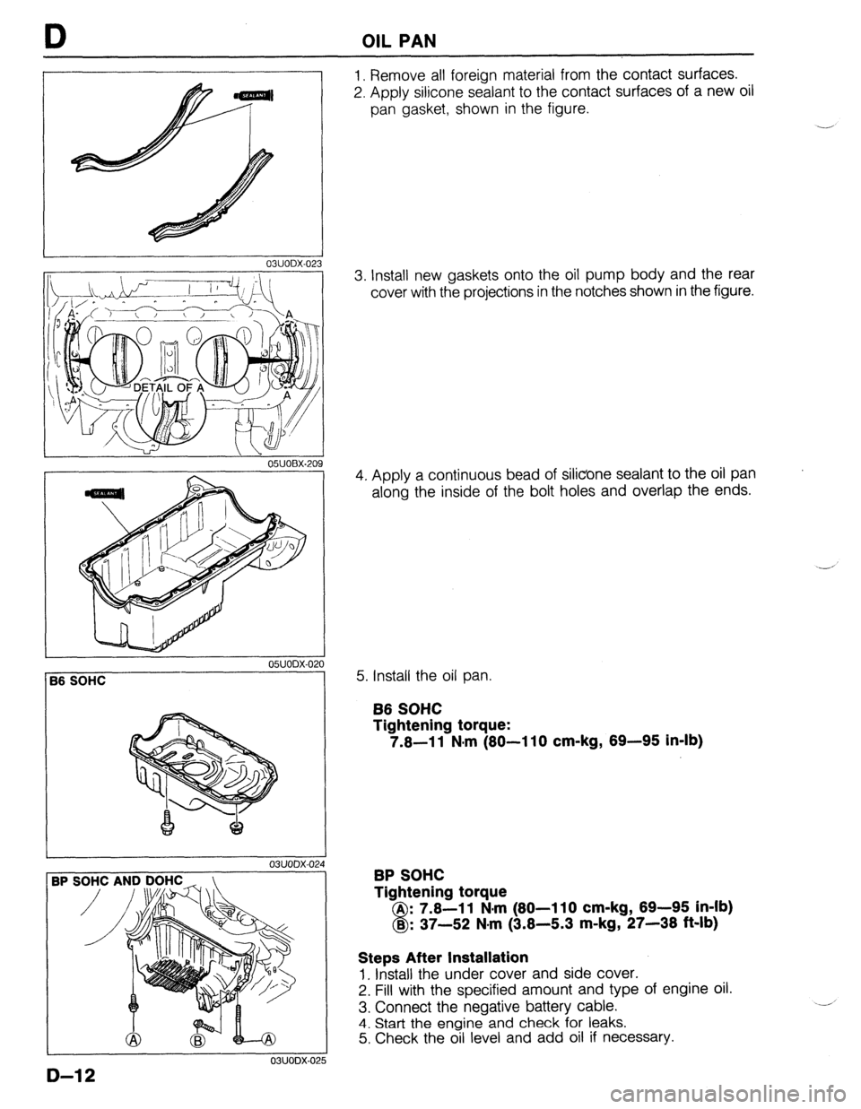
1. Remove all foreign material from the contact surfaces.
2. Apply silicone sealant to the contact surfaces of a new oil
pan gasket, shown in the figure.
3. Install new gaskets onto the oil pump body and the rear
cover with the projections in the notches shown in the figure.
4. Apply a continuous bead of silicone sealant to the oil pan
along the inside of the bolt holes and overlap the ends.
5. Install the oil pan.
B6 SOHC
Tightening torque:
7.6-11 N-m (80-110 cm-kg, 69-95 in-lb)
BP SOHC
Tightening torque
A : 7.8-l 1 N-m (80-l 10 cm-kg, 69-95 in-lb)
8 B : 37-52 N.m (3.8-5.3 m-kg, 27-38 ft-lb)
Steps After Installation
1. Install the under cover and side cover.
2. Fill with the specified amount and type of engine oil.
3. Connect the negative battery cable.
4. Start the engine and check for leaks.
5. Check the oil level and add oil if necessary.
D-12
Page 247 of 1164
OIL PUMP D
OIL PUMP
DISASSEMBLY / ASSEMBLY
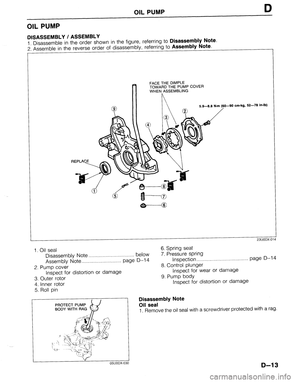
1 Disassemble in the order shown in the figure, referring to Disassembly Note.
2: Assemble in the reverse order of disassembly, referring to Assembly Note.
FACE THE DIMPLE
TOWARD THE PUMP COVER
WHEN ASSEMBLING
O-90 cm-kg, 52-78 in-lb)
-8
23UODX-014
1. Oil seal
Disassembly Note . . . . . . . . . . . . . . . . . . . . . . . . . . . . . . . below
Assembly Note .,,..,.....,..,............ page D-14
2. Pump cover
Inspect for distortion or damage 6. Spring seat
7. Pressure spring
Inspection ..,..,.....,..,..,..,.............. page D-l 4
8. Control plunger
Inspect for wear or damage
9. Pump body
3. Outer rotor
4. Inner rotor
5. Roll pin
PROTECT PUMP
BODY WITH RAG
x9 05UODX-OC IO
Inspect for distortion or damage
Disassembly Note
Oil seal
1. Remove the oil seal with a screwdriver protected with a rag.
D-13
Page 248 of 1164

OIL PUMP
OWODX-032
r----‘---I ----
L-
---- 05UODX-033
r- __I_.__^--
_- .-.. --.-.__-----^---
---7--l
L-.-.LlLd-..- ..-.---A OWODX-034
___ll_--_l___-----------
___I- 1
.i
5
INSPECTION
Pressure Spring
1 Inspect the spring for weakness or breakage.
2. Measure the free length. Replace the spring if necessary.
Free length: 45.5mm (1.791 in) -
Rotor Clearance
1. Measure the following clearances. Replace the rotor if
necessary.
Tooth tip clearance: 0.20mm (0.0079 in) max.
Outer rotor to pump body clearance:
0.22mm (0.0087 in) max.
Side clearance: 0.14mm (0.0055 in) max.
Assembly Note
Oil seal
1, Apply a small amount of clean engine oil to the lip of a new
oil seal.
2. Push the oil seal slightly in by hand,
Caution
l The oil seal must be pressed in until it is flush with
the edge of the oil pump body.
-’
3. Press the oil seal in evenly with a suitable pipe.
Oil seal outer diameter: 44mm (1.73 in)
Page 252 of 1164
E OUTLINE, TROUBLESHOOTING GUIDE
OUTLINE
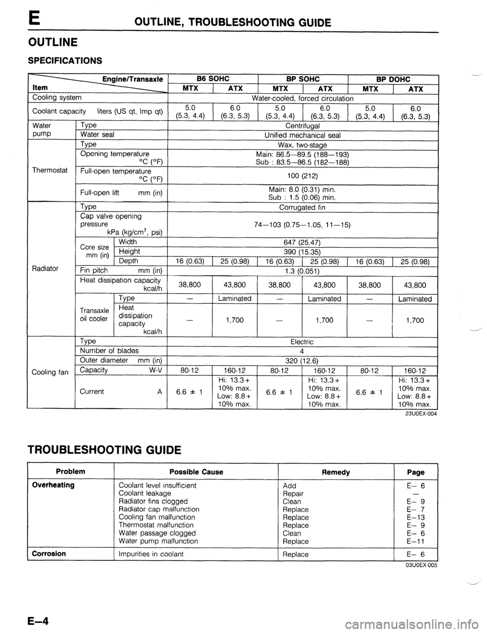
SPECIFICATIONS
B6 SOHC
BP SOHC BP DOHC
MTX
1 ATX 1 MTX ATX 1 MTX
ATX
Cooling system
Water-cooled, forced circulation
Coolant capacity liters (US qt, Imp qt) 5.0 6.0
5.0
(5.3, 4.4) (6.3, 5.3)
(5.35.04.4) (6.zi.3) (5.3, 4.4) (6.::.3)
Water
pump
Thermostat
Radiator
Cooling fan
L Type
Water seal Centrifugal
Unified mechanical seal
Type Opening temperature
‘C (OF’) Wax, two-stage
Main: 86.5-89.5 (188-193)
Sub : 83.5-86.5 (182-188)
Full-open temperature
OC (OF)
Full-open lift mm (in)
Type
Cap valve opening
pressure 100 (212)
Main: 8.0 (0.31) min.
Sub : 1.5 (0.06) min.
Corrugated fin
74-103 (0.75-1.05, 11-15)
kPa (kg/cm2, psi)
Width
Core size Height
mm (in)
Depth
Fin pitch
mm (in) 647 (25.47)
390 (15.35)
16 (0.63) 1 25 (0.98) 1 16 (0.63) 1 25 (0.98) 1 16 (0.63) 1 25 (0.98)
1.3 (0.051)
Heat dissipation capacity
kcallh 1 38,800 [ 43,800 ( 38,800 1 43,800 1 38,800 1 43,800 1
Type
Transaxle Heat
oil cooler dissipation
capacity
kcallh
Tvoe
- Laminated - Laminated -
Laminated
1,700
I .I -?nn
- -
I,,“”
I
I - I 4 Ye,-. I,IVV 1
, a-
- Electric
Number of blades 4
Outer diameter mm (in)
320 (12.6)
Capacity w-v 80-12 1 160-12 ) 80-12 ) 160-12 1 80-12 1 160-12
1 Hi: 13.3+ 1 1 Hi: 13.3+ 1 1 Hi: 13.3+
Current
TROUBLESHOOTING GUIDE I I I I
Problem Possible Cause
Overheating
Coolant level insufficient
Coolant leakage
Radiator fins clogged
Radiator cap malfunction
Cooling fan malfunction
Thermostat malfunction
Water passage clogged
Water puma malfunction .- Remedy Page
Add
Repair
Clean
Replace
Replace
Replace
Clean
Reolace E- 6
E-9
E- 7
E-13
E- 9
E- 6
E-11
I Corrosion
1 Impurities in coolant 1 Replace
I E-6 I
03UOEX-005
Page 253 of 1164

ENGINE COOLANT E
ENGINE COOLANT
PREPARATION
SST
49 9200 145
For 49 9200 146
For
inspection of inspection of
cooling system Adapter A cooling system
pressure (Part of pressure
49 9200 145)
05UOEX-00
INSPECTION
Warning
l Never remove the radiator cap while the engine is
hot.
l Wrap a thick cloth around the cap when removing it.
l When removing the radiator cap, loosen it slowly
to the first stop until the pressure in the radiator is
released, and then remove it.
03UOEX~006
Coolant Level (Engine cold)
1. Verify that the coolant level is near the radiator filler neck.
2. Remove the coolant level gauge and check the coolant level.
Coolant Quality
1. Verify that there is no buildup of rust or scale around the
radiator cap or radiator filler neck.
2. Verify that coolant is free of oil. Replace the coolant if
necessary.
Coolant Leakage
1. Connect a radiator tester (commercially available) and the
SST to the radiator filler neck.
2. Apply
103 kPa (1.05 kg/cm2, 15 psi) pressure to the
system.
3. Verify that the pressure is held.
If not, check for coolant leakage.
E-5
Page 256 of 1164

E RADIATOR
RADIATOR
REMOVAL / INSTALLATION
Caution
l Position the hose clamp in the original location on the hose, and squeeze the clamp lightly
with large pliers to ensure a good fit.
1. Disconnect the negative battery cable.
2. Drain the engine coolant.
3. Remove in the order shown in the figure.
4. Install in the reverse order of removal.
7.8-11 N.m (80-110 cm-kg, 69-95 in-lb)
-...__--- --- i
771 InFu.nnc; cvyILII ..,.,..
6. Oil cooler hose (ATX)
7. Radiator bracket
8. Radiator
Inspection . . . . . . . . . . . . . . . . . . . . . . . . . . . . . . . . . . . . . page E-9
9. Cooling fan and radiator cowling assembly 1. Resonance chamber
2. Cooling fan connector
3. Radiator thermoswitch connector (BP ATX)
4. Coolant reservoir hose
5. Radiator hose i
Y’
E-8
Page 260 of 1164

BP DOHC
L 7.8-11 N-m (60-110 cm-kg, 69-95 in-lb)
E WATER PUMP
157-167
I
(W-17, 116-123) I
I
/
I
I
I
---N-w------
---------------
----_---_
-I
N.m (m-kg, ft-lb) 1
^^, *--., ^^^
1. Timing belt
Service . . . . . . . . . . . . . . . . . . . . . . . . . . . . . . . . . . . . . . . . Section 5. Water pump assembly
B2
2. Water inlet pipe and gasket Inspect for cracks, damaged mounting
3. Water bypass pipe and O-ring surface, bearing condition, and leakage
4. Oil dip stick pipe bracket 6. Water pump gasket
Steps After Installation
1. Fill the radiator with the specified amount and type of engine coolant. (Refer to page E-6.)
2. Connect the negative battery cable,
3. Start the engine and check for leaks.
03UOEX-018
E-12
Page 265 of 1164
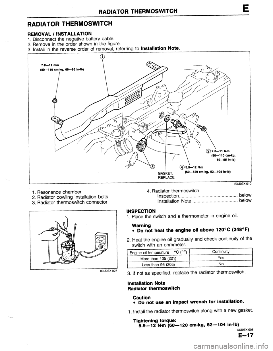
RADIATOR THERMOSWITCH E
RADIATOR THERMOSWITCH
REMOVAL / INSTALLATION
1. Disconnect the negative battery cable.
2. Remove in the order shown in the figure.
3. Install in the reverse order of removal. referrina to
Installation Note.
(80-110 cm-kg,
69-95 in-lb)
GAdKET,
REPLACE (60-120 cm-kg, 52-104 In-lb)
1. Resonance chamber
2. Radiator cowling installation bolts
3. Radiator thermoswitch connector 4. Radiator thermoswitch
Inspection . . . . . . . . . . . . . . . ..*...,..,..................* below
Installation Note ..,.,........,.......,........,... below
1. Place the switch and a thermometer in engine oil.
03UOEX-02
INSPECTION
Warning
l Do not heat the engine oil above 120°C (248OF)
2. Heat the engine oil gradually and check continuity of the
switch with an ohmmeter.
Engine oil temperature OC (OF) Continuity
More than 105 (221)
Yes
Less than 96 (205) No
3. If not as specified, replace the radiator thermoswitch.
lnstallatlon Note
Radiator thermoswitch
Caution
l Do not use an impact wrench for installation.
1. Install the radiator thermoswitch along with a new gasket.
Tightening torque:
5.9-12 N#m (60-l 20 cm-kg, 52-104 in-lb)
13UOEX-005
E-17
Page 281 of 1164
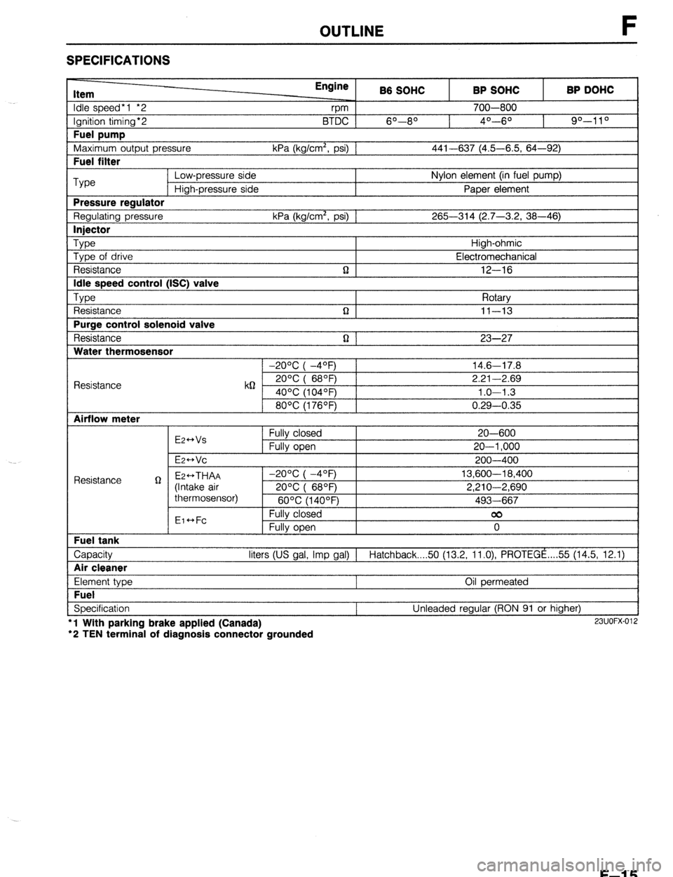
OUTLINE F
SPECIFICATIONS
Item
Idle speed*1 *2
Ignition timing*2
Fuel pump
Maximum outout Dressure Engine
rpm B6 SOHC
6O--80 BTDC 1
kPa (ka/cm’. osi1 1 BP SOHC
700-800
4O---6O BP DOHC
90-l 1 O
441-637 (4.5-6.5. 64-92) I
I Fuel filter I
Type Low-pressure side Nylon element (in fuel pump)
High-pressure side Paper element
Pressure reaulator
Regulating pressure kPa (kg/cm’, psi) 1 265-314 (2.7-3.2, 38-46)
I lniector I
Type Type of drive
Resistance
Idle speed control (ISC) valve
TvDe , ,
t Resistance
Purge control solenoid valve
Resistance
Water thermosensor n High-ohmic
Electromechanical
12-16
Rotarv
n I II-13 I
n 1 23-27
1 -20% I -4OFj 1 14.6-17.8
Resistance k62 2ooc i 68OF) 2.21-2.69
40°C (104OF) 1.0-l .3
80°C (176OF) 0.29-0.35
Airflow meter
E2++Vs
E2-Vc Fully closed
Fully open 20-600
20-l ,000
200-400
Capacity liters (US gal, Imp gal) 1 Hatchback 50 (13.2, ll.O), PROTEGE ,... 55 (14.5, 12.1)
I Air cleaner I
Element type
Fuel
Specification l
l Wlth parking brake applied (Canada)
‘2 TEN terminal of diagnosis connector grounded Oil permeated
Unleaded regular (RON 91 or higher) 23UOFX-012
F-l 5