odometer MAZDA PROTEGE 1992 Workshop Manual
[x] Cancel search | Manufacturer: MAZDA, Model Year: 1992, Model line: PROTEGE, Model: MAZDA PROTEGE 1992Pages: 1164, PDF Size: 81.9 MB
Page 919 of 1164

INSTRUMENT CLUSTER T
INSTRUMENT CLUSTER
PREPARATION
SST
I
I
49 0839 285
Checker, fuel
thermometer For
inspection of fuel
and water
temperature
gauge
I I
I
23UOTX-038
STRUCTURAL VIEW
WITH TACHOMETER (2WD)
WITHOUT TACHOMETER (2WD)
1. Speedometer 4. Fuel gauge
Troubleshooting . . . . . . . ..*................ page T-64 Troubleshooting . . . . . . . . . . . . . . . . . . . . . . . . . . page T-64
Inspection .,.......,,.......,,...,,.......... page T-71 Inspection . . . . . . . . . . . . . . . . . . . . . . . . . . . . . . . . . . . page T-71
2. Tachometer 5. Warning and indicator
Troubleshooting ..,....................... page T-64 Inspection ,.......,,......................... page T-61
inspection . . . . . . . . . . . . . . . . . . . . . . . . . . . . . . . . . . page T-71 6. Odometer
3. Water temperature gauge 7. Tripmeter
Troubleshooting . . . . . . . . . . . . . . . . . . . . . . . . . . page T-64
Inspection .,,........,,,,......,,............ page T-72
T-63
Page 927 of 1164

INSTRUMENT CLUSTER T
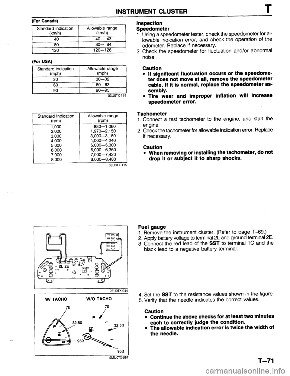
(For Canada)
(For USA)
11
OSUOTX-114
Standard Indication
(rpm)
1,000
2,000
3,000
4,000
5,000
6,000
7,000
8,000 Allowable range
@pm)
880-l ,060
1,970-2,150
3,000-3,180
4,000-4,240
5,000-5,300
6,000-6,360
7.000-7.420
8:600-8:480
03UOTX-11 5
I 23UOTX-044 WI TACHO WIO MACHO
32.50
ssn
9MUOTX-087
Inspection
Speedometer
1. Using a speedometer tester, check the speedometer for ai-
lowable indication error, and check the operation of the
odometer. Replace if necessary.
2. Check the speedometer for fluctuation and/or abnormal
noise.
Caution
l If significant fluctuation occurs or the speedome-
ter does not move at all, remove the speedometer
cable. If it is normal, replace the speedometer as-
sembly.
l Tire wear and improper inflation will Increase
speedometer error.
Tachometer
1. Connect a test tachometer to the engine, and start the
engine.
2. Check the tachometer for allowable indication error. Replace
if necessary.
Caution
l When removing or installing the tachometer, do not
drop it or subject it to sharp shocks.
Fuel gauge
1. Remove the instrument cluster. (Refer to page T-69.)
2. Apply battery voltage to terminal 2L and ground terminal 2E.
3. Connect the red lead of the
SST to terminal 1C and the
black lead to a negative battery terminal.
4. Set the
SST to the resistance values shown in the figure.
5. Verify that the needle indicates the correct values.
Caution
l Continue the above checks for at least two minutes
each to correctly judge the condition.
l The allowable indication error is twice the width of
the needle.
T-71