air bleeding MAZDA PROTEGE 1992 User Guide
[x] Cancel search | Manufacturer: MAZDA, Model Year: 1992, Model line: PROTEGE, Model: MAZDA PROTEGE 1992Pages: 1164, PDF Size: 81.9 MB
Page 672 of 1164

P CONVENTIONAL BRAKE SYSTEM
03UOPX-006
03UOPX-00
03UOPX-00
BRAKE HYDRAULIC LINE AIR BLEEDING
1. Jack up the vehicle and support it with safety stands.
Caution
l The brake fluid reservoir must be 314 full during air
bleeding.
2. Remove the bleeder cap and attach a vinyl hose to the
bleeder plug.
3. Place the other end of the vinyl tube in a clear container.
4. One person should depress the brake pedal a few times,
and then hold it in the depressed position.
5. A second person should loosen the bleeder screw, drain
out the fluid, and retighten the screw with the
SST.
Caution
l The two persons should stay in voice contact with
each other.
l Be sure the pedal remains depressed until the air
bleed screw is tightened.
6. Repeat steps 4 and 5 until no air bubbles are seen.
7. Check for correct brake operation.
8. Verify that there is no fluid leakage. Clean away any spilled
fluid with rags.
9. After bleeding the air, add brake fluid to the reservoir up
to the specified level.
Tightening torque:
5.9-8.8 N-m (0.8-0.9 m-kg, 4.3-8.5 ft-lb)
Note
l Air bleeding must be done from the bleeder screw
farthest from the disassembled parts to the nearest.
03UOPX-00
1. Brake pipe 2. Flexible hose
Inspection / Removal / Inspection / Removal /
Installation . . . . . . . . . . . . . . . . . . . . . . . . . . . . . . . . . . . page P-7 Installation . . . . . . . . . . . . . . . . . . . . . . . . . . . . . . . . . . . page P-7
P-6
Page 674 of 1164

P CONVENTIONAL BRAKE SYSTEM
03UOPX.01
03UOPX-01
03UOPX-01
23UOPX-0
BRAKE FLUID
Inspection
Leakage inspection
Depress the brake pedal several times, and inspect for leak-
age of the brake line system. __,
Brake Fluid Level
Leakage check
Verify that the fluid level in the reservoir is between the MAX
and MIN lines on the reservoir.
Add fluid if it is below MAX.
Replacement
1. Follow the procedure outlined in Air Bleeding.
(Refer to page P-6).
2. Continue bleeding and replacing the brake fluid until only
clean fluid is expelled.
3. Fill the reservoir to the MAX level.
BRAKEPEDAL
Inspection, On-vehicle
Brake pedal height
Inspection
Verify that the distance from the center on the pedal pad to
the floor mat is as specified.
Specification: 193-196mm (7.60-7.72 in)
Adjustment
1. Disconnect the stoplight switch connector.
2. Loosen locknuts @J and turn switch @ until it does not con-
tact the pedal.
3. Loosen locknuts (I?J and turn rod @ to adjust the height
of the brake pedal.
4. Tighten the stoplight switch until it contacts the pedal; then
turn it an additional 112 turn. Tighten locknuts @ and @I.
5. Connect the stoplight switch connector.
6. Verify operation of the stoplights.
P-8
Page 679 of 1164

CONVENTIONALBRAKESYSTEM P
1 SUOPX-001
03UOPX-03
0
o3uoPx-os
0
POWER BRAKE UNIT
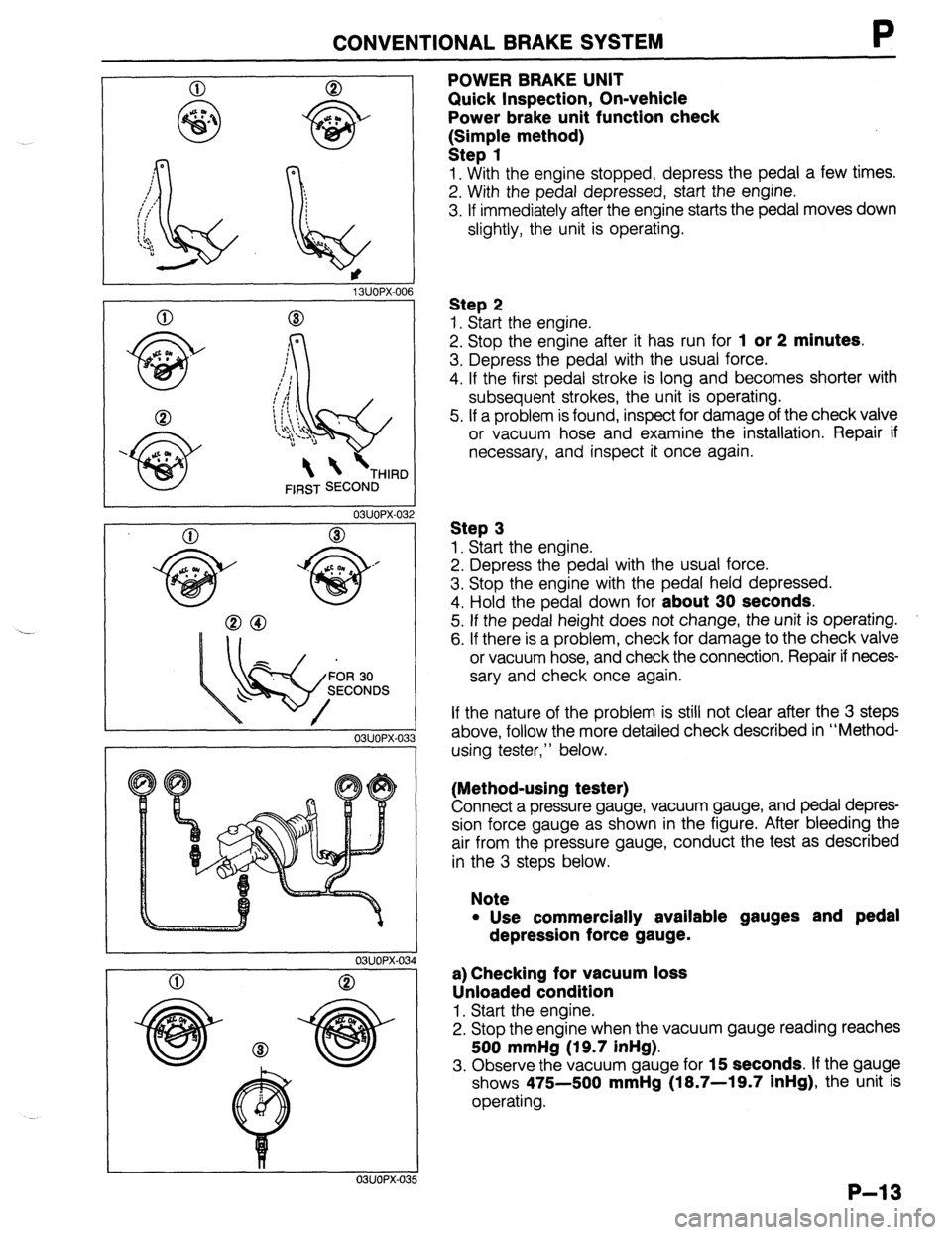
Quick Inspection, On-vehicle
Power brake unit function check
k:;;p{e method)
1. With the engine stopped, depress the pedal a few times.
2. With the pedal depressed, start the engine.
3. If immediately after the engine starts the pedal moves down
slightly, the unit is operating.
Step 2
1. Start the engine.
2. Stop the engine after it has run for
1 or 2 minutes.
3. Depress the pedal with the usual force.
4. If the first pedal stroke is long and becomes shorter with
subsequent strokes, the unit is operating.
5. If a problem is found, inspect for damage of the check valve
or vacuum hose and examine the installation. Repair if
necessary, and inspect it once again.
Step 3
1. Start the engine.
2. Depress the pedal with the usual force.
3. Stop the engine with the pedal held depressed.
4. Hold the pedal down for
about 30 seconds.
5. If the pedal height does not change, the unit is operating.
6. If there is a problem, check for damage to the check valve
or vacuum hose, and check the connection. Repair if neces-
sary and check once again.
If the nature of the problem is still not clear after the 3 steps
above, follow the more detailed check described in “Method-
using tester,” below.
(Method-using tester)
Connect a pressure gauge, vacuum gauge, and pedal depres-
sion force gauge as shown in the figure. After bleeding the
air from the pressure gauge, conduct the test as described
in the 3 steps below.
Note
l Use commercially available gauges and pedal
depression force gauge.
a) Checking for vacuum loss
Unloaded condition
1. Start the engine.
2. Stop the engine when the vacuum gauge reading reaches
500 mmHg (19.7 inHg).
3. Observe the vacuum gauge for 15 seconds. If the gauge
shows 475-500
mmHg (18.7-19.7 inHg), the unit is
operating.
P-13