brake sensor MAZDA PROTEGE 1992 Workshop Manual
[x] Cancel search | Manufacturer: MAZDA, Model Year: 1992, Model line: PROTEGE, Model: MAZDA PROTEGE 1992Pages: 1164, PDF Size: 81.9 MB
Page 281 of 1164

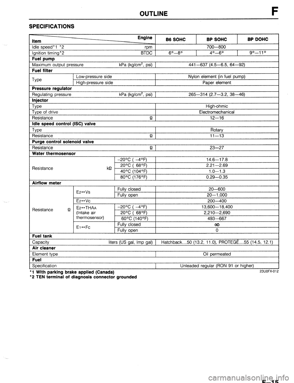
OUTLINE F
SPECIFICATIONS
Item
Idle speed*1 *2
Ignition timing*2
Fuel pump
Maximum outout Dressure Engine
rpm B6 SOHC
6O--80 BTDC 1
kPa (ka/cm’. osi1 1 BP SOHC
700-800
4O---6O BP DOHC
90-l 1 O
441-637 (4.5-6.5. 64-92) I
I Fuel filter I
Type Low-pressure side Nylon element (in fuel pump)
High-pressure side Paper element
Pressure reaulator
Regulating pressure kPa (kg/cm’, psi) 1 265-314 (2.7-3.2, 38-46)
I lniector I
Type Type of drive
Resistance
Idle speed control (ISC) valve
TvDe , ,
t Resistance
Purge control solenoid valve
Resistance
Water thermosensor n High-ohmic
Electromechanical
12-16
Rotarv
n I II-13 I
n 1 23-27
1 -20% I -4OFj 1 14.6-17.8
Resistance k62 2ooc i 68OF) 2.21-2.69
40°C (104OF) 1.0-l .3
80°C (176OF) 0.29-0.35
Airflow meter
E2++Vs
E2-Vc Fully closed
Fully open 20-600
20-l ,000
200-400
Capacity liters (US gal, Imp gal) 1 Hatchback 50 (13.2, ll.O), PROTEGE ,... 55 (14.5, 12.1)
I Air cleaner I
Element type
Fuel
Specification l
l Wlth parking brake applied (Canada)
‘2 TEN terminal of diagnosis connector grounded Oil permeated
Unleaded regular (RON 91 or higher) 23UOFX-012
F-l 5
Page 315 of 1164

TROUBLESHOOTING GUIDE F
12 ROUGH IDLE/ENGINE STALLS JUST AFTER STARTING
DESCRIP-
*Engine starts normally but vibrates excessively or stalls just after starting (acceleration from idle) TION
*Idle conditions are normal in the other conditions [TROUBLESHOOTING HINTS]
@ Fuel injection control system or idle speed control sys-
@ Idle speed misadjustment
tern malfunction @ Ignition timing misadjustment
*Start signal not input to ECU iTEl
-s-- 3
4
5 INSPECTION
-T- ACTION
Check if “00” is displayed on Self-Diagnosis
Checker with ignition switch ON w page F-82
SYSTEM,SELECT: I
r -SELECT SW: A
Check if ECU terminal voltages are OK
MTX...Especially 1 N
ATX... Especially 1T w page F-150
Connect System Selector to diagnosis connector
and set Test Switch to “SELF TEST” and check
for correct ignition timing at idle after warm-up w page F-78
Ignition timing (BTDC)
l BP DOHC : 9”-11 o l BP SOHC : 4O--6O
l B8 : 60-80
Check continuity between throttle sensor termi-
nals IDL and E CT page F-159
MTX
Clearance between throttle
lever and stopper
MTX O.lmm (0.004 in)
1 .Omm (0.039 in)
ATX 0.1 mm (0.004 in)
0.6mm (0.024 in) Continuity
Yes
No
Yes
No
Try known good ECU and check if condition
mproves w page F-149 Yes
No
Yes
Go to next step No
Check for cause Yes
In same condition as Step 3 inspection
and apply parking brake
Check for correct idle speed w page F-80
Idle speed: 700-800 rpm
No
Adjust Yes
Go to next step No
Adjust Go to next step Service Code No. displayed
Check for cause (Refer to specified
check sequence) w page F-83
“88” flashes
Check ECU terminal IF voltage w page F-150
Specification: Battery voltage
(Ignition switch ON)
d If OK, replace ECU w page F-149
* If not OK, check wiring between
ECU and Self-Diagnosis Checker c7 page F-151
3 If OK, go to next step
3 If not OK, adjust idle speed w page F-80
w page F-79
w page F-159
F-49
Page 374 of 1164

SELF-DIAGNOSIS FUNCTION
Throttle sensor
Depress accelerator pedal (not fully) and check that
monitor lamp illuminates
YES NO
PC: *Throttle sensor malfunction CT page F-169
*Short circuit in wire harness
from throttle sensor to ECU
*ECU terminal 1 N (MTX) 1T
(ATX) voltage incorrect CT page F-150
l ECU malfunction
Depress acceleration pedal fully and check that monitor
No : PC: *Throttle sensor malfunction w page F-169
lamp does not illuminate *Open circuit in wire harness
from throttle sensor to ECU
YES *ECU terminal 2L (MTX) or 21
(ATX) voltage incorrect a page F-154
Throttle sensor OK
Release accelerator pedal
23UOFX-090
Stoplight switch
Depress brake pedal
Check that monitor lamp illuminates
YES
Stoplight switch OK
Release brake pedal NO
PC: *Stoplight switch malfunction w Section T
*Open circuit in wire harness
1
from stoplight switch to ECU
*ECU terminal 10 (MTX) 1Q
(ATX) voltage incorrect CT page F-l 52
l ECU malfunction
23UOFX-091
Blower switch
---
Turn blower switch to 2nd or higher position
Check that monitor lamp illuminates
YES
Blower switch OK NO
__L PC: *Blower switch malfunction
*Open circuit in wire harness
from blower switch to ECU
l ECU terminal 1 S (MTX) 1 P
(ATX) voltage incorrect
l ECU malfunction p Section T
w page F-152
23UOFX-092
F-l 08
Page 418 of 1164

F CONTROL SYSTEM
VB: Battery voltage
erminal Input Output Connection to Test condition Corrsct voltage Remark
1M - - - - - -
IN 0 Throttle sensor Accelerator pedal released ov Ignition switch
(Idle switch)
Accelerator pedal depressed
VB ON
10 0
1P 0 Stoplight switch
P/S pressure
switch Brake pedal released
Brake pedal depressed
Ignition switch ON
P/S ON at idle
P/S OFF at idle ov
-
VEi
Va
ov
VS -
10 0 A/C switch A/C switch ON
A/C switch OFF Below 23 Ignition switch
VS ON and blower
motor ON
1R 0
IS 0 Fan switch
Blower control
switch Fan operating (Engine coolant tempera-
ture over 97% (207OF) or diagnosis con-
nector terminal TFA grounded)
Fan not operating (Idle)
Blower control switch OFF or 1st position
Blower control switch 2nd or higher po-
sition ov
-
V0
Ve ignition switch
ov ON
IT 0 Rear window
defroster switch Rear window defroster switch OFF
Rear window defroster switch ON ov
VB
Ignition switch ON
1u 0
iv 0 Headlight switch
Neutral/Clutch
switches Headlights ON
Headlights OFF
Neutral position or clutch pedal
depressed
Others V0
-
ov
ov
VB -
1 I lr----t
r-i
ul r
2Y 2w 2u 2s 20 20 2M 2K 21 2G 2E 2’3 2A 1lJ 1s IQ 10 1M 1K 11 1G 1E 1~ 1A
22 2x 2v 2T 2R 2P 2N 2L 2J 34 2t= 2D 28 Ii/ fT 1R 1p IN 1L 1J 1H 1F 1D 18
F-l 52
Page 426 of 1164

CONTROL SYSTEM
VB: Battery voltage
erminal Input Output
Connection to Test condition Correct voltage
Remark
1L
0 A/C relay Ignition switch ON VB
A/C switch ON at idle Below 2.5V
A/C switch OFF at idle V0
-
1M 0
1N 0 Vehicle speed
sensor
P/S pressure
switch While driving 4--5v
Vehicle stopped 0 or 8V
Ignition switch ON
VB
P/S ON at idle
ov
P/S OFF at idle Vi3 -
-
10 0 A/C switch A/C switch ON
A/C switch OFF Below 2.5V ignition switch
VB ON and blower
motor ON
IP 0 Blower control
switch Blower control switch OFF or 1st position Ve ignition switch
Blower control switch 2nd or higher po- Below 1 .OV ON
sition
1Q 0
1R 0
1s 0
IT 0 Stoplight switch Brake pedal released Below 1 .OV
-
Brake pedal depressed VI3
Inhibitor switch N or P range ov Ignition switch
(P, N ranges) ON
Other range VI3
Cruise control main Normal condition
VB Ignition switch
switch ON
Set or Resume switch ON or vehicle speed Below 1 .OV
8 km/h (5 mph) lower than preset speed
(Driving vehicle cruise control operation)
Throttle sensor Accelerator pedal released Below 1 .OV Ignition switch
(Idle switch)
Accelerator pedal depressed V0 ON
1u - - -
- - -
1v - - - -
- -
2A 0 Distributor Ignition switch ON Approx. OV
(Ne-signal) or 5V -
Idle Approx. 2V
LY”“l I. A3 311 blFY.1.
J
- .*
F-160
Page 669 of 1164

OUTLINE
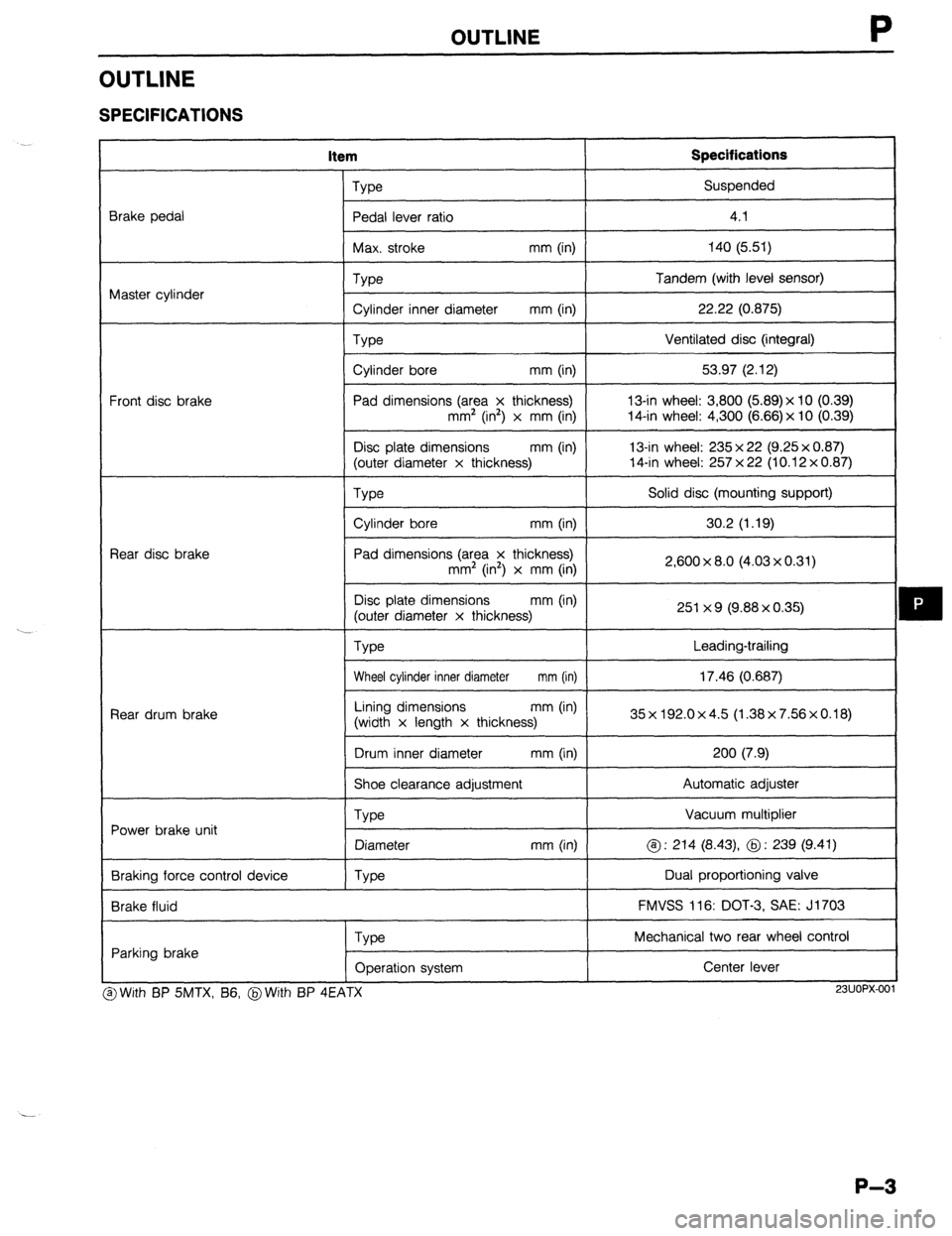
OUTLINE
SPECIFICATIONS
item Specifications
Brake pedal
Master cylinder
Front disc brake
Rear disc brake
Rear drum brake
Power brake unit
Braking force control device
Brake fluid Type Suspended
Pedal lever ratio
I 4.1
I
Max. stroke mm (in) 140 (5.51)
I
Type
Cylinder inner diameter mm (in)
Type
Cylinder bore mm (in)
Pad dimensions (area x thickness)
mm’ (in2) x mm (in)
Disc plate dimensions mm (in)
(outer diameter x thickness) Tandem (with level sensor)
22.22 (0.875)
Ventilated disc (integral)
53.97 (2.12)
13-in wheel: 3,800 (5.89)x 10 (0.39)
14-in wheel: 4,300 (6.66) x 10 (0.39)
13-in wheel: 235 x 22 (9.25 x 0.87)
14-in wheel: 257 x 22 (10.12 x 0.87)
We
I Solid disc (mounting support)
I
Cylinder bore mm (in)
I 30.2 (1.19)
I
Pad dimensions (area x thickness)
mm2 (in’) x mm (in)
Disc plate dimensions mm (in)
(outer diameter x thickness)
Type 2,600 x 8.0 (4.03 x 0.31)
251 x 9 (9.88 x 0.35)
Leading-trailing
Wheel cylinder inner diameter mm (in) 17.46 (0.687)
I
Lining dimensions mm (in)
(width x length x thickness) 35x192.0x4.5 (1.38x7.56x0.18)
I
Drum inner diameter mm (in) 200 (7.9)
I
Shoe clearance adjustment Automatic adjuster
Vacuum multiplier
@ : 214 (8.43) @ : 239 (9.41)
Dual proportioning valve
FMVSS 116: DOT-3, SAE: J1703
Type
Diameter
Type mm (in)
Parking brake
Type
Operation system Mechanical two rear wheel control
Center lever I
3 With BP SMTX, B6, @With BP 4EATX
I I
23UOPX-001
P-3
Page 678 of 1164

P CONVENTIONAL BRAKE SYSTEM
Disassembly / Assembly / Inspection
1. After removing the brake fluid, disassemble in the order shown in the figure.
2. Inspect all parts and repair or replace as necessary.
3. Assemble in the reverse order of disassembly.
Caution
l Secure the master cylinder flange in a vise when necessary.
l Replace the piston assembly, if necessary.
l Do not let foreign material enter the cylinder, and do not scratch the inside of the cylinder
or the outer surface of the piston.
REP1 .ACE
0.98-1.47 (10-15, 8.7-13.0)
o R,NG ,,,dcE @.96-2.45 (20-25, 17.4-21.7)
- 3
N.m (cm-kg, in-lb)
1. Reservoir cap assembly 5. Bushing 9. Primary piston assembly
2. Float 6. Stopper screw 10. Secondary piston assembly
3. Screw 7. Fluid level sensor 11. Master cylinder body
4. Reservoir 8. Snap ring
P-12
Page 917 of 1164

WARNING SYSTEM T
13UOTX-07
63U15X-05
, I//
‘nF -
-
-
FUEL
13UOTX.08C
- CHARGE
13UOTX-08
13UOTX-08
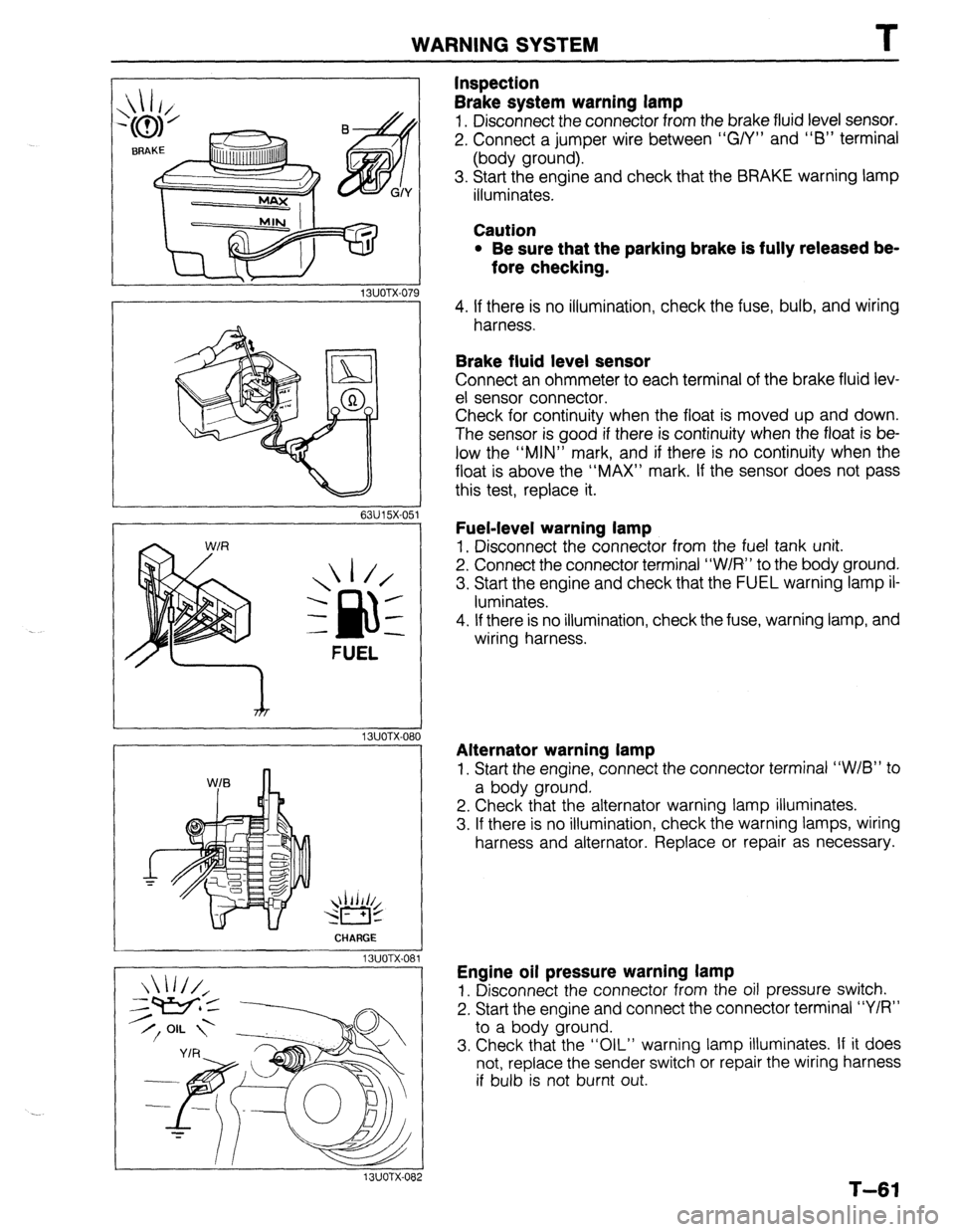
Inspection
Brake system warning lamp
1. Disconnect the connector from the brake fluid level sensor.
2. Connect a jumper wire between “G/Y” and “6” terminal
(body ground).
3. Start the engine and check that the BRAKE warning lamp
illuminates.
Caution
l Be sure that the parking brake is fully released be-
fore checking.
4. If there is no illumination, check the fuse, bulb, and wiring
harness.
Brake fluid level sensor
Connect an ohmmeter to each terminal of the brake fluid lev-
el sensor connector.
Check for continuity when the float is moved up and down.
The sensor is good if there is continuity when the float is be-
low the “MIN” mark, and if there is no continuity when the
float is above the “MAX” mark. If the sensor does not pass
this test, replace it.
Fuel-level warning lamp
1. Disconnect the connector from the fuel tank unit.
2. Connect the connector terminal “W/R” to the body ground.
3. Start the engine and check that the FUEL warning lamp il-
luminates.
4. If there is no illumination, check the fuse, warning lamp, and
wiring harness.
Alternator warning lamp
1. Start the engine, connect the connector terminal “W/B” to
a body ground.
2. Check that the alternator warning lamp illuminates.
3. If there is no illumination, check the warning lamps, wiring
harness and alternator. Replace or repair as necessary.
Engine oil pressure warning lamp
1. Disconnect the connector from the oil pressure switch.
2. Start the engine and connect the connector terminal “Y/R”
to a body ground.
3. Check that the “OIL” warning lamp illuminates. If it does
not, replace the sender switch or repair the wiring harness
if bulb is not burnt out.
T-61
Page 920 of 1164

2L BUZZER 2A 28 2C 2D 1A 3K l--r nnmn
I I‘ I
1C 3L 2E 2G IL iG 1F 1D tB
3F 38 3G 1E 3D
l-l rt
II l-l
l-l It II l-l 1J 11 1H
1G IF 1E 1D 1C 1B 1A 2L 2K 2J 21 2H 2G 2F 2E 2D 2C 28 2A
r-l It ,I 3L 3K 3J 31 3H 3G 3F 3E 3D 3C 3B 3A
Ter- I I minal Connected to 1 1A Combination switch
1B Ground
IC Fuel tank unit
1 ID 1 EGI control unit
I
II L 1J 1
L Ter-
minal Connected to
2A Speed sensor output
28 Light switch (high beam)
2C Turn switch (L)
20 Turn switch (R)
2E Ground
2F Ground
2L 1 IGI battery Ter-
minal Connected to
3A
38 Alternator
3c
30 Oil pressure switch
3E
3F Parking brake switch, Brake fluid switch
3G Passive shoulder belt control unit
3H h
I 31
3J
3K
IG2 battery
3L Water temperature gauge unit
Page 938 of 1164

CRUISE CONTROL SYSTEM
I
23UOTX-056
1 23UOTX-057
Inspection Procedure
Quick inspection of cruise control system
1. Locate the cruise control connector.
2. Connect a 1.4W test light between terminals f and d, with
connector attached to control unit. -1
Note
l There is no wire in terminal d of the connector. Push
the test light through the connector and touch the
corresponding pin on the control unit.
3. Turn the ignition switch to ON.
4. Verify that the MAIN switch is OFF. (The MAIN indicator lamp
is OFF.)
5. Press the RESUMElACCEL switch and the MAIN switch
simultaneously to activate the system inspection. (The MAIN
indicator lamp will come ON.)
6. Operate each switch as described below and verify the oper-
ation codes.
7. Press the MAIN switch to deactivate the system inspection.
(The MAIN indicator lamp will go OFF.)
Note
l The cruise control system will not operate when in
the self-diagnosis mode.
Operation Code Numbers
Inspection of cruise control system
The test light will flash if the system is operating correctly. If the light fails to flash, inspect the system.
Note
l Shift the selector lever to D or R range before operating the inspection. (For ATX)
l Shift to the gear except the neutral position. (For MTX)
Procedure
Press SET/COAST switch Pattern of output signal Code
(Test light) No. Actlon to inspect ON
n II 21 Inspect cruise control switch
(Refer to page T-21)
OFF
Press RESUMElACCEL switch
ON
n 22 inspect cruise control switch
(Refer to page T-21)
OFF
Depress brake pedal
ON
n ml 31 Inspect stoplight switches
(Refer to pages T-47 and
OFF T-88)
Turn ignition switch to ON and shift the ON 35 Inspect inhibitor switch
selector lever to P or N range (For ATX) (Refer to Section K) or clutch
Depress clutch pedal (For MTX) switch (Refer to Section F)
OFF
Drive vehicle above 40 km/h (25 mph) ON 37 Inspect speed sensor or wire
harness
OFF
I
1
. . . _
T-82