brake light MAZDA PROTEGE 1992 User Guide
[x] Cancel search | Manufacturer: MAZDA, Model Year: 1992, Model line: PROTEGE, Model: MAZDA PROTEGE 1992Pages: 1164, PDF Size: 81.9 MB
Page 679 of 1164

CONVENTIONALBRAKESYSTEM P
1 SUOPX-001
03UOPX-03
0
o3uoPx-os
0
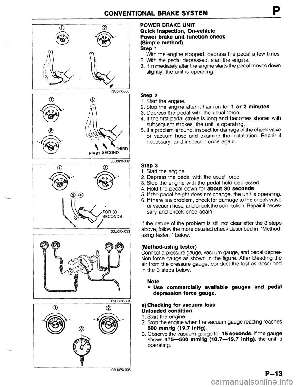
POWER BRAKE UNIT
Quick Inspection, On-vehicle
Power brake unit function check
k:;;p{e method)
1. With the engine stopped, depress the pedal a few times.
2. With the pedal depressed, start the engine.
3. If immediately after the engine starts the pedal moves down
slightly, the unit is operating.
Step 2
1. Start the engine.
2. Stop the engine after it has run for
1 or 2 minutes.
3. Depress the pedal with the usual force.
4. If the first pedal stroke is long and becomes shorter with
subsequent strokes, the unit is operating.
5. If a problem is found, inspect for damage of the check valve
or vacuum hose and examine the installation. Repair if
necessary, and inspect it once again.
Step 3
1. Start the engine.
2. Depress the pedal with the usual force.
3. Stop the engine with the pedal held depressed.
4. Hold the pedal down for
about 30 seconds.
5. If the pedal height does not change, the unit is operating.
6. If there is a problem, check for damage to the check valve
or vacuum hose, and check the connection. Repair if neces-
sary and check once again.
If the nature of the problem is still not clear after the 3 steps
above, follow the more detailed check described in “Method-
using tester,” below.
(Method-using tester)
Connect a pressure gauge, vacuum gauge, and pedal depres-
sion force gauge as shown in the figure. After bleeding the
air from the pressure gauge, conduct the test as described
in the 3 steps below.
Note
l Use commercially available gauges and pedal
depression force gauge.
a) Checking for vacuum loss
Unloaded condition
1. Start the engine.
2. Stop the engine when the vacuum gauge reading reaches
500 mmHg (19.7 inHg).
3. Observe the vacuum gauge for 15 seconds. If the gauge
shows 475-500
mmHg (18.7-19.7 inHg), the unit is
operating.
P-13
Page 867 of 1164

TROUBLESHOOTING GUIDE T
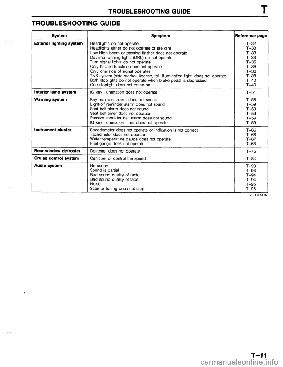
TROUBLESHOOTING GUIDE
System
Exterior lighting system
Interior lamp system
Warning system
Instrument cluster
Rear window defroster
Cruise control system
Audio system Symptom Reference page
Headlights do not operate T-32
Headlights either do not operate or are dim T-33
Low-High beam or passing flasher does not operate T-33
Daytime running lights (DRL) do not operate T-33
Turn signal lights do not operate T-35
Only hazard function does not operate T-36
Only one side of signal operates
T-36
TNS system (side marker, license, tail, illumination light) does not operate T-38
Both stoplights do not operate when brake pedal is depressed T-40
One stoplight does not come on T-40
IG key illumination does not operate
T-51
Key reminder alarm does not sound
Light-off reminder alarm does not sound
Seat belt alarm does not sound
Seat belt timer does not operate
Passive shoulder belt alarm does not sound
IG key illumination timer does not operate T-58
T-59
T-59
T-59
T-59
T-59
Speedometer does not operate or indication is not correct
Tachometer does not operate
Water temperature gauge does not operate
Fuel gauge does not operate
Defroster does not operate
Can’t set or control the speed T-65
T-66
T-67
T-68
T-76
T-84
No sound
Sound is partial
Bad sound quality of radio
Bad sound quality of tape
Noise
Scan or tuning does not stop T-93
T-93
T-94
T-94
T-95
T-95
T-l 1
Page 889 of 1164

EXTERIOR LIGHTING SYSTEM T
Headlights either do not operate or are dim Low-High beam or passing flasher does not
J operate
Burnt out bulb or poor grounding J
03UOTX-049 Defective combination switch
03UOTX-050
(Canada) Daytime running lights (DRL) do not operate
Confirm that headlights operate with the light switch ON
(second position) OK
Turn OFF the light switch and turn ON the ignition
switch when parking level pulling
I
Check head 30A main fuse OK
Check DRL resistor OK Repair DRL resistor 10A fuse
Confirm battery voltage on R and L/G wire of the DRL NG
relay Repair harness (Fuse - DRL relay)
I
I
Check the DRL relay
Repair DRL relay
1 OK
Confirm battery voltage on (BRNV) wire of the DRL con-
trol unit NG
Repair harness (DRL relay - DRL control unit) OK
Confirm battery voltage on (L/G) wire of the DRL control NG
unit Repair harness (Rear wiper fuse - DRL control unit) OK
Confirm continuity of (G/R) wire of the DRL control unit x Repair harness (DRL control unit - Parking brake
to ground switch) or check the parking brake switch 1 OK
Confirm continuity on (B) wire of the DRL control unit to
NG
ground Repair harness (DRL control unit ground) OK
-1 NG
Confirm approx. 8V on the DRL resistor Repair harness (DRL control unit - DRL headlight)
I
Confirm battery voltage on (
Confirm approx. 8V on (R/W) wire of the DRL resistor Repair harness (DRL resistor - DRL relay)
Repair harness (DRL control unit - DRL resistor)
23UOTX-019
T-33
Page 896 of 1164

I
EXTERIOR LIGHTING SYSTEM
Both stoplights do not operate when brake pedal is
depressed
i
Check stop 20A fuse
I Short circuit
Confirm battery voltage on G/W wire of the stoplight
switch
I Repair harness (Fuse - Stoplight switch) OK
Check the voltage with the brake pedal depressed
I
BD
c
Confirm battery voltage on G Replace the stoplight switch
8) OK
Confirm battery voltage on G Repair harness (Stoplight switch - Stoplight)
(B
Confirm continuity on B wir Repair harness (Stoplight - Body ground)
I I I
I
Replace the bulb
I
23UOTX-023 One stoplight does not come on
Burnt out bulb or faulty grounding
03UOTX-058
T-40
Page 903 of 1164

EXTERIOR LIGHTING SYSTEM T
03UOTX-07
STOPLIGHT SWITCH
Inspection
1. Remove the stoplight switch connector.
2. Connect an ohmmeter between terminals of the stoplight
switch.
3. Confirm continuity between the terminals when the brake
pedal is depressed.
SACK-UP LIGHT SWITCH (For MTX)
Inspection
1. Remove the back-up light switch connector.
2. Shift to the reverse position.
3. Confirm continuity between the R/G and the B/Y wire of the
connector.
LICENSE PLATE LIGHT
Removal / Inspection / Installation
1. Remove in the order shown in the figure.
2. inspect all parts and repair or replace as necessary
3. Install in the reverse order of removal.
PROTEGi
1. Nut
2. Gasket
3. Bulb 4. License plate light (Rear finisher)
Visual inspection
T-47
Page 920 of 1164

2L BUZZER 2A 28 2C 2D 1A 3K l--r nnmn
I I‘ I
1C 3L 2E 2G IL iG 1F 1D tB
3F 38 3G 1E 3D
l-l rt
II l-l
l-l It II l-l 1J 11 1H
1G IF 1E 1D 1C 1B 1A 2L 2K 2J 21 2H 2G 2F 2E 2D 2C 28 2A
r-l It ,I 3L 3K 3J 31 3H 3G 3F 3E 3D 3C 3B 3A
Ter- I I minal Connected to 1 1A Combination switch
1B Ground
IC Fuel tank unit
1 ID 1 EGI control unit
I
II L 1J 1
L Ter-
minal Connected to
2A Speed sensor output
28 Light switch (high beam)
2C Turn switch (L)
20 Turn switch (R)
2E Ground
2F Ground
2L 1 IGI battery Ter-
minal Connected to
3A
38 Alternator
3c
30 Oil pressure switch
3E
3F Parking brake switch, Brake fluid switch
3G Passive shoulder belt control unit
3H h
I 31
3J
3K
IG2 battery
3L Water temperature gauge unit
Page 938 of 1164

CRUISE CONTROL SYSTEM
I
23UOTX-056
1 23UOTX-057
Inspection Procedure
Quick inspection of cruise control system
1. Locate the cruise control connector.
2. Connect a 1.4W test light between terminals f and d, with
connector attached to control unit. -1
Note
l There is no wire in terminal d of the connector. Push
the test light through the connector and touch the
corresponding pin on the control unit.
3. Turn the ignition switch to ON.
4. Verify that the MAIN switch is OFF. (The MAIN indicator lamp
is OFF.)
5. Press the RESUMElACCEL switch and the MAIN switch
simultaneously to activate the system inspection. (The MAIN
indicator lamp will come ON.)
6. Operate each switch as described below and verify the oper-
ation codes.
7. Press the MAIN switch to deactivate the system inspection.
(The MAIN indicator lamp will go OFF.)
Note
l The cruise control system will not operate when in
the self-diagnosis mode.
Operation Code Numbers
Inspection of cruise control system
The test light will flash if the system is operating correctly. If the light fails to flash, inspect the system.
Note
l Shift the selector lever to D or R range before operating the inspection. (For ATX)
l Shift to the gear except the neutral position. (For MTX)
Procedure
Press SET/COAST switch Pattern of output signal Code
(Test light) No. Actlon to inspect ON
n II 21 Inspect cruise control switch
(Refer to page T-21)
OFF
Press RESUMElACCEL switch
ON
n 22 inspect cruise control switch
(Refer to page T-21)
OFF
Depress brake pedal
ON
n ml 31 Inspect stoplight switches
(Refer to pages T-47 and
OFF T-88)
Turn ignition switch to ON and shift the ON 35 Inspect inhibitor switch
selector lever to P or N range (For ATX) (Refer to Section K) or clutch
Depress clutch pedal (For MTX) switch (Refer to Section F)
OFF
Drive vehicle above 40 km/h (25 mph) ON 37 Inspect speed sensor or wire
harness
OFF
I
1
. . . _
T-82
Page 942 of 1164

I
CRUISE CONTROL SYSTEM
s q 0 m
9 e c a
t rpn i j
h
f d b
*
Inspection
Cruise control unit
1. Connect a voltmeter between cruise control unit and ground.
2. Turn the ignition switch ON and check the terminal voltages
as described below.
03UOTX-146
VB: Batterv voltage
c (Output) Actuator
I ov
Approx. 9V
e (Input)
I Cruise control main
I
VB switch (NC)
f (Input)
9 Wv-4 Cruise control main
switch (N.0)
EC-AT control unit
VB
V0
h (Output) (only ATX)
Stoplight switch 2 (N.C) Approx. 9V
i (hW Note I
Inhibitor switch (ATX)
I ov
Approx. 5V Disconnect t
EGI control
Clutch switch (MTX)
ov unit connector Approx. 5V
Cruise control switch
(Set/coast switch) V0
Approx. 5V unit connector
a
S I Battery
I VI3 t
1 Ground I ov Procedure
Ignition switch ON
Main switch ON
Ignition switch ON
Main switch ON
ignition switch ON
Main switch ON
Ignition switch ON
Main switch ON
Ignition switch ON
Main switch ON
“N” or “P” range and main switch ON
Other range and main switch ON
Clutch pedal depressed and main switch ON
Main switch ON
Horn switch OFF
Ignition switch ON
Brake pedal depressed
Main switch ON
While pushing the resumelaccel switch after main switch
ON
Main switch ON
While pushing the set/coast switch after main switch ON
Main switch ON
Brake pedal depressed
While rotating the rear tire
Constant
Constant
23UOTX-OE $0
‘,.__,
_ _-_,’
T-86
Page 943 of 1164

CRUISE CONTROL SYSTEM T
OSUOTX-14
PEDAL HEIGHT
03UOTX-I 4’
OSUOTX-18
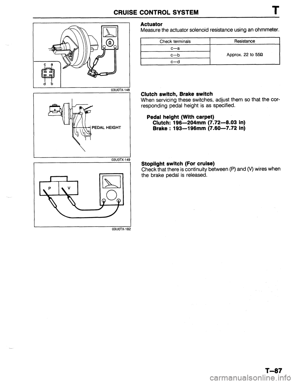
Actuator
Measure the actuator solenoid resistance using an ohmmeter.
Check terminals
c-a
c-b Resistance
Approx. 22 to 553
Clutch switch, Brake switch
When servicing these switches, adjust them so that the cor-
responding pedal height is as specified.
Pedal height (With carpet)
Clutch: 196-204mm (7.72--6.03 in)
Brake : 193-196mm (7.60-7.72 in)
Stoplight switch (For cruise)
Check that there is continuity between (P) and (V) wires when
the brake pedal is released.
T-87
Page 1034 of 1164

TD TECHNICAL DATA
Coil Spring Specifications (See page R-5 for coil spring applications)
*’ Main identification mark color: Indicated on second coil from bottom. l * Auxiliary identification mark color: Indicated on third coil from bottom.
T. BODY ELECTRICAL SYSTEM
Item
Headlight
Frnnt tl wn sinnnl/Pnrkinn linht
Specification (W) (Bulb Trade number)
65145 (9004)
2718 II I 571
I
“‘VW, I u”“y’ 1. I” \’ ‘V’,
uinh mount stoplight 18.4 (1141)
turn single light 27 (1156)
Y-,-~p light 27 (1156)
Rear side marker light (Sedan) 3.8 (194)
License plate light 7.5 (89) [PROTEGE], 5 (168) [3HBl
Interior 10
Interior and spot lamp
spot 6
Interior lamp 10
‘i--” Spot lamp (in overhead console)
8 (67)
Cargo room lamp 5 (168)
Trunk room lamp 5 (168)
I I
ntminr Iamnc
I
Curtesy lamp
High beam
Turn light
Brake
Hold
) Charge 5 (168)
3.4
3.4
3
3 (158)
i
Oil pressure
Washer
Seat belt
Malfunction
Fuel
illumination 3 (158)
3 (158)
3 (158)
3 (158)
3 (158)
3 (158)
3.4 Indicator and
warning lamps
Check 3 (158)
Dif. lock
I 3 (158) .-
,
-.-’
I
I
TD-20