coolant level MAZDA PROTEGE 1992 User Guide
[x] Cancel search | Manufacturer: MAZDA, Model Year: 1992, Model line: PROTEGE, Model: MAZDA PROTEGE 1992Pages: 1164, PDF Size: 81.9 MB
Page 252 of 1164

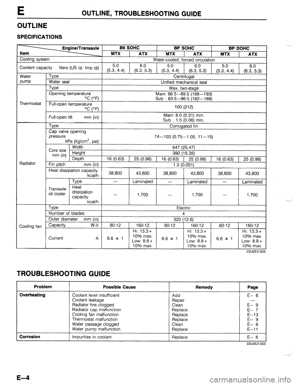
E OUTLINE, TROUBLESHOOTING GUIDE
OUTLINE
SPECIFICATIONS
B6 SOHC
BP SOHC BP DOHC
MTX
1 ATX 1 MTX ATX 1 MTX
ATX
Cooling system
Water-cooled, forced circulation
Coolant capacity liters (US qt, Imp qt) 5.0 6.0
5.0
(5.3, 4.4) (6.3, 5.3)
(5.35.04.4) (6.zi.3) (5.3, 4.4) (6.::.3)
Water
pump
Thermostat
Radiator
Cooling fan
L Type
Water seal Centrifugal
Unified mechanical seal
Type Opening temperature
‘C (OF’) Wax, two-stage
Main: 86.5-89.5 (188-193)
Sub : 83.5-86.5 (182-188)
Full-open temperature
OC (OF)
Full-open lift mm (in)
Type
Cap valve opening
pressure 100 (212)
Main: 8.0 (0.31) min.
Sub : 1.5 (0.06) min.
Corrugated fin
74-103 (0.75-1.05, 11-15)
kPa (kg/cm2, psi)
Width
Core size Height
mm (in)
Depth
Fin pitch
mm (in) 647 (25.47)
390 (15.35)
16 (0.63) 1 25 (0.98) 1 16 (0.63) 1 25 (0.98) 1 16 (0.63) 1 25 (0.98)
1.3 (0.051)
Heat dissipation capacity
kcallh 1 38,800 [ 43,800 ( 38,800 1 43,800 1 38,800 1 43,800 1
Type
Transaxle Heat
oil cooler dissipation
capacity
kcallh
Tvoe
- Laminated - Laminated -
Laminated
1,700
I .I -?nn
- -
I,,“”
I
I - I 4 Ye,-. I,IVV 1
, a-
- Electric
Number of blades 4
Outer diameter mm (in)
320 (12.6)
Capacity w-v 80-12 1 160-12 ) 80-12 ) 160-12 1 80-12 1 160-12
1 Hi: 13.3+ 1 1 Hi: 13.3+ 1 1 Hi: 13.3+
Current
TROUBLESHOOTING GUIDE I I I I
Problem Possible Cause
Overheating
Coolant level insufficient
Coolant leakage
Radiator fins clogged
Radiator cap malfunction
Cooling fan malfunction
Thermostat malfunction
Water passage clogged
Water puma malfunction .- Remedy Page
Add
Repair
Clean
Replace
Replace
Replace
Clean
Reolace E- 6
E-9
E- 7
E-13
E- 9
E- 6
E-11
I Corrosion
1 Impurities in coolant 1 Replace
I E-6 I
03UOEX-005
Page 253 of 1164

ENGINE COOLANT E
ENGINE COOLANT
PREPARATION
SST
49 9200 145
For 49 9200 146
For
inspection of inspection of
cooling system Adapter A cooling system
pressure (Part of pressure
49 9200 145)
05UOEX-00
INSPECTION
Warning
l Never remove the radiator cap while the engine is
hot.
l Wrap a thick cloth around the cap when removing it.
l When removing the radiator cap, loosen it slowly
to the first stop until the pressure in the radiator is
released, and then remove it.
03UOEX~006
Coolant Level (Engine cold)
1. Verify that the coolant level is near the radiator filler neck.
2. Remove the coolant level gauge and check the coolant level.
Coolant Quality
1. Verify that there is no buildup of rust or scale around the
radiator cap or radiator filler neck.
2. Verify that coolant is free of oil. Replace the coolant if
necessary.
Coolant Leakage
1. Connect a radiator tester (commercially available) and the
SST to the radiator filler neck.
2. Apply
103 kPa (1.05 kg/cm2, 15 psi) pressure to the
system.
3. Verify that the pressure is held.
If not, check for coolant leakage.
E-5
Page 344 of 1164

F ENGINE TUNE-UP
ENGINE TUNE-UP
PREPARATlON
SST
I
I I
49 BO19 9AO
System Selector For
inspection of igni-
tion timing and
idle speed
hA ‘I
03UOFX-04
03UOFX-04
03UOFX-04
NG POINT
03UOFX-04 03UOFX-045
BASIC INSPECTION
Engine Oil
1. Remove the engine oil level gauge and check the engine
oil level and oil condition.
2. Add or change the oil as necessary.
Coolant
Warning
l Never remove the radiator cap while the engine is
hot.
l Wrap a thick cloth around the cap before carefully
removing it.
1. Remove the coolant level gauge from the coolant reservoir.
2. Check that the coolant level is between the L and F marks
of the gauge.
3. Add coolant if necessary.
Battery
1. Check for corrosion on the terminals and for loose cable
connections. If necessary, clean the clamps and tighten
them firmly.
2. Check that the electrolyte level is between the UPPER LEV-
EL and LOWER LEVEL marks.
3. Add distilled water if necessary.
4. Check the specific gravity with a hydrometer.
Gravity: 1.27-l .29 (at 20% [68OF] )
Page 710 of 1164

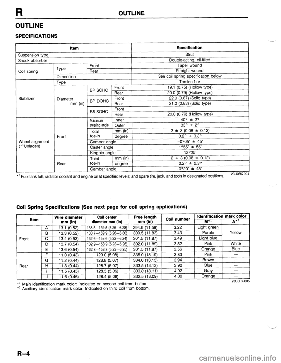
R OUTLINE
OUTLINE
SPECIFICATIONS
Suspension type Item Specification Strut
Shock absorber Double-acting, oil-filled
Coil spring
Stabilizer Type Front Taper wound
Rear Straight wound
Dimension See coil spring specification below
Type Torsion bar
BP SOHC Front 19.1 (0.75) (Hollow type)
Rear 20.0 (0.79) (Hollow type)
Diameter 22.0 (0.87) (Solid type)
mm (in) BP DOHC ;eTrt
21 .O (0.83) (Solid type)
P ,
-
66 SOHC rronr
Rear 20.0 (0.79) (Hollow type)
Maximum Inner 400 f 20
steering angle
Outer 330 f 20
Total mm (in) 2 f 3 (0.08 f 0.12)
Front toe-in
degree 0.2O f 0.3O
Wheel alignment
(*‘Unladen) Camber angle -0005’ f 45’
Caster angle 1055 * 55’
Kingpin angle 12O25’
Total mm (in) 2 f 3 (0.08 * 0.12)
Rear toe-in
degree 0.2O f 0.3O
Camber angle -0°20’ f 45’
*’ Fuel tank full; radiator coolant and engine oil at specified levels; and spare tire, jack, and tools in designated positions.
23UORX.004
Coil Spring Specifications (See next page for coil spring applications)
I Item Wire diameter Coil center Free lel.=-. .
mm iin1 rliamotor mm [in mm (in 1 coil numbs
Front
nath
1 _ . . *St Identification mark color +l
., . . . . I...,
-*.....-.“, * . . . . . ,..-, -....- I--‘, M iA*=
A 13.1 (0.52) 133.5-159.5 (5.26-6.28)
294.5 (11.59) 3.22 Light green
B 13.3 (0.52) 133.7-159.9 (5.26-6.30) 300.5 (11.83)
3.43 Purple Yellow
C 13.4 (0.53)
132.6-158.6 (5.22-6.24) 301.5 (11.87) 3.49
Light blue
D 13.7 (0.54)
132.9-158.9 (5.23-6.26) 302.0 (11.89) 3.52
Pink White
I F I 12f3 Kl5Al I 1.17 A-l!% 8 f!i PR-Fi 751
I RrIl .5 II 1 6x71 I 3.56 Orange
Blue
3 83 Pink -
Brown - .“._ \“.- .,
. “W.., ~ - -. - \-. -- -. - -, -- .-
\’ .‘-‘I t
F 11 .o (0.43) 129.0 (5.08)
335.0 (13.19) -.--
G 11.2 (0.44) 128.8 (5.07)
334.0 (13.15) 3.94
Rnnr l-4
1 I ? 07 AA 1387 /5n7
.?m !i 113 1% 3 an Blue - I I I I .” \v.-7, I&V., \V.“., ---.., \.-. .-, I 11.5 (0.45) 128.5 (5.06)
333.0 (13.11) i:oi Gray
-
J 11.6 (0.46) 128.4 (5.06)
332.5 (13.09) 4.00 Orange
-
l ’ Main identification mark color: Indicated on second coil from bottom.
*’ Auxiliary identification mark color: Indicated on third coil from bottom. 23UORX-005
R-4
Page 713 of 1164

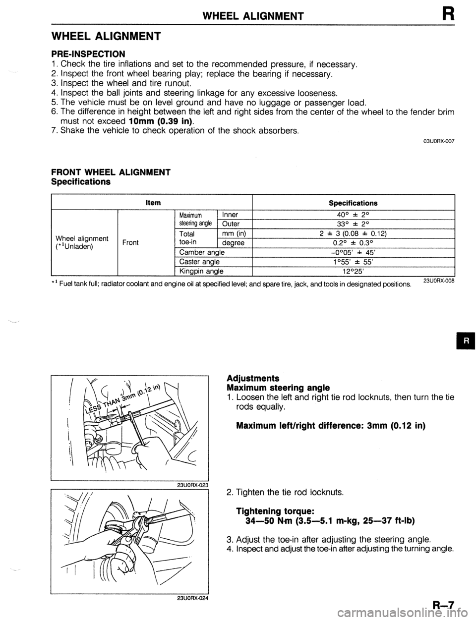
WHEEL ALIGNMENT
WHEEL ALIGNMENT
PRE-INSPECTION
1. Check the tire inflations and set to the recommended pressure, if necessary.
2. Inspect the front wheel bearing play; replace the bearing if necessary.
3. inspect the wheel and tire runout.
4. Inspect the ball joints and steering linkage for any excessive looseness.
5. The vehicle must be on level ground and have no luggage or passenger load.
6. The difference in height between the left and right sides from the center of the wheel to the fender brim
must not exceed
10mm (0.39 in).
7. Shake the vehicle to check operation of the shock absorbers.
03UORX.007
FRONT WHEEL ALIGNMENT
Specifications
item
Specifications
Maximum Inner 4o” f: 2O
steering angle Outer
33O f 2O
Total mm (in) 2 f 3 (0.08 f 0.12)
toe-in dearee 0.20 f 0.30 Wheel alignment
(*‘Unladen) Front
*I Fuel tank full; radiator coolant and Camber angle -0005 * 45’
Caster angle 1°55’ f 55’
Kingpin angle 12O25’
engine oil at specified level; and spare tire, jack, and tools in designated positions.
23UORX-008
I
I 23UORX-023
Adjustments
Maximum steering angle
1. Loosen the left and right tie rod locknuts, then turn the tie
rods equally.
Maximum left/right difference: 3mm (0.12 in)
2. Tighten the tie rod locknuts.
Tightening torque:
34-50 N-m (3.5-5.1 m-kg, 25-37 ft-lb)
3. Adjust the toe-in after adjusting the steering angle.
4. Inspect and adjust the toe-in after adjusting the turning angle.
I 23UORX-024
R-7
Page 715 of 1164

WHEEL ALIGNMENT
REAR WHEEL ALIGNMENT
Specifications
kern Specifications
Total mm (in) 2 f 3 (0.08 f 0.12)
Wheel alignment
(*‘Unladen) Rear toe-in
degree 0.2O f 0.3O
Camber angle -0020’ f 45’
*I Fuel tank full; radiator coolant and engine oil at specified level; and spare tire, jack, and tools in designated positions.
13UORX-012
Adjustment
Total toe-in
1. Loosen the lateral link locknuts.
2. Turn the lateral link adjustment link to adjust.
Note
l One turn of the link changes 11.3mm (0.44 in).
3. Tighten the lateral link locknuts to the specified torque.
Tightening torque:
55-64 N,m (5.6-6.5 m-kg, 41-47 ft-lb)
R-9
Page 1033 of 1164

TECHNICAL DATA
Q. WHEELS AND TIRES
Item Specifications
Wheel
Size
Off set Standard: 13x5-J, 14x5 l/2-JJ
Temporary
mm (in) 1 _ spare: 14x4-T
45 (1.77)
I Diameter of oitch circle
mm (in) I 100 (3.94)
r I Pl
-
Inflation pressure kPa (kg/cm*, psi) Front 1 8
I 9
Runout limit
Unbalance limit mm (in) ;lii.raltLa’
a (02) ’
13 inch wheel: 11 (0.
R. SUSPENSION Item Specifications
Suspension type Strut
)e Double-acting, oil-filled
I Shock absorber tyf
Coil spring
Type
Dimension
Type Front Taper wound
Rear Straight wound
See next page
Torsion bar
I
I C.rrn,
19.1 (0.75)
20.0 (0.79)
22.0 (0.87)
21 .O f0.83)
Wheel alignment
(“‘Unladened) BP SOHC ;;a;
Diameter
mm (in) BP DOHC - ;la;t
Front -
B6 SOHC
Rear 20.0 (0.79)
Maximum Inner 4o” f 2O
steering angle Outer
Total mm (in) 2 f 3 (0.08 j
Front toe-in
dearee
.-.._
Rear
.--. I --- ~~
Camber angle
Caster angle
Kingpin angle
I Total
I mm OnI I I toe-in
1 dearee I , --U’-- 1
Camber angle
I 33O * 2O
: 0.12)
0.2O f 0.3O
-0OO5’ * 45’
1055’ * 55’
12O25’
2 f 3 (0.08 f 0.12)
0.2O f 0.3O
-0°20’ f 45’
l ’ Fuel tank full; radiator coolant and engine ail at specified level; and spare tire, jack, and tools in designated posmons.
TD-19