warning MAZDA PROTEGE 1992 User Guide
[x] Cancel search | Manufacturer: MAZDA, Model Year: 1992, Model line: PROTEGE, Model: MAZDA PROTEGE 1992Pages: 1164, PDF Size: 81.9 MB
Page 137 of 1164

ENGINE TUNE-UP PROCEDURE 82
ENGINE TUNE-UP PROCEDURE
PREPARATION
SST
49 BO19 9AO
drive belt tension
23UOB2-048
OBUOBX-158
I’ ,
OSJOBX-001
V BELT
V RIBBED BELT
_
x 0 x
3
L
03UOB2-005
ENGINE OIL
Inspection
1. Be sure the vehicle is on level ground.
2. Warm up the engine to normal operating temperature and
stop it.
3. Wait for 5 minutes.
4. Remove the oil level gauge and check the oil level and con-
dition.
5. Add or replace oil if necessary.
Note
l The distance between the L and F marks on the level
gauge represents 0.8 liter (0.85 US qt, 0.70 Imp qt).
ENGINE COOLANT
Inspection
Coolant level (engine cold)
Warning
l Never remove the radiator cap while the engine is
hot.
l Wrap a thick cloth around the cap when removing it.
1. Verify that the coolant level is near the radiator filler neck.
2. Remove the coolant level gauge and check the coolant level.
3. Add coolant if necessary.
Coolant quality
1. Verify that there is no buildup of rust or scale around the
radiator cap or radiator filler neck.
2. Verify that the coolant is free of oil.
3. Replace the coolant if necessary.
DRIVE BELT
Inspection
1. Check the drive belts for wear, cracks, and fraying. Replace
if necessary.
2. Verify that the drive belts are correctly mounted on the
pulleys.
B2-5
Page 148 of 1164

82 ON-VEHICLE MAINTENANCE
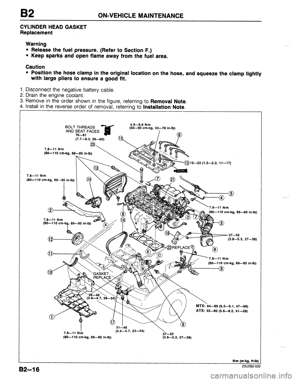
CYLINDER HEAD GASKET
Replacement
Warning
l Release the fuel pressure. (Refer to Section F.)
l Keep sparks and open flame away from the fuel area.
Caution
l Position the hose clamp in the original location on the hose, and squeeze the clamp lightly
with large pliers to ensure a good fit.
1. Disconnect the negative battery cable.
2. Drain the engine coolant.
3. Remove in the order shown in the figure, referring to
Removal Note.
4. install in the reverse order of removal, referrina to Installation Note.
BOLT THREADS ?&d 4.9-8.8 N.m
fsn-an om.h 41-‘71( ir
AND SEAT FACES ,-- -- -... ..=, _” . _ ..I-lb)
78-81 - /
(7.7-8.3, 58-60)
7.8-11 N.m
(80-l 10 cm-ka, 69-95
, . . . . . . (80-l 10 cm-kg, 69-9: in-lb) (j-$15-23 (1.5-2.3, 11-17)
82-l 6
7.8-11 N.m
(80-110 cm-k?, 69-95 In-lb) 180-110 cm-ka. 69-95 in-lb
-37-52
(3.8-5.3, 27-38)
’
nl MTX:?64-69 (6.6-9.1,
PTX: 55-60 (6.6-8.2, 69-95 in. .Ib)
47-86)
41-69)
7.8-11 N./n (3.2-4.7, 23-34)
37-52
(80-110 cm-kg, 69-95 in-lb) (3.8-5.3, 27-38)
N-m (m-kg, N-lb)
^^. .^_^ __
Page 163 of 1164

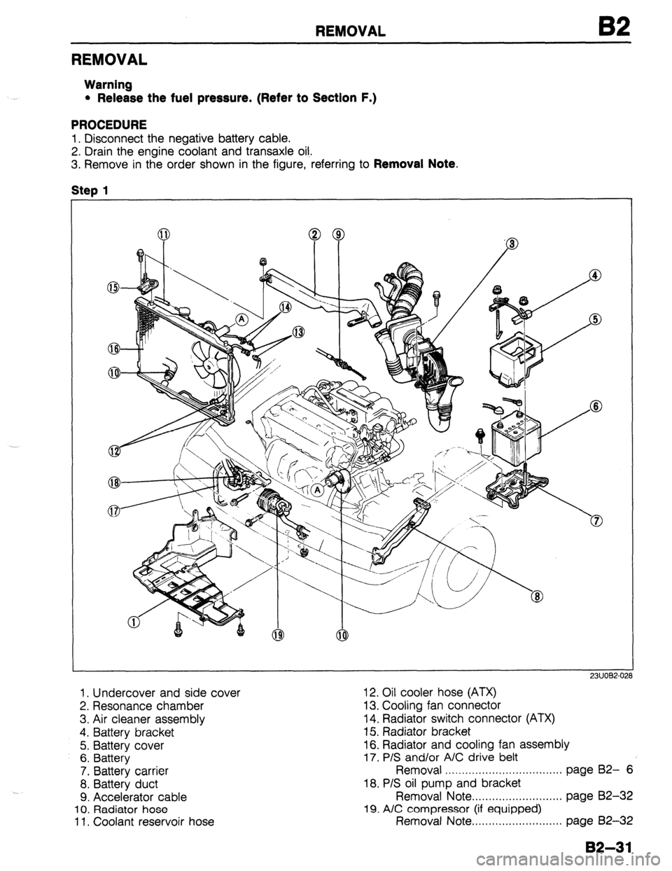
REMOVAL
REMOVAL
Warning
l Release the fuel pressure. (Refer to Section F.)
PROCEDURE
1. Disconnect the negative battery cable.
2. Drain the engine coolant and transaxle oil,.
3. Remove in the order shown in the figure, referring to
Removal Note.
Step
1
1. Undercover and side cover 12. Oil cooler hose (ATX)
2. Resonance chamber 13. Cooling fan connector
3. Air cleaner assembly 14. Radiator switch connector (ATX)
4. Battery bracket 15. Radiator bracket
5. Battery cover 16. Radiator and cooling fan assembly
6. Battery
17. P/S and/or A/C drive belt
7. Battery carrier Removal . . . . . . . . . . . . . . . . . . . . . . . . . . . . . . . . . . . page B2- 6
8. Battery duct 18. P/S oil pump and bracket
9. Accelerator cable Removal Note . . . . . . . . . . . . . . . . . . . . + . . . . . . page 82-32
10. Radiator hose 19. A/C compressor (if equipped)
11. Coolant reservoir hose Removal Note.. . . . . . . . . . . . . . . . . . . . . . . . . . page 82-32
B2-31
Page 165 of 1164

REMOVAL
Step 3
1. Disconnect the hoses shown in the figure.
J”“DC-” I I
1. Fuel hose
3. Brake vacuum hose
Removal
Note . . . . . . . . . . . . . . . . . . . . . . . . . . . . . . . . . . . . .
below
4. Vacuum hose (Purge control)
2. Heater hose
Removal Note . . . . . . . . . . . . . , . . . . . . . . . . . .
05UOBX-078
0311082-052
. . . . .
below 5. Vacuum hose (Cruise control)
Removal note
Fuel hose
Warning
l Keep sparks and open flame away from the fuel
area.
Caution
l Cover the hose with a rag because fuel will spray
out when disconnecting.
l Plug the disconnected hoses to avoid fuel leakage.
1. Disconnect the fuel hoses.
Heater hose
Caution
l Heater hose joint has O-rings and spacer.
l Do not lose them when removing.
1. Push the heater hose retainer and remove the heater hose.
82-33
Page 227 of 1164

INSTALLATION B2
Step 2
Warning
l Be sure the vehicle is securely supported on Safety stands.
Torque Specifications
‘4-l 03
‘.5-10.5, 54-76)
37-52 (3.8-5.3, 27-38)
/
37-52 (3.8-5.3, 27-38)
64-89 (6.5-9.1, 47-66) 64-89 (6.5-9.1, 47-66)
N.m (m-kg, ft-II
OWOBX-21
Engine mount member (ATX)
1. Install the engine mount member.
Tightening torque:
64-89 N*m (6.5-9.1 m-kg, 47-66 ft-lb)
I I 03UOB2-130 1132-95
Page 241 of 1164

ENGINE OIL, OIL FILTER D
b
I
03UODX-00
ONODX-01
r
03UODX-011
ENGINE OIL
INSPECTION
1. Be sure the vehicle is on level ground.
2. Warm up the engine to normal operating temperature and
stop it.
3. Wait for five minutes.
4. Remove the oil level gauge and check the oil level and con-
dition.
5. Add or replace oil as necessary.
Note
l The distance between the L and F marks on the level
gauge represents 0.8 liter (0.85 US qt, 0.70 Imp qt).
REPLACEMENT
Warning
l Be careful when draining; the oil is hot.
1. Warm up the engine to normal operating temperature and
stop it.
2. Remove the oil filler cap and the oil pan drain plug.
3. Drain the oil into a suitable container.
4. Install a new gasket and the drain plug.
Tightening torque:
29-41 N,m (3.0-4.2 m-kg, 22-30 ft-lb)
5. Refill the engine with the specified type and amount of en-
gine oil.
6. Refit the oil filler cap.
7. Run the engine and check for leaks.
8. Check the oil level and add oil if necessary.
Oil pan capacity
B6 SOHC
BP SOHC and DOHC
liters (US qt, Imp qt)
3.0 (3.2, 2.6)
3.6G.843.2)
w
03UODX-011
D-7
Page 253 of 1164

ENGINE COOLANT E
ENGINE COOLANT
PREPARATION
SST
49 9200 145
For 49 9200 146
For
inspection of inspection of
cooling system Adapter A cooling system
pressure (Part of pressure
49 9200 145)
05UOEX-00
INSPECTION
Warning
l Never remove the radiator cap while the engine is
hot.
l Wrap a thick cloth around the cap when removing it.
l When removing the radiator cap, loosen it slowly
to the first stop until the pressure in the radiator is
released, and then remove it.
03UOEX~006
Coolant Level (Engine cold)
1. Verify that the coolant level is near the radiator filler neck.
2. Remove the coolant level gauge and check the coolant level.
Coolant Quality
1. Verify that there is no buildup of rust or scale around the
radiator cap or radiator filler neck.
2. Verify that coolant is free of oil. Replace the coolant if
necessary.
Coolant Leakage
1. Connect a radiator tester (commercially available) and the
SST to the radiator filler neck.
2. Apply
103 kPa (1.05 kg/cm2, 15 psi) pressure to the
system.
3. Verify that the pressure is held.
If not, check for coolant leakage.
E-5
Page 254 of 1164

E ENGINE COOLANT
SPECIFIC
GRAVITY COOLANT PROTECTION
l.OOd ’ ’ I I I I I
0, I I
-10 0 i 10 20 30 40 50 60
70 60 90
(14) (32) (50) (66) (66)(104)(122)(140)(158~176)(194)
COOLANT TEMPERATURE OC (OF)
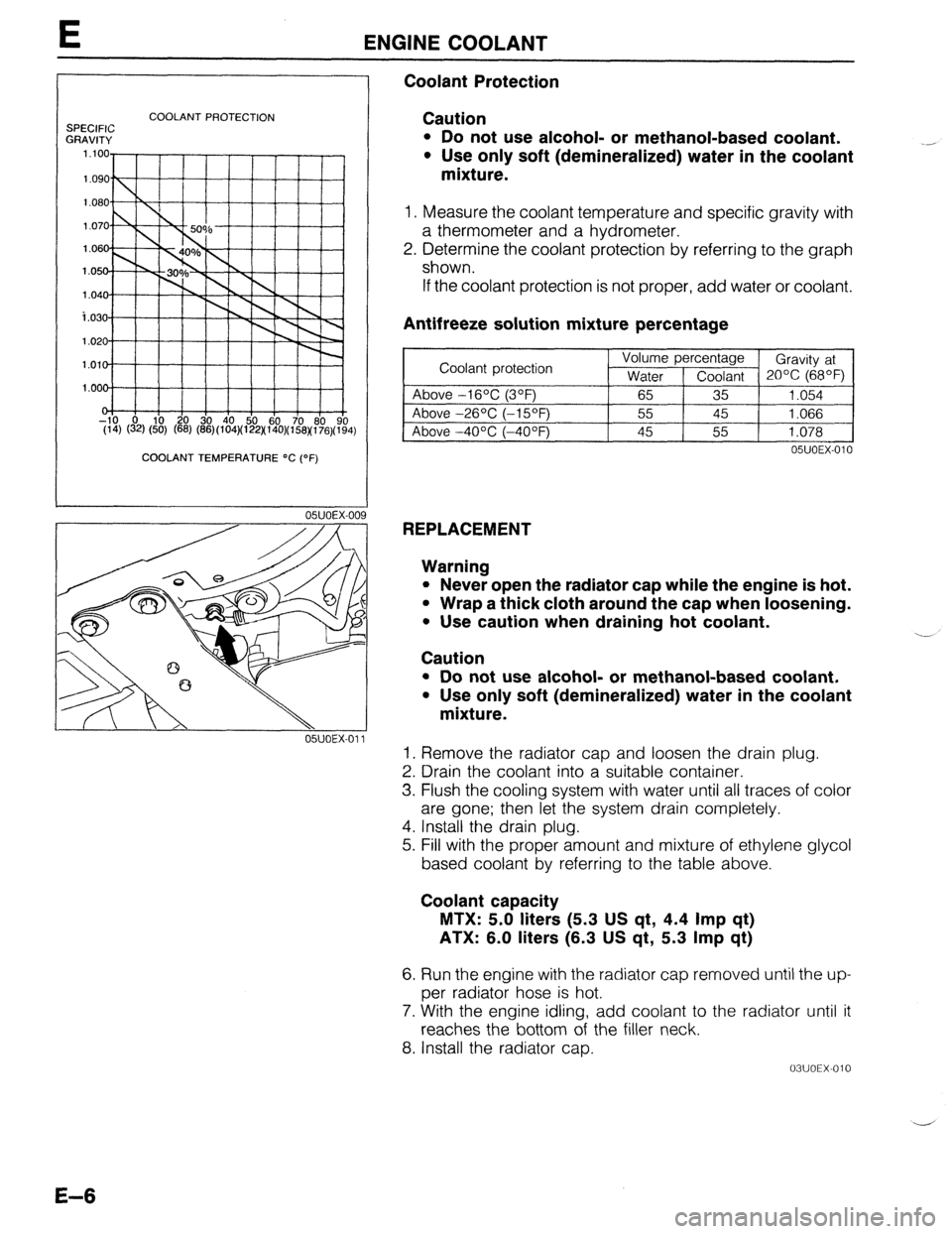
Coolant Protection
Caution
l Do not use alcohol- or methanol-based coolant.
l Use only soft (demineralized) water in the coolant
mixture.
1. Measure the coolant temperature and specific gravity with
a thermometer and a hydrometer.
2. Determine the coolant protection by referring to the graph
shown.
If the coolant protection is not proper, add water or coolant.
Antifreeze solution mixture percentage
~1
05UOEX-010
REPLACEMENT
Warning
l Never open the radiator cap while the engine is hot.
l Wrap a thick cloth around the cap when loosening.
. Use caution when draining hot coolant.
Caution ..-
l Do not use alcohol- or methanol-based coolant.
l Use only soft (demineralized) water in the coolant
mixture.
1. Remove the radiator cap and loosen the drain plug.
2. Drain the coolant into a suitable container.
3. Flush the cooling system with water until all traces of color
are gone; then let the system drain completely.
4. Install the drain plug.
5. Fill with the proper amount and mixture of ethylene glycol
based coolant by referring to the table above.
Coolant capacity
MTX: 5.0 liters (5.3 US qt, 4.4 Imp qt)
ATX: 6.0 liters (6.3 US qt, 5.3 Imp qt)
6. Run the engine with the radiator cap removed until the up-
per radiator hose is hot.
7. With the engine idling, add coolant to the radiator until it
reaches the bottom of the filler neck.
8. Install the radiator cap.
03UOEX-010 -
E-6
Page 265 of 1164

RADIATOR THERMOSWITCH E
RADIATOR THERMOSWITCH
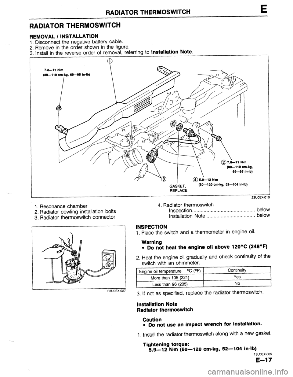
REMOVAL / INSTALLATION
1. Disconnect the negative battery cable.
2. Remove in the order shown in the figure.
3. Install in the reverse order of removal. referrina to
Installation Note.
(80-110 cm-kg,
69-95 in-lb)
GAdKET,
REPLACE (60-120 cm-kg, 52-104 In-lb)
1. Resonance chamber
2. Radiator cowling installation bolts
3. Radiator thermoswitch connector 4. Radiator thermoswitch
Inspection . . . . . . . . . . . . . . . ..*...,..,..................* below
Installation Note ..,.,........,.......,........,... below
1. Place the switch and a thermometer in engine oil.
03UOEX-02
INSPECTION
Warning
l Do not heat the engine oil above 120°C (248OF)
2. Heat the engine oil gradually and check continuity of the
switch with an ohmmeter.
Engine oil temperature OC (OF) Continuity
More than 105 (221)
Yes
Less than 96 (205) No
3. If not as specified, replace the radiator thermoswitch.
lnstallatlon Note
Radiator thermoswitch
Caution
l Do not use an impact wrench for installation.
1. Install the radiator thermoswitch along with a new gasket.
Tightening torque:
5.9-12 N#m (60-l 20 cm-kg, 52-104 in-lb)
13UOEX-005
E-17
Page 343 of 1164
![MAZDA PROTEGE 1992 User Guide TROUBLESHOOTING GUIDE
27 MIL ALWAYS ON
DESCRIP- *Self-Diagnosis Checker does not indicate Malfunction Code No. but MIL always ON
TION
[TROUBLESHOOTING HINTS]
*Short circuit in wiring harness
l E MAZDA PROTEGE 1992 User Guide TROUBLESHOOTING GUIDE
27 MIL ALWAYS ON
DESCRIP- *Self-Diagnosis Checker does not indicate Malfunction Code No. but MIL always ON
TION
[TROUBLESHOOTING HINTS]
*Short circuit in wiring harness
l E](/img/28/57077/w960_57077-342.png)
TROUBLESHOOTING GUIDE
27 MIL ALWAYS ON
DESCRIP- *Self-Diagnosis Checker does not indicate Malfunction Code No. but MIL always ON
TION
[TROUBLESHOOTING HINTS]
*Short circuit in wiring harness
l ECU malfunction
iTEF 1
1
-
s
Disconnect (Y/B) wire from ECU and check if
MIL goes off
‘YIB
ATX YIB
INSPECTION ACTION
Yes Replace ECU CT page F-149
No Check for short circuit in wiring be-
tween instrument cluster and ECU
23UOFX-042
28
MIL NEVER ON
IESCRIP- *Self-Diagnosis Checker indicates Malfunction Code No. of input device but MIL never ON
RON *Other indicator and warning lamps OK
:TROUBLESHOOTING HINTS]
b Bulb burned
‘Open circuit in wiring harness
m ECU malfunction
TEP INSPECTION
ACTION
1 Ground (Y/B) wire at ECU with jumper wire and
Yes Check connection of ECU connector
check if MIL comes on
MTX e If OK, replace ECU w page F-149
I- i -!~ !r--~r’:~;-‘;- --~_:- ,
1 i r 1 1 1 ;-.:,~;~$~& {-;&# ,$&]j 4 If not OK, repair ECU connector
! No
Check if bulb is OK
ATX 13 If OK, repair (Y/B) wire between
ECU and instrument cluster
e If not OK, replace bulb CT page T-83
23UOFX-043
29 A/C DOES NOT WORK
DESCRIP- *Blower fan operates but magnet clutch does not operate
TION
[TROUBLESHOOTING HINTS]
*Open or short circuit in wiring harness
*A/C relay, A/C switch, or magnetic clutch malfunction
l ECU malfunction
TEP/ INSPECTION ACTION
1 1 Check ECU
terminal 10 (MTX) 10 (ATX) voltage 1
Yes Check ECU terminal 1 J (MTX) 1 L (ATX)
OK
CT= page F-152
MTX
T7J++!;i”-
L
ATX
No voltage OK
CT page F-152
1-3 If OK, check A/C system
c3- page U-30
~3 If not OK, replace ECU CT page F-149
Check for cause w page F-153
F-77