warning MAZDA PROTEGE 1992 Owner's Guide
[x] Cancel search | Manufacturer: MAZDA, Model Year: 1992, Model line: PROTEGE, Model: MAZDA PROTEGE 1992Pages: 1164, PDF Size: 81.9 MB
Page 397 of 1164

231JOFX-1
FUEL SYSTEM F
INJECTOR
Inspection
Operation check
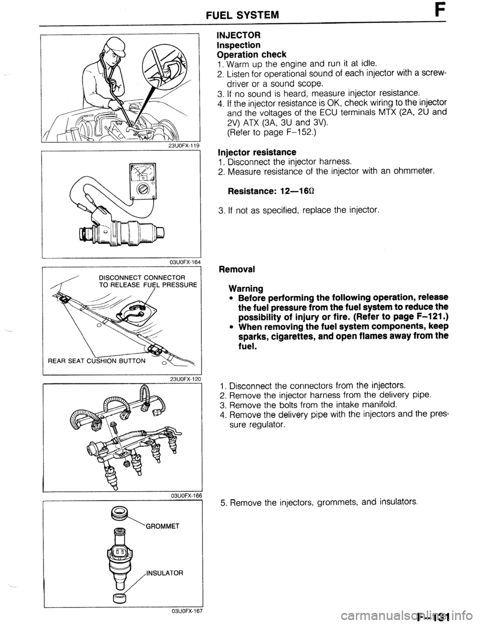
1. Warm up the engine and run it at idle.
2. Listen for operational sound of each injector with a screw-
driver or a sound scope.
3. If no sound is heard, measure injector resistance.
4. If the injector resistance is OK, check wiring to the injector
and the voltages of the ECU terminals MTX (2A, 2U and
2V) ATX (3A, 3U and 3V).
(Refer to page F-152.)
Injector resistance
1. Disconnect the injector harness.
2. Measure resistance of the injector with an ohmmeter.
Resistance: 12-l 6Q
3. If not as specified, replace the injector.
03UOFX-1
DISCONNECT CONNECTOR
TO RELEASE FU5L PRESSUR
REAR SEAT C
23UOFX-1
OBUOFX-
GRQMMET
INSULATOR
c5
OSUOFX-
Removal
Warning
l Before performing the following operation, release
the fuel pressure from the fuel system to reduce the
possibility of injury or fire. (Refer to page F-121 .)
l When removing the fuel system components, keep
sparks, cigarettes, and open flames away from the
fuel.
1. Disconnect the connectors from the injectors.
2. Remove the injector harness from the delivery pipe.
3. Remove the bolts from the intake manifold.
4. Remove the delivery pipe with the injectors and the pres-
sure regulator.
5. Remove the injectors, grommets, and insulators.
F-131
Page 398 of 1164

l Be extremely careful when working with fuel. I
23UOFX.121 Always work away from sparks or open flames.
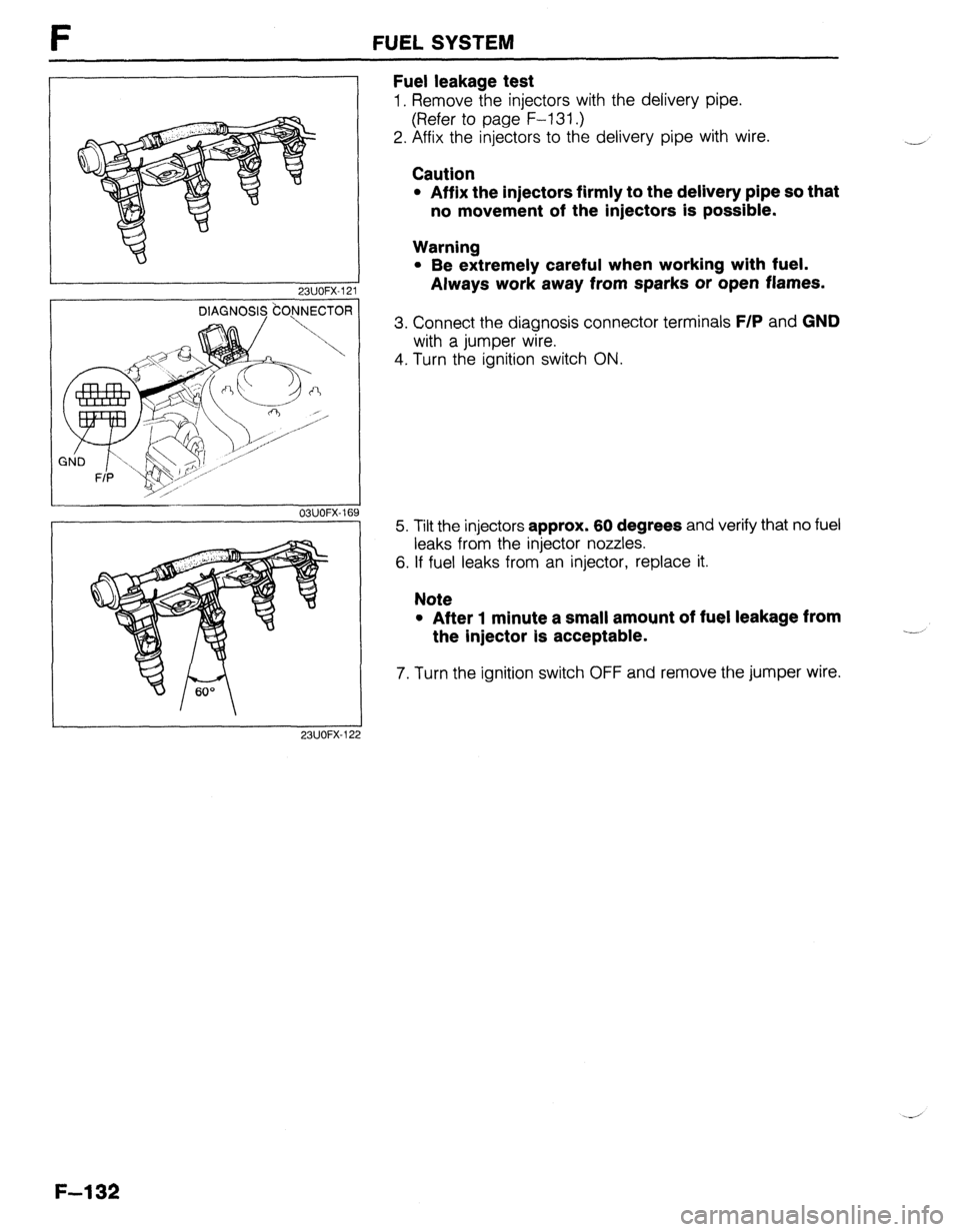
3. Connect the diagnosis connector terminals F/P and GND
with a jumper wire.
FUEL SYSTEM
Fuel leakage test
1. Remove the injectors with the delivery pipe.
(Refer to page F-l 31.)
2. Affix the injectors to the delivery pipe with wire.
Caution
l Affix the injectors firmly to the delivery pipe so that
no movement of the injectors is possible.
-
Warning
4. Turn the ignition switch ON.
03UOFX-16’
23UOFX-12 9 5. Tilt the injectors approx. 60 degrees and verify that no fuel
leaks from the injector nozzles.
6. If fuel leaks from an injector, replace it.
Note
l After 1 minute a small amount of fuel leakage from
the injector Is acceptable.
7. Turn the ignition switch OFF and remove the jumper wire.
-i
F-l 32
Page 409 of 1164

FUEL CUT CONTROL SYSTEM F
FUEL CUT CONTROL SYSTEM
DESCRIPTION
This system is used to improve the fuel economy, to prevent engine bucking during deceleration, and to
protect the engine from overspeeding.
23UOFX-127
PREPARATION
SST
r
49 9200 162
03UOFX.191
l7=---T II USE CPNNECTOR A
03UOFX-19
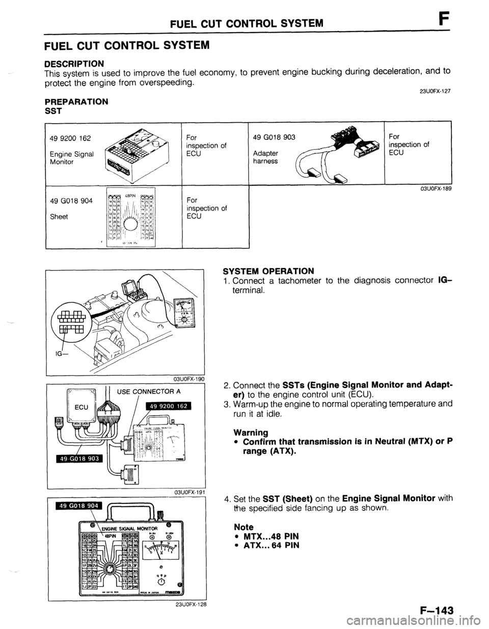
SYSTEM OPERATION
1. Connect a tachometer to the diagnosis connector IG-
terminal.
2. Connect the
SSTs (Engine Signal Monitor and Adapt-
er)
to the engine control unit (ECU).
3. Warm-up the engine to normal operating temperature and
run it at idle.
Warning
l Confirm that transmission is in Neutral (MTX) or P
range (ATX).
4.
Set the SST (Sheet) on the Engine Signal Monitor with
the specified side fancing up as shown.
Note
l MTX...48 PIN
l ATX...64 PIN
I 23UOFX-128
F-l 43
Page 444 of 1164

TROUBLESHOOTING GUIDE
TROUBLESHOOTING GUIDE
DIAGNOSTIC INDEX
No. Troubleshooting items
Page
1
Will not crank-starter motor does not operate G-4
2
Will not crank-starter motor spins G-4
3
Cranks slowly G-5 4
Alternator warning lamp illuminates when engine running
G-5
5 Discharged battery G-5
6
Misfire
G-5
03UOGX-004
SYMPTOM TROUBLESHOOTING -
1
iTEl
1
2
3 Will not crank-Starter motor does not operate
INSPECTION
T
Check if engine cranks with fully charged battery
Check if battery voltage is applied at B terminal
TERMINAL
battery voltaae is aoolied at S terminal
when clutch pedal depressed (MTX) and ignition
switch in START position
S TERMINAL
Yes
No
Yes ACTION Check charging system CT- page G-7
Go to next step
Go to next step
No Check wire harness
Yes
l Check magnetic switch l Check field coil l Check armature
No
l Check starter interlock switch (MTX) ccp: page G-31 l Check inhibitor switch (ATX) c=p Section K l Check ignition switch CI Section T l Check wire harness
1 L-T page G-28
CT- page G-29
CT- page G-29
23UOGX.001
03UOGX-006
G-4
Page 445 of 1164

TROUBLESHOOTING GUIDE G
3 Cranks slowly
STEP INSPECTION ACTION
1 Check if engine cranks normally with fully Yes Check charging system CT page G-7
charged battery
No Go to next step
2 Check starter cable connection for looseness Yes Repair or replace connection
and corrosion
OBUOGX-OC
I 1 4
.
Alternator warning lamp illuminates when engine running
STEP INSPECTION ACTION
1 Check for correct battery voltage at idle Yes Check wire harness between alternator L terminal and aI*
Specification: 14.1--14.7V ternator warning lamp
No Check charging system w page G-7
03UOGX-008
5 I Discharged battery I 1TEP INSPECTION
f Check charging system w page G-7 -
6
TEF
1
r
--
Yes
03UOGX-009
ACTION
Turn ignition switch ON and check dark current as shown
Dark current: Below 20mA
No Repair or replace parts as necessary 1
Misfire
INSPECTION
-
Disconnect high-tension lead from each spark
plug and check for strong blue spark while
cranking
, i
Yes
No T-
I
ACTION
- Check spark plug w page G-f8
~3 If OK, engine electrical system normal
~3 If not OK, clean or replace spark plug
Check ignition system ci’ page G-16
1 03UOGX-010
G-5
Page 446 of 1164

G CHARGING SYSTEM
03UOGX-011
CIRCUIT DIAGRAM
CHARGING SYSTEM
PREPARATION
SST
I I
49 9200 020
Tension gauge,
V-ribbed belt For
inspection of
drive belt tension
STATOR
1 DIODE TRIO
T l-f-l /
-I J
WARNING
t
I --.- I I I I 15A
e I
I I -L
-E-
I IC REGULATOR
0
-
BATTERY = IGNITION
SWITCH
03u0tix-012
The alternator has a self-diagnostic function to warn of the following
If a problem arises, the alternator warning lamp illuminates. problems in the charging system.
1. S terminal circtiit open
2. No voltage output
3. Field coil circuit open
4. B terminal circuit open
5. Voltage output too high
G-6
Page 447 of 1164

CHARGING SYSTEM G
TROUBLESHOOTING
INSPlhdN
ACTION
1
Check battery voltage Yes Go to next step Specification: Above 12.4V
No
Check battery ri-page G-8
2 Start engine and check if alternator warning
Yes Go to Step 4
lamp goes out
No Go to next step
3 Check if voltages at alternator terminals are Yes Check wire harness between battery and terminal B
3. Turn all electrical loads ON and depress
2,500-3,000 rpm
l Do not ground terminal B
G-7
Page 449 of 1164

CHARGING SYSTEM G
RUB
PRO
03UOGX-01
Terminal and cable
1. Check the tightness of the terminals to ensure good electri-
cal connections.
2. Check for corroded or frayed battery cables.
3. Check the rubber protector on the positive terminal for prop-
er coverage.
4. Clean the terminals if necessary, and coat them with grease.
Recharging
Battery
55D23L Slow charge Quick charge
(A) (4
Under 6 Max. 20
Slow charging
It is not necessary to remove the vent caps to perform a slow
charge.
Quick charging
Remove the battery from the vehicle and remove the vent caps
to perform a quick charge.
Warning
l Before performing maintenance or recharging the
battery, turn off all accessories and stop the engine.
l The negative cable must be removed first and in-
stalled last.
l Set the battery in water when quick charging to pre-
vent overheating the battery.
G-9
Page 699 of 1164

PARKING BRAKE SYSTEM
PARKING BRAKE LEVER
Removal / Inspection / Installation
Caution
l Install the parking brake switch so that it contacts the parking brake lever when the lever is
fully released.
l Turn the ignition switch ON, and check that the parking brake warning lamp illuminates with
the lever pulled one notch.
1. Block the wheels firmly.
2. Release the parking brake.
3. Remove in the order shown in the figure.
4. Inspect all components and parts, Replace parts if necessary.
5. Install in the reverse order of removal.
6. After installation: Adiust the parking lever stroke. (Refer to paae P-31 .)
N.m (m-kg, R-lb)
23UOPX.022
1. Rear console 5. Parking brake switch
Removal / Installation . . . . . . . . . . . . . . . . . . . . . Section
S 6. Parking brake cap
2. Adjusting nut 7. Release button
3. Bolt 8. Parking lever spring
4. Parking brake lever assembly 9. Parking brake lever
Inspect for damage and wear
P-33
Page 737 of 1164

S
BODY
INDEX ........................................................ 2
HOOD ........................................................
COMPONENTS ........................................ t
FRONT FENDER PANEL .............................. ;I
COMPONENTS ........................................ S- ::
FRONT DOOR ............................................. S- 8
COMPONENTS ........................................ S- 8
FRONT SIDE WINDOW REGULATOR AND
GLASS ..................................................... s- 10
COMPONENTS ........................................ s- 10
FRONT DOOR LOCK AND OPENER .............. S- 13
COMPONENTS ........................................ s- 13
REAR DOOR ............................................... s- 15
COMPONENTS ........................................ s- 15
REAR SIDE WINDOW REGULATOR AND
GLASS ..................................................... s- 17
COMPONENTS ........................................ s- 17
REAR DOOR LOCK AND OPENER ...........
.-. ...
S- 19
COMPONENTS ........................................ s- 19
REAR HATCH ............................................. s- 20
COMPONENTS ........................................ s- 20
REAR HATCH LOCK AND OPENER.. .............
S- 22
COMPONENTS ........................................ s- 22
POWER DOOR LOCK SYSTEM.. ................... S- 23
STRUCTURAL VIEW .................................. S- 23
TROUBLESHOOTING GUIDE ...................... S- 24
DOOR LOCK SWITCH ............................... S- 28
DOOR LOCK CONTROL ............................ S- 26
DOOR LOCK TIMER AND RELAY ............... S- 26
POWER WINDOW SYSTEM .......................... S- 27
STRUCTURAL VIEW .................................. S- 27
TROUBLESHOOTING GUIDE.. .................... S- 28
MAIN POWER WINDOW SWITCH.. .............. S- 31
POWER WINDOW SUB-SWITCH.. ................ S- 32
POWER WINDOW MOTOR ......................... S- 32
TRUNK LID .................................................
s- 33
COMPONENTS ........................................ s- 33
TRUNK LID LOCK AND OPENER.. ................ S- 35
COMPONENTS ........................................ s- 35
FUEL FILLER LID AND OPENER ................... S- 37
COMPONENTS ........................................ s- 37
FRONT BUMPER ......................................... s- 39
COMPONENTS ........................................ s- 39
REAR BUMPER ........................................... s- 40
COMPONENTS ........................................ s- 40
REAR SPOILER ........................................... s- 41
COMPONENTS ........................................ s- 41
MOLDING, PROTECTOR, GARNISH .............. S- 42
UPPER WINDSHIELD MOLDING,
A-PILLAR GARNISH ................................ S- 42
REAR WINDOW MOLDING (PROTEGE) ........ S- 43
REAR WINDOW MOLDING (HATCHBACK) ... S- 44
ROOF MOLDING ...................................... S- 46
BELTLINE MOLDING ................................ S- 48
SIDE PROTECTOR.. .................................. S- 49
RADIATOR GRILLE, LOWER GRILLE
MOLDING ................................................. s- 51
COMPONENTS ........................................ S- 51
REAR FINISHER.. ........................................
S- 52
COMPONENTS ........................................ S- 52
COWL GRILLE ............................................ s- 53
COMPONENTS ........................................ s- 53
EXTRACTOR CHAMBER ..............................
COMPONENTS ........................................ g-
- ;; OUTSIDE MIRROR ....................................... s- 54
TROUBLESHOOTING GUIDE.. .................... S- 54
POWER OUTSIDE MIRROR SWITCH ............ S- 55
POWER OUTSIDE MIRROR.. ...................... S- 56
COMPONENTS ........................................ s- 66
WINDSHIELD .............................................. S- 58
PREPARATION ......................................... S- 58
COMPONENTS ........................................ S- 58
QUARTER WINDOW GLASS ......................... S- 62
COMPONENTS .................. ..T ................... S- 82
REAR WINDOW GLASS ............................... S- 63
PREPARATION ......................................... S- 63
COMPONENTS ........................................ S- 63
WINDSHIELD WIPER AND WASHER ............. S- 87
TROUBLESHOOTING GUIDE.. .................... S- 67
WIPER MOTOR ........................................ s- 70
WASHER MOTOR ..................................... s- 71
WINDSHIELD WIPER AND WASHER
SWITCH ................................................ s- 71
COMPONENTS ........................................ S- 72
REAR WIPER AND WASHER ........................ S- 74
TROUBLESHOOTING GUIDE.. .................... S- 74
REAR WIPER MOTOR ............................... s- 77
REAR WASHER MOTOR ............................ s- 77
REAR WIPER AND WASHER SWITCH.. ........ S- 77
COMPONENTS ........................................ S- 78
SLIDING SUNROOF ..................................... S- 80
TROUBLESHOOTING GUIDE.. .................... S- 80
MOTOR ASSEMBLY .................................. S- 81
SUNROOF RELAY .................................... S- 82
SUNROOF SWITCH
(OVERHEAD CONSOLE) .......................... S- 82
COMPONENTS ........................................ S- 83
HEADLINER ................................................ S- 89
COMPONENTS ........................................ S- 89
DASHBOARD .............................................. s- 94
COMPONENTS ........................................ s- 94
TRIM .......................................................... s- 97
COMPONENTS ........................................ s- 97
FLOORMAT ................................................ s- 99
COMPONENTS ........................................ s- 99
SEAT BELT ................................................ S-l 00
COMPONENTS ........................................ S-l 00
SEAT BELT .............................................. S-l 02
BUCKLE SWITCH ..................................... s-102
PASSIVE SHOULDER BELT SYSTEM.. .......... S-103
STRUCTURAL VIEW .................................. s-103
TROUBLESHOOTING GUIDE.. .................... S-104
PASSIVE SHOULDER BELT MOTOR.. .......... S-106
DOOR CATCH SWITCH ............................. S-l 07
LIMIT SWITCH (FRONT/REAR)
WARNING SWITCH ....................................................... z-:X;
-
SPEED SENSOR ....................................... s-i 07
COMPONENTS ........................................ S-l 08
SEAT ......................................................... s-110
COMPONENTS ........................................ s-110
SEAT ASSEMBLY ..................................... S-l 13
UNDERBODY DIMENSIONS .............. ..: ......... S-116
PROJECTED DIMENSIONS (PROTEGE) ........ S-116
PROJECTED DIMENSIONS (HATCHBACK). .. S-117
STRAIGHT-LINE DIMENSIONS (PROTEGE). .. S-118
STRAIGHT-LINE DIMENSIONS
(HATCHBACK) ........................................ s-119
23UOSX.001