coolant MAZDA PROTEGE 1992 Repair Manual
[x] Cancel search | Manufacturer: MAZDA, Model Year: 1992, Model line: PROTEGE, Model: MAZDA PROTEGE 1992Pages: 1164, PDF Size: 81.9 MB
Page 710 of 1164

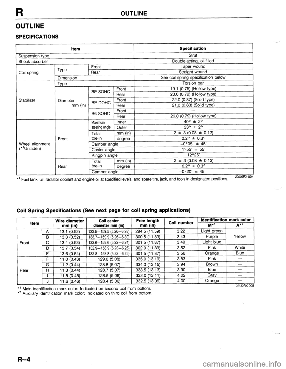
R OUTLINE
OUTLINE
SPECIFICATIONS
Suspension type Item Specification Strut
Shock absorber Double-acting, oil-filled
Coil spring
Stabilizer Type Front Taper wound
Rear Straight wound
Dimension See coil spring specification below
Type Torsion bar
BP SOHC Front 19.1 (0.75) (Hollow type)
Rear 20.0 (0.79) (Hollow type)
Diameter 22.0 (0.87) (Solid type)
mm (in) BP DOHC ;eTrt
21 .O (0.83) (Solid type)
P ,
-
66 SOHC rronr
Rear 20.0 (0.79) (Hollow type)
Maximum Inner 400 f 20
steering angle
Outer 330 f 20
Total mm (in) 2 f 3 (0.08 f 0.12)
Front toe-in
degree 0.2O f 0.3O
Wheel alignment
(*‘Unladen) Camber angle -0005’ f 45’
Caster angle 1055 * 55’
Kingpin angle 12O25’
Total mm (in) 2 f 3 (0.08 * 0.12)
Rear toe-in
degree 0.2O f 0.3O
Camber angle -0°20’ f 45’
*’ Fuel tank full; radiator coolant and engine oil at specified levels; and spare tire, jack, and tools in designated positions.
23UORX.004
Coil Spring Specifications (See next page for coil spring applications)
I Item Wire diameter Coil center Free lel.=-. .
mm iin1 rliamotor mm [in mm (in 1 coil numbs
Front
nath
1 _ . . *St Identification mark color +l
., . . . . I...,
-*.....-.“, * . . . . . ,..-, -....- I--‘, M iA*=
A 13.1 (0.52) 133.5-159.5 (5.26-6.28)
294.5 (11.59) 3.22 Light green
B 13.3 (0.52) 133.7-159.9 (5.26-6.30) 300.5 (11.83)
3.43 Purple Yellow
C 13.4 (0.53)
132.6-158.6 (5.22-6.24) 301.5 (11.87) 3.49
Light blue
D 13.7 (0.54)
132.9-158.9 (5.23-6.26) 302.0 (11.89) 3.52
Pink White
I F I 12f3 Kl5Al I 1.17 A-l!% 8 f!i PR-Fi 751
I RrIl .5 II 1 6x71 I 3.56 Orange
Blue
3 83 Pink -
Brown - .“._ \“.- .,
. “W.., ~ - -. - \-. -- -. - -, -- .-
\’ .‘-‘I t
F 11 .o (0.43) 129.0 (5.08)
335.0 (13.19) -.--
G 11.2 (0.44) 128.8 (5.07)
334.0 (13.15) 3.94
Rnnr l-4
1 I ? 07 AA 1387 /5n7
.?m !i 113 1% 3 an Blue - I I I I .” \v.-7, I&V., \V.“., ---.., \.-. .-, I 11.5 (0.45) 128.5 (5.06)
333.0 (13.11) i:oi Gray
-
J 11.6 (0.46) 128.4 (5.06)
332.5 (13.09) 4.00 Orange
-
l ’ Main identification mark color: Indicated on second coil from bottom.
*’ Auxiliary identification mark color: Indicated on third coil from bottom. 23UORX-005
R-4
Page 713 of 1164

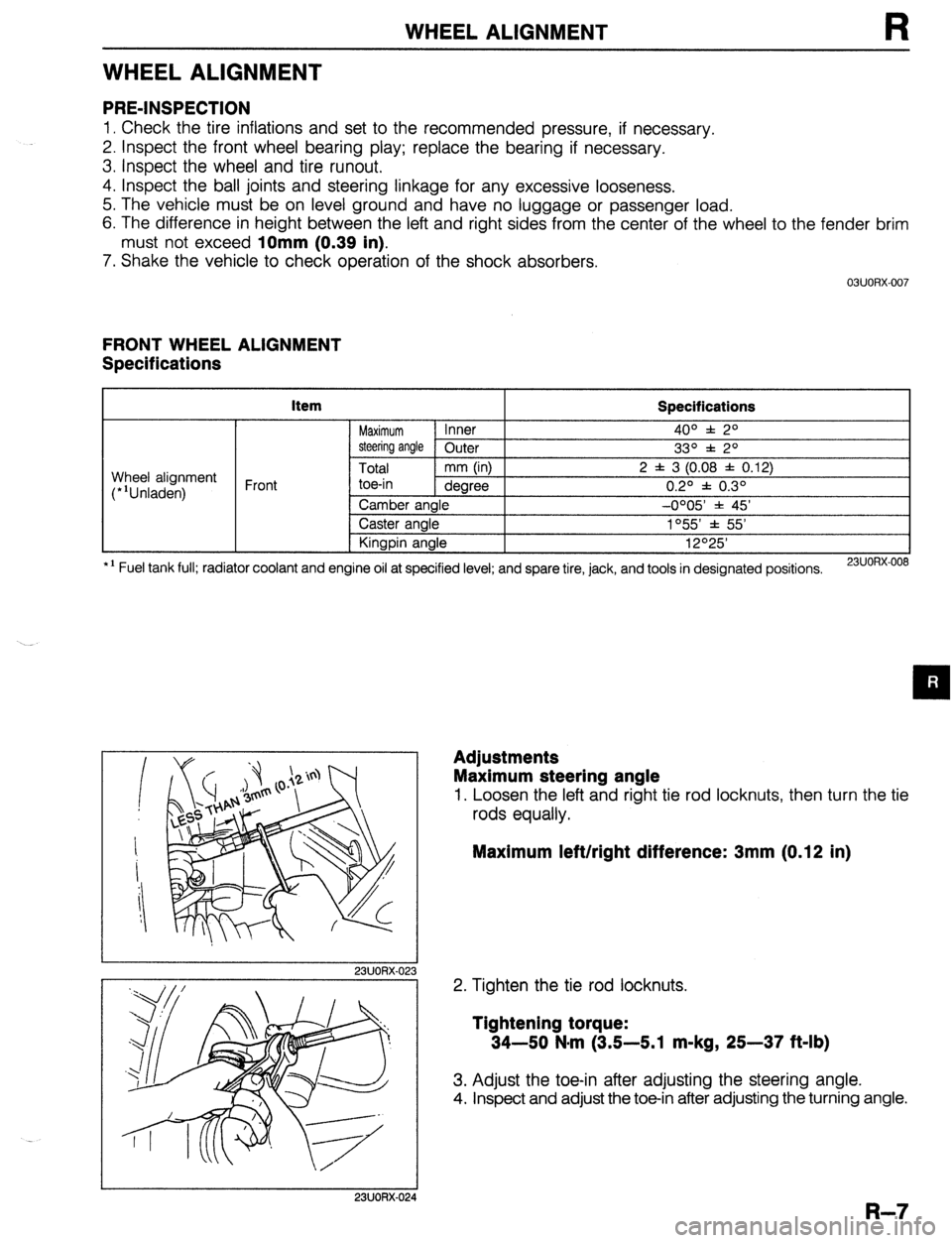
WHEEL ALIGNMENT
WHEEL ALIGNMENT
PRE-INSPECTION
1. Check the tire inflations and set to the recommended pressure, if necessary.
2. Inspect the front wheel bearing play; replace the bearing if necessary.
3. inspect the wheel and tire runout.
4. Inspect the ball joints and steering linkage for any excessive looseness.
5. The vehicle must be on level ground and have no luggage or passenger load.
6. The difference in height between the left and right sides from the center of the wheel to the fender brim
must not exceed
10mm (0.39 in).
7. Shake the vehicle to check operation of the shock absorbers.
03UORX.007
FRONT WHEEL ALIGNMENT
Specifications
item
Specifications
Maximum Inner 4o” f: 2O
steering angle Outer
33O f 2O
Total mm (in) 2 f 3 (0.08 f 0.12)
toe-in dearee 0.20 f 0.30 Wheel alignment
(*‘Unladen) Front
*I Fuel tank full; radiator coolant and Camber angle -0005 * 45’
Caster angle 1°55’ f 55’
Kingpin angle 12O25’
engine oil at specified level; and spare tire, jack, and tools in designated positions.
23UORX-008
I
I 23UORX-023
Adjustments
Maximum steering angle
1. Loosen the left and right tie rod locknuts, then turn the tie
rods equally.
Maximum left/right difference: 3mm (0.12 in)
2. Tighten the tie rod locknuts.
Tightening torque:
34-50 N-m (3.5-5.1 m-kg, 25-37 ft-lb)
3. Adjust the toe-in after adjusting the steering angle.
4. Inspect and adjust the toe-in after adjusting the turning angle.
I 23UORX-024
R-7
Page 715 of 1164

WHEEL ALIGNMENT
REAR WHEEL ALIGNMENT
Specifications
kern Specifications
Total mm (in) 2 f 3 (0.08 f 0.12)
Wheel alignment
(*‘Unladen) Rear toe-in
degree 0.2O f 0.3O
Camber angle -0020’ f 45’
*I Fuel tank full; radiator coolant and engine oil at specified level; and spare tire, jack, and tools in designated positions.
13UORX-012
Adjustment
Total toe-in
1. Loosen the lateral link locknuts.
2. Turn the lateral link adjustment link to adjust.
Note
l One turn of the link changes 11.3mm (0.44 in).
3. Tighten the lateral link locknuts to the specified torque.
Tightening torque:
55-64 N,m (5.6-6.5 m-kg, 41-47 ft-lb)
R-9
Page 977 of 1164

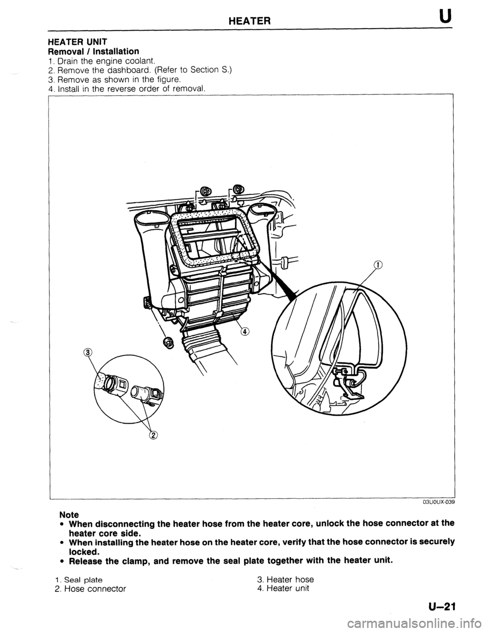
HEATER U
HEATER UNIT
Removal / Installation
1. Drain the engine coolant.
2. Remove the dashboard. (Refer to Section S.)
3. Remove as shown in the figure.
4. Install in the reverse order of removal
Note
l When disconnecting the heater hose from the heater core, unlock the hose connector at the
heater core side.
l When installing the heater hose on the heater core, verify that the hose connector is securely
locked.
l Release the clamp, and remove the seal plate together with the heater unit.
1. Seal plate 3. Heater hose
2. Hose connector
4. Heater unit
u-21
Page 1023 of 1164

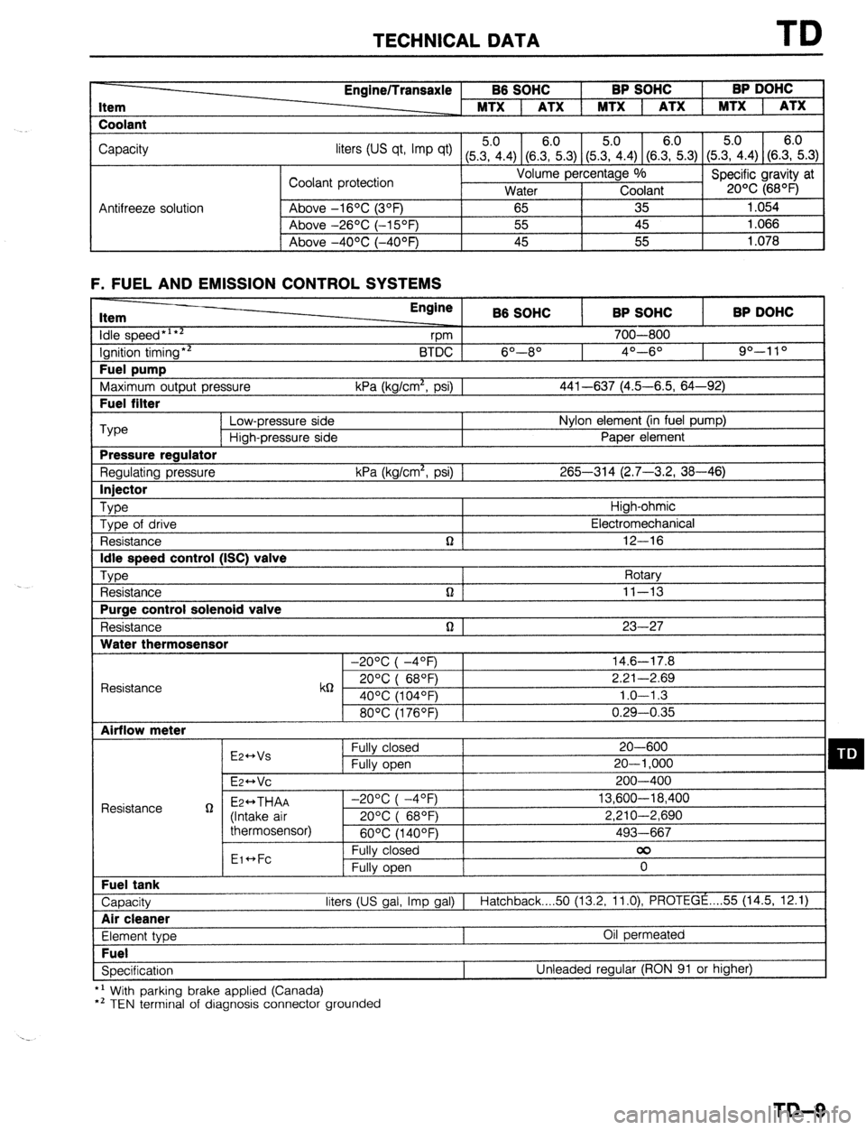
TECHNICAL DATA TD
Item
Coolant Engine/Transaxle B6 SOHC BP SOHC BP DOHC
MTX 1 ATX 1 MTX 1 ATX 1 MTX 1 ATX
Capacity
liters tus qt, Imp qt) (5Z.4) (8.E.3) (5&4) (SE.3) (5.?i.4) (S.E.3)
Coolant protection Volume percentage %
Specific gravity at
Water Coolant 20% (68OF)
Antifreeze solution Above -16OC (3OF)
65 35 1.054
Above -26OC (-15OF) 55 45 1.066
I Above -4OOC (-40°F) 45 55
1.078
F. FUEL AND EMISSION CONTROL SYSTEMS Item
idle speed*‘**
Ignition timing** Fuel pump
Maximum output pressure Fuel filter Engine
B6 SOHC BP SOHC BP DOHC
vm 700-800
BTDC 6O--8O 4O---6O 90-l 10
kPa (kg/cm*, psi) 1 441-637 (4.5-6.5, 64-92) ‘Type
Low-pressure side Nylon element (in fuel pump)
High-pressure side Paper element Pressure regulator
Regulating pressure kPa (kg/cm*, psi) 1 265-314 (2.7-3.2, 38-46) Injector
Type
High-ohmic
Type of drive Electromechanical
Resistance n 12-16 Idle speed control (ISC) valve
Type
Rotary
Resistance n ] 11-13 Purge control solenoid valve
Resistance n 1 23-27 Water thermosensor
-20°C( -4OF) 14.6-17.8
Resistance k6 20°C( 68QF) 2.21-2.69
40% (104OF) 1.0-l .3
80°C(1760F) 0.29-0.35 Airflow meter
E2++Vs Fully closed 20-600 q D Fully open 20-l ,000
E~HVC 200-400
Resistance g Ez++THAA -2O%(-4OF) 13,600-18,400
(Intake air 20%( 68OF) 2,210-2,690
thermosensor)
60°C(1400F) 493-667
Eic*Fc Fully closed 00
Fully open 0 Fuel tank
Capacity liters (US gal, Imp gal) I
Hatchback 50 (13.2, 11.0) PROTEGE . . . . 55 (14.5, 12.1) Air cleaner
Element type Oil permeated Fuel
Specification Unleaded regular (RON 91 or higher)
*’ With parking brake applied (Canada)
*’ TEN terminal of diagnosis connector grounded
TD-9
Page 1033 of 1164

TECHNICAL DATA
Q. WHEELS AND TIRES
Item Specifications
Wheel
Size
Off set Standard: 13x5-J, 14x5 l/2-JJ
Temporary
mm (in) 1 _ spare: 14x4-T
45 (1.77)
I Diameter of oitch circle
mm (in) I 100 (3.94)
r I Pl
-
Inflation pressure kPa (kg/cm*, psi) Front 1 8
I 9
Runout limit
Unbalance limit mm (in) ;lii.raltLa’
a (02) ’
13 inch wheel: 11 (0.
R. SUSPENSION Item Specifications
Suspension type Strut
)e Double-acting, oil-filled
I Shock absorber tyf
Coil spring
Type
Dimension
Type Front Taper wound
Rear Straight wound
See next page
Torsion bar
I
I C.rrn,
19.1 (0.75)
20.0 (0.79)
22.0 (0.87)
21 .O f0.83)
Wheel alignment
(“‘Unladened) BP SOHC ;;a;
Diameter
mm (in) BP DOHC - ;la;t
Front -
B6 SOHC
Rear 20.0 (0.79)
Maximum Inner 4o” f 2O
steering angle Outer
Total mm (in) 2 f 3 (0.08 j
Front toe-in
dearee
.-.._
Rear
.--. I --- ~~
Camber angle
Caster angle
Kingpin angle
I Total
I mm OnI I I toe-in
1 dearee I , --U’-- 1
Camber angle
I 33O * 2O
: 0.12)
0.2O f 0.3O
-0OO5’ * 45’
1055’ * 55’
12O25’
2 f 3 (0.08 f 0.12)
0.2O f 0.3O
-0°20’ f 45’
l ’ Fuel tank full; radiator coolant and engine ail at specified level; and spare tire, jack, and tools in designated posmons.
TD-19
Page 1050 of 1164

PARTS INDEX
I
CRANKSHAFT.. ....................................
I31 -64
CYLINDER BLOCK .............................. 61-60
CYLINDER HEAD..
............................... 81-54
CYLINDER HEAD GASKET .................
Bl-16
DRIVE BELT(S). ...................................... 81-5
FRONT OIL SEAL ................................ 81-23
HLA .............................................. Bl-7,20,60
OIL JET ................................................ 81-61
PISTON.. ...............................................
Bl-62
PISTON PIN..
........................................ 81-62
PISTON RING
....................................... 81-62
REAR
OIL SEAL..
................................. 81-25
TENSIONER, IDLER ............................. Bl-65
TENSIONER
SPRING ...........................
Bl-65
TIMING BELT ..................................
Bl-12,65
TIMING BELT PULLEY ........................
Bl-65
VALVE MECHANISM ........................... Bl-55
ENGINE
(BP DOHC) .................................... B2-2
CAMSHAFT ..........................................
82-58
CAMSHAFT PULLEY ...........................
B2-65
CONNECTING ROD..
........................... 82-63
CRANKSHAFT ......................................
B2-64
CYLINDER BLOCK ..............................
82-60
CYLINDER
HEAD.. ............................... B2-54
CYLINDER HEAD GASKET .................
82-16
DRIVE
BELTS.. .......................................
B2-5
FRONT
OIL SEAL ................................
82-26
H LA ..............................................
OIL JET .......................... B2-7iyL;;
......................
PISTON .................................................
B2-62
PISTON PIN ..........................................
82-62
PISTON RING..
..................................... 82-62
REAR OIL SEAL ................................... B2-28
TENSIONER, IDLER ............................. B2-65
TENSIONER SPRING ........................... B2-65
TIMING
BELT.. ................................
B2-12,65
TIMING BELT PULLEY ........................ 82-65
VALVE MECHANISM ........................... 82-55
ENGINE CONTROL UNIT (ECU) ............... F-149
ENGINE COOLANT
........................................ E-5
ENGINE OIL.. .................................................
D-7
ENGINE OIL FILTER.. .................................... D-8
’ EXHAUST SYSTEM. ...................................
F-136
EXTRACTOR CHAMBER .............................. S-53
F
FAN MOTOR (COOLING FAN). ................... E-14
FAN RELAY (COOLING FAN). ..................... E-18
FLASHER UNIT ............................................
T-17
FLOORMAT ..................................................
S-99
FLYWHEEL ..................................................
H-18
FRONT AXLE .................................................
M-4
FRONT BRAKE ............................................
P-l 8
FRONT BUMPER ......................................... S-39
FRONT DOOR ................................................
S-8
FRONT DOOR LOCK AND OPENER ..........
S-13
PI-2
FRONT FENDER PANEL ............................... S-7
FRONT LOWER ARM .................................. R-16
FRONT SHOCK ABSORBER AND SPRING R-11
FRONT SIDE WINDOW REGULATOR AND
GLASS ........................................................ S-10
FRONT STABILIZER..
................................... R-l 8
FRONT SUSPENSION .................................. R-l 0
FUEL FILLER LID AND OPENER..
.............. S-37
FUEL FILTER .............................................. F-l 24
FUEL GAUGE SENDER UNIT ..................... T-73
FUEL PUMP ............................................... F-125
FUEL TANK
................................................ F-123
FUSE AND JOINT BOX.. .............................. T-12
H
HEADLIGHT AND
FRONT COMBINATION LIGHT..
................ T-41
HEADLIGHT RELAY ..................................... T-l 8
HEADLINER ................................................. S-89
HEATER CONTROL UNIT.. ......................... U-26
HEATER UNIT
.............................................. U-21
HIGH-MOUNT STOPLIGHT
.......................... T-45
HIGH-TENSION LEAD ................................. G-l 7
HOOD ............................................................. S-5
HORN T-88
...........................................................
HORN RELAY
.......................................... T-18,88
.__. ’
I I
IGNITER .......................................................
G-23
IGNITION COIL.. .......................................... G-19
INJECTOR .................................................. F-l 31
INSTRUMENT CLUSTER
AND SPEEDOMETER CABLE
.................... T-69
INTAKE MANIFOLD ................................... F-113
INTERIOR LAMP ..................................... T-52,53
ISC VALVE.. ................................................ F-l 16
J
JOINT SHAFT (FRONT AXLE) .................... M-18
L
LATERAL LINK AND TRAILING LINK.. ....... R-26
LICENSE PLATE LIGHT.. ............................. T-47
i
M
I
---
MAIN RELAY (FUEL INJ. RELAY). ............ F-172
MANUAL STEERING ..................................... N-4
MANUAL TRANSAXLE (F5M-R). .................. Jl-2
Page 1088 of 1164

T.&condition
-t
Off
IQ”&” switch
ON
Whik cranking
lgnitlon switch ON
Test switch at “SELF-TEST”
Lamp illuminated for 3 sec. after ignition
SwiIch OFF-KIN
Lamp not illuminated after 3 sec. collect vdtaQe
ReRlar*
ve
For backup
ov
-
V%
Approx. tov
ov
4 5--5.5v With Self-
D&Q”& Check-
er and system
Vi3 st?lt?ctor Input &PJ
- -
0
0
0
0
0
0
- -
- -
0
0
c
- -
0 connectkfl to mnina
Connection to
Stoplight swtch Test condition
-L 1A
Bake pedal released
IEI
IC Main relay
(FUEL INJ relay) Brake pedal depressed
lQ”ih0” switch ON
___-- P/S Qrc?ss"re
switch
Ignition switch
(START) P/S ON at idle
P/S OFF at idle
A/C switch ON
A/C switch OFF
Cwlng fan operatng (Engine coolant tem-
perature over 97°C (207°F) or dlagnosls
connector terminal TFA grounded) (IG ON)
Fan not ooeralmg (Idle) 1D .self-mag”osls
Checker
(Monitor lamp) A!C switch
coohng fan swtctl
Test switch at “02 MONITOR” at idle
Monitor lamp ilfummated
Test switch at “02 MONITOR” at idle
Monitor lamp not illuminated
Lamp illuminated for 3 sec. after ignition
switch OFF&N
Lamp not illuminated after 3 ser.
Lamp illuminated
Lamp not #lluminated VB
Below 2.w With System
Selector test
VB swtch at
“SELF-TEST”
Eelow 2.5v
VS Blower Control
swttch Blower control switch OFF or 1 st posihon
Blower control swtch 2nd or htgher
position 1E
Malfunction indicator
lamp
NJ
Rear window defroster swtch OFF Rear wmdow
defroster switch
Headkght switch Rear window defroster Switch ON
-2-A - I
tieadlghts ON
Headlights OFF
Neutral positton or clutch pedal
depressed
OlhWS l Wiih Self-
DkQnosls
Checker and
Svstem Selector Self- Diaanosis Buzzer sounded for 3 sec. after ignition
switch OFF-ON
Buzzer not sounded after 3 set 6&w 2.5v
V8 Checke;
(Cede Number) I
ov Ignition swtch
ON NeulraliClutch
switches
. ‘.&h System
Selector test
switch at Buzzer sou”ded
1 Below 2.5V 1
VB
ov -
ov -
ov -
ov -
APprox. ov
or 4 5-5 5v
-
Approx. 2V
-
-
AQWOX. Ov
or 4 5-5 5v
-
APQ~OX 1.5V Buzzer not sounded
I VE
I
Ground (Injector)
Ground
(OUtQUt)
Ground (CPU)
Grou”d (Input)
constant
lgnlti swtch ON
klk “SELF-TEST”
ov
-
Ap~rox O.2V
- - Constant
Co”stant lgnller
1H
Constant
Igntho” swdch ON -
- D&ribulor
(Ne-sIgnal) II
1J
1K
1L
1M
1N -
fgnition switch ON
AX switch ON al idle
NC switch OFF at Idle
System Selector lest switch at
“0-z MONITOR” I -
- VB
5&w 2.w -
Vi3
VB Ignition switch
ON
System Selector test swatch at
“SELF-TEST”
ParkIng brake pulled wth lgndlon swtch ON
(DRL OFF) ov
VB
l DRL: oaytime Running tigms
Idle (DFtL ON) Below 2.5v A/C relay
Idle
-
Ignition swtch ON
-
Distributor
(G-stgnal) [DOHC]
3ignosis
x”“ec1or
,TEN terminal) Idle
3RL relay (canada)
-
Accelerator pedal released
Accelerafor pedal depressed
-
ov
VB
-
Ignition switch
ON rhr0ttte sensor
‘Idle switch)
Page 1089 of 1164

VE Batmy voltage
1 Ve: Battery vm
i
Remark
Termfnal Input Output Connection lo
Test conditkm
colmct voltage Remark
2W
0 Iscvalve lgmtian swdch ON
Approx. iv
-
Idle Appror. 9v
2x
0 Solenoid valve
lgnitlon switch ON
VS
(Purge control) -
IUk
VB
2Y - - -
-
-
@i switch
)N le
I!
C
4
-C
,
,
e
”
3
-C
.
f
-
-
-
)nition switch
)N I I I
I I
I -
22 - - -
- -
-
-
-
luilt in airflow
1eter
lnition swttch
)N
-
VICS: Vata&
Inertia charging
SYStem loaHCl
-
Engine Signal
Monitor: Green
and red lamps
flash
mnin
2H
- I Main relay (w=w I Ignition switch ON
VB
_/I/ - I -
I - 21
25
-7 I - I -
I - , I t 0 Air-flow meter constant
4.5-5.5v 2K
I I I
I
0 I 1 Thr0tlle sensor Accekrator pedal r&eased
4.5-5-W
I I (Power switch)
Accelerator pedal fuUy depessed ov
2M
l-l - I -
-
I -
0 oxygen sensw Ignitia switch ON
ov
Idle (Cold engine) ov
Idle (After “ram-up)
O-l .ov
Increasing engine speed (After warm-up) 0.5v-1 .ov
oeceleratlon
0-0.4v
0 Airflow meter Ignition switch ON
Ap~rox 3 8L
ldk Approx. 3.3 2N
20
2P
0 Intake air ther- Ambient air temperature 20°C (68” F)
mosensor
W W Ap&xox 2 5V
0 water thermosensor Enaine coolant temperature 20°C (68°F)
ADDTOX 2.5\( 20
2R
2s
,.
After “am-up B&w 0 5v
I I I I
- - - - -
0 Sdenoid valve Engine speed below 5.000 rpm Below 1 5v
ww
Engine speed above 5.000 rpm VB
2T I 0 lsolertoid valve
I60 jDOHCl/l20 ISOHCI seconds after en- 1
/ I--
temperature abo& 56°C (136 o F)
(OOHC]/SO”C (122°F) (SOHC]
0 Injector (Nos. 1.3) Other condition at idle VB
Ignition switch ON
Vt7
Idle
VB‘ 2u
2v Engine speed above 2.000 rpm on
decderation (After warm-up) Ve
0 Injector (NOS. 2. 4) Ignition swatch at id& VB
idle
VS.
Engine speed above 2,000 rpm on
deceteratiin (After warm-up) VS
Page 1096 of 1164

Terminal vdt
wminal lrput
1A -
1B 0
-
1C 0
1D e (ATX) ve: aattefy voltage
1
Connected to
I Test wndition ~cwrect rc4t.gej F&W*
-
0
-
-
3attery
Uain r&y
:FUEL INJ relay) Constant
tgnition swdch V% For backt@
OFF ov
ON V6
Ignition swtch
(START)
Self-Diagnosis
Checker
[monitor lamp)
3 - White crankii npprox 1ov
fgnition switch ON ov
Test swtch at “SELF-TEST’ With Self-
Lamp illuminated for 3 sec. after igmtmn 4.5-5.w Diagnosis Check-
switch OFF-+ON er and System
Selector
Lamp net illuminated after 3 Sec. VS
Test swtch at “02 MONITOR” at idle
i Monitor lamp illuminated 4.5-55v
Test switch at “02 MONtTOR” at idfe
Monitor lamp not illuminated
Malfunction indicator
lamp illuminated for 3 sec. after ignition
Below 2 5v With System
lalllp switch OFF+ON selector test
WLI switch at
Lamp not luminated after 3 sec. VE
“SELF-TEST”
lamp ifluminated BelOW 2.w
Lamp not illuminated VS
Self-Diagnosis Buzzer sounded for 3 sec. after ignrtion
l With Self-
Checker switch OFF-+ON Below 2.5V
Diagm!3s
(code number) Checker and
Buzzer not sounded after 3 set VB
system
Select0 Buzzer sou&?d Below 2 5v l With System
Selector test
I Buzzer not sounded
tgmter Ignition switch ON ov
Idle Appror 0 2v -
Headlight switch Headlights ON
f VB
-
Headlbhts OFF ! ov
Diagnosis
connector
, System Selector test switch at
VS Ignition witch
“02 MONITOR” ON
(TEN terminal)
Rear window
defroster switch
Ground Icalifornia) System Selector tesf switch at
“SELF-TEST”
Rear window defroster watch OFF
Rear window de!roster watch ON
ConSlant QV
ov lgmhon switch
__ ON
VO
ov
- Main relay (canadal fgmtion switch ON VB
AC relay Ignitiin switch ON VB
A/C switch ON at Idle Below 2.5% -
Vehicle speed A/C switch OFF at Gle
/ Vehicle stopped
P/S pressure
switch lgmhon switch ON
P/S ON at idle Iturnino)
I.
P/S OFF at idle I VB Terminal voltage v‘s: Battery vottage
I I
1
Terminal input Output Connected to Test condition comcl voltage Remark
10
0 A/C swatch AIC switch ON Befow25V ignition switch
ON and blower
A/C switch OFF VB I
motor ON
IP
ii Blower control Blower control swtch OFF or 1 St poSItion VB tgnibon switch
switch ON
Blower control switch 2nd or higher
ov
position
1Q
0 Stopltght switch Brake pedal released Below 1 ov
-
IT <; Brake pedal depressed VE
lnhtbitor switch N or P range ov Ignition switch
(P N range) ON
Other ranges VB
Cruise control man Set or Resume swtch ON or vehicle speed lgmhon swtch
switch 8kmih &mph) lower than preset speed &tow 1 5~ ON
(Drwng vehcfe crwse cantrol
OperatiOn)
Fk
z 1v -
3A ’ Throttle Sensor
(Idle switch) Normal conditions
Accelerator pedal released
Accelerator pedal depressed “8
Bebw 1 ov lgnihon swatch
ON
VS
I -
-
- - -
-
-
- - -
D&rib&r
-‘. / b / / (Ne-signal) lgmtion swtch ON
/ ,,,, Approx. OV
or 5v
-
Approx 2v
I ._.
/
28 1
AdlOw meter lgmhon switch ON
Approx 3 BV .,
-
Idle Approx 3 3V
2c j r:
I \’ oxygen sensor fgmtson switch ON ov
1
20 Idle (cold englIIei
Idle (after warn-up)
lncreasma enwe speed (after warm-up) ov
O-l ov -
0 w-1 .ov
_ -
,
Deceleration o-o 4v
Coolmg fan swtch Fan operahng (engine coolant temperature
over 97°C (207’F) or diagnosis connector DV
termmat TFA grounded) -
Fan not operatmg (idle)
Water thermosensor Engine codant temperature L” %, I”” I , ‘Y”8’.“” . . . ...-1.
After warm-up
I
Thrnttb SP”SOi 1 Accelerator pedal released Approx 0.5V
2G .._..._ --..--
-
Accelerator pedal fully depressed Approx. 4 OV
0 ATF thermosensor -XPC (-2o”~)--1x1~c (302°F) aprxox as5-~m lgmhon swtch
ON
ATF temp 20°C (68°F) Approx. 4.6V
13OOC (266°F) Aporox 1.54V
I I I I I I
2H / i, I / Hold switch Hold mode Below 2V Ingbhon switch
Normal mode