MAZDA PROTEGE 1992 Workshop Manual
Manufacturer: MAZDA, Model Year: 1992, Model line: PROTEGE, Model: MAZDA PROTEGE 1992Pages: 1164, PDF Size: 81.9 MB
Page 861 of 1164

INDEX T
INTERIOR LAMPS
23UOTX-OC
1. Spot lamp (in overhead console)
Removal / Inspection /
Installation ,,,,,.,,,.,..,.,................. page T-52
2. Interior and spot lamp (Without sunroof)
Removal / Inspection I
Installation .,,........,.....,.,............. page T-53
3. Interior lamp (Without sunroof)
Removal / Inspection /
Installation . . . . . . . . . . . . . . . . . . . . . . . . . . . . . . . . . page T-52
4. Interior lamp (With sunroof)
Removal I Inspection I
Installation . . . . . . . . . . . . . . . . . . . . . . . . . . . . . . . . . page T-53 5. IG key illumination
Troubleshooting .,.,..........,........... page T-50
6. Cargo compartment lamp
Removal I Inspection I
Installation . . . . . . . . . . . . . . . . . . . . . . . . . . . . . . . . . page T-54
7. Trunk compartment lamp
Removal I Inspection I
Installation ..,.,...,...........*............ page T-54
8. Door switch
Inspection . . . . . . . . . . . . . . . . . . . . . . . . . . . . . . . . . . .
page T-51
9. Courtesy lamp
Removal I Inspection I
Installation . . ,.., . . . ., ,, . . ,...... . . . . . . . . . . . page T-54
T-5
Page 862 of 1164

T INDEX
CRUISE CONTROL SYSTEM
23UOTX-004
1. Cruise control switch
Removal / Installation . . . . . . . . . . . . . . . . . . page T-20
Inspection . . . . . . . . . . . . . . . . . . . . . . . . . . . . . . . . . . . page T-21
2. Speed sensor (in the meter)
Inspection ,,,,..~..,,,..,,,.,........,.,..,.. page T-72
3. Actuator
Inspection . . . . . . . . . . . . . . . . . . . . . . . . . . . . . . . . . . . page T-87
4. Cruise control unit
Troubleshooting . . . . . . . . . . . . . . . . . . . . . . . . . . page T-83
Removal / Installation . . . . . . . . . . . . . . . . . . page T-85
Self-diagnostic inspection . . . . . . . . . . . page T-80
Inspection . . . . . . . . . . . . . . . . . . . . . . . . . . . . . . . . . . . page T-86 5. Stoplight switch
Inspection . . . . . . . . . . . . . . . . . . . . . . . . . . . pages T-47, 87
Adjustment . . . . . . . . . . . . . . . . . . . . . . . . . . page T-87
6. Clutch switch (For MTX)
Adjustment ..,,....,...,..,..,,....., page T-87
7. Cruise control main switch
Inspection . . . . . . . . . . . . . . . . . . . . . . . . . . . page T-21
T-6
Page 863 of 1164

INDEX T
AUDIO ’
1. Audio component 3. Rear speaker
Troubleshooting ........................ page T- 92 Troubleshooting ........................ page T- 92
Removal / Installation
................ page T- 98 Removal / Installation ................
page T- 99
2. Door speaker Inspection ................................. page T- 99
Troubleshooting ........................
page T- 92 4. Antenna feeder
Removal / Installation
................ page T- 98 Troubleshooting ........................ page T- 92
Inspection ................................. page T- 99 Removal.. .................................. page T- 99
Installation .................................
page T-l 00
Inspection .................................
page T-100
T-7
Page 864 of 1164

T INDEX
OTHER
1, Joint box (including CPU)
Removal / Installation . . . . . . . . . . . . . . . . . . page T-l 5
Inspection . . . . . . . . . . . . . . . . . . . . . . . . . . . . . . . . . . . page T-58
2. Circuit breaker
Note . . . . . . . . . . . . . . . . . . . . . . . . . . . . . . . . . . . . . . . . . . . .
page T-14
3. Horn
Removal I Installation . . . . . . . . . . . . . . . . . . page T-88
23UOTX-OOf
4. Main fuse
Removal I Installation . . . . . . . . . . . . . . . . . . page T-14
5. Rear window defroster (Filament)
Troubleshooting ,..........,,...,........,
page T-75
Inspection . . . . . . . . . . . . . . . . . . . . . . . . . . . . . . . . . . . page T-77
Repairing . . . . . . . . . . . . . . . . . . . . . . . . . . . . . . . . . . . .
page T-77
T-8
Page 865 of 1164

OUTLINE
OUTLINE
HOW TO USE THIS SECTION
Information regarding removal and installation of electrical equipment is given in SECTION S.
Understanding will be easier if this section is used in conjunction with the WIRING DIAGRAMS.
9MUOTX-008
1.4W or 3.4W
23UOTX.07 1
61G15X-002
69G15X-00 3
63U 15X-005
ELECTRICAL TROUBLESHOOTING TOOLS
Test Light
The test light, as shown in the figure, uses a battery voltage
bulb. The two leads should be connected to probes. The test
light is used for simple voltage checks and to check for open
circuits.
Caution
l When checking the control unit, never use a bulb
over 3.4W.
Jumper Wire
The jumper wire is used for testing by short-circuiting switch
terminals and for verifying the condition of ground connections.
Caution
l Do not connect the jumper wire between a power
source line and body ground because this may
cause burning or other damage to harnesses or
electronic components.
The DC voltmeter is used for measuring circuit voltage. A volt- q Voltmeter
meter with a range of 15V or more is used by connecting the
positive (+) probe (red lead) to the point where voltage is to
be measured, and the negative (-) probe (black lead) to the
body ground.
Ohmmeter
The ohmmeter is used to measure the resistance between two
points in a circuit, and is also used to check for continuity and
diagnosis of short circuits.
Caution
l Do not attempt to connect the ohmmeter to any cir-
cuit to which voltage is applied because this may
burn or otherwise damage the ohmmeter.
T-9
Page 866 of 1164

T
ELECTRICAL SYMBOLS
Switches and Relays OUTLINE
There is an NC (normally closed) and NO (normally open) indication for switches and relays which shows
when no change of operation conditions has occurred.
Relay Switch
NO type relay NC type relay NO switch NC switch
Not in operation
(No power supply) +E+ #Fig -o-- -da--
ax ax
STOP
FLOW STOP FLOW
In operation
(Power supply) * !jiij! kiig 6 dLe
cw r”X
FLOW STOP FLOW STOP
Other Electrical Symbols
BATTERY
THERMISTER DIODE CONDENSER
Q
M
MOTOR I
T-10
l-
BODY GROUND
COIL, SOLENOID i
0 8 HOLDER BOX
FUSE
RESISTOR
1
T
FUSIBLE LINK
1 i 1
VARIABLE RESISTOR
LIGHT
HEATER
69G15X-O(
Page 867 of 1164

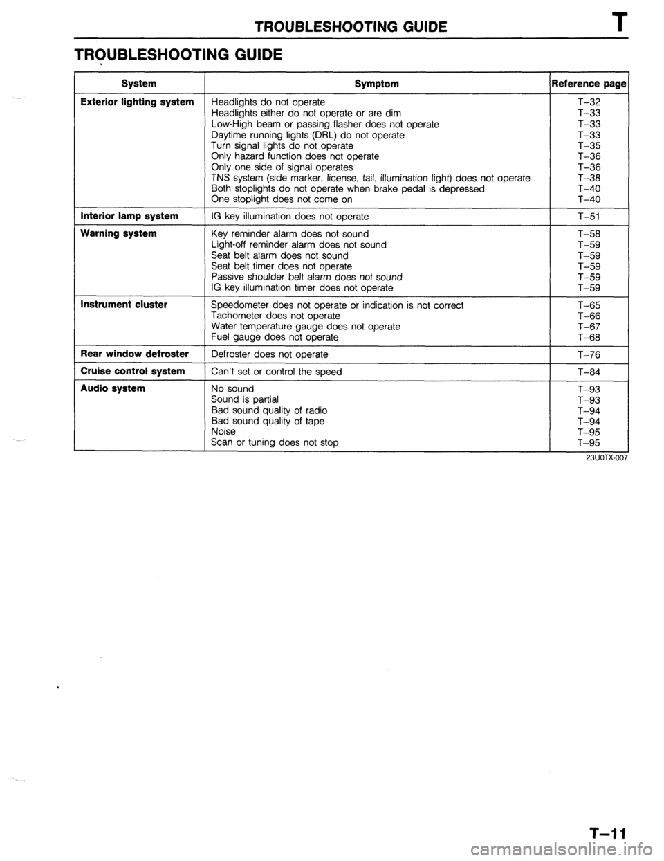
TROUBLESHOOTING GUIDE T
TROUBLESHOOTING GUIDE
System
Exterior lighting system
Interior lamp system
Warning system
Instrument cluster
Rear window defroster
Cruise control system
Audio system Symptom Reference page
Headlights do not operate T-32
Headlights either do not operate or are dim T-33
Low-High beam or passing flasher does not operate T-33
Daytime running lights (DRL) do not operate T-33
Turn signal lights do not operate T-35
Only hazard function does not operate T-36
Only one side of signal operates
T-36
TNS system (side marker, license, tail, illumination light) does not operate T-38
Both stoplights do not operate when brake pedal is depressed T-40
One stoplight does not come on T-40
IG key illumination does not operate
T-51
Key reminder alarm does not sound
Light-off reminder alarm does not sound
Seat belt alarm does not sound
Seat belt timer does not operate
Passive shoulder belt alarm does not sound
IG key illumination timer does not operate T-58
T-59
T-59
T-59
T-59
T-59
Speedometer does not operate or indication is not correct
Tachometer does not operate
Water temperature gauge does not operate
Fuel gauge does not operate
Defroster does not operate
Can’t set or control the speed T-65
T-66
T-67
T-68
T-76
T-84
No sound
Sound is partial
Bad sound quality of radio
Bad sound quality of tape
Noise
Scan or tuning does not stop T-93
T-93
T-94
T-94
T-95
T-95
T-l 1
Page 868 of 1164

T FUSE AND JOINT BOX
FUSE AND JOINT BOX
STRUCTURAL VIEW
13UO-wOl(
1. Main fuse
3. Joint box
Removal I Installation
.................. page T-14 Removal I Installation
.................. page T-l 5
2. Fuse
Inspection ...................................
page T-58
Removal / Installation
.................. page T-l 4
T-12
Page 869 of 1164

FUSE AND JOINT BOX
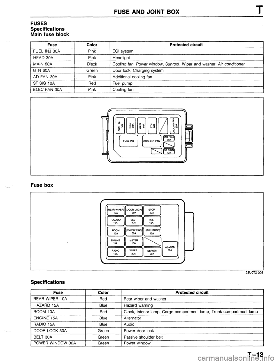
FUSES
Specifications
Main fuse block
Fuse Color
FUEL INJ 30A Pink
HEAD 30A Pink
MAIN 80A Black
BTN 60A Green
AD FAN 30A Pink
ST SIG 10A Red
ELEC FAN 30A Pink Protected circuit
EGI system
Headlight
Cooling fan, Power window, Sunroof, Wiper and washer, Air conditioner
Door lock, Charging system
Additional cooling fan
Fuel pump
Cooling fan
Fuse box
23UOTX-001
Specifications
Fuse
REAR WIPER 10A
HAZARD 15A
ROOM IOA
ENGINE 15A
RADIO 15A
DOOR LOCK 30A
BELT 30A
POWER WINDOW 30A Color
Red
Blue
Red
Blue
Blue
Green
Green
Green Protected circuit
Rear wiper and washer
Hazard warning
Clock, interior lamp, Cargo compartment lamp, Trunk compartment lamp
Alternator
Audio
Power door lock
Passive shoulder belt
Power window
1
T-13
Page 870 of 1164

T FUSE AND JOINT BOX
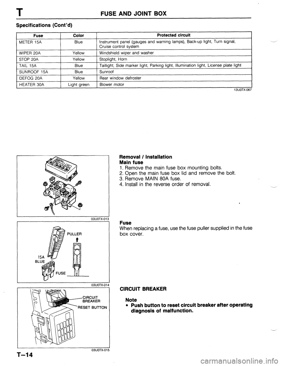
Specifications (Cont’d)
Fuse Color
METER 15A Blue
WIPER 20A Yellow
STOP 20A Yellow
TAIL 15A
Blue
SUNROOF 15A Blue
DEFOG 20A Yellow
HEATER 30A Light green Protected circuit Instrument panel (gauges and warning lamps), Back-up light, Turn signal,
Cruise control system
Windshield wiper and washer
Stoplight, Horn
Taillight, Side marker light, Parking light, Illumination light, License plate light
Sunroof
Rear window defroster
Blower motor
13UOTX-067
L
r 03UOTX-01
1 BL
PULLER
t
L 03UOTX-01
CIRCUIT
BREAKER
RESET BUTTON
03UOTX.01
Removal / Installation
Main fuse
1. Remove the main fuse box mounting bolts.
2. Open the main fuse box lid and remove the bolt.
3. Remove MAIN 80A fuse.
4. Install in the reverse order of removal.
Fuse
When replacing a fuse, use the fuse puller supplied in the fuse
box cover.
CIRCUIT BREAKER
Note
l Push button to reset circuit breaker after operating
dlagnosls of malfunction.
5
T-14