charging MAZDA PROTEGE 1992 Workshop Manual
[x] Cancel search | Manufacturer: MAZDA, Model Year: 1992, Model line: PROTEGE, Model: MAZDA PROTEGE 1992Pages: 1164, PDF Size: 81.9 MB
Page 12 of 1164
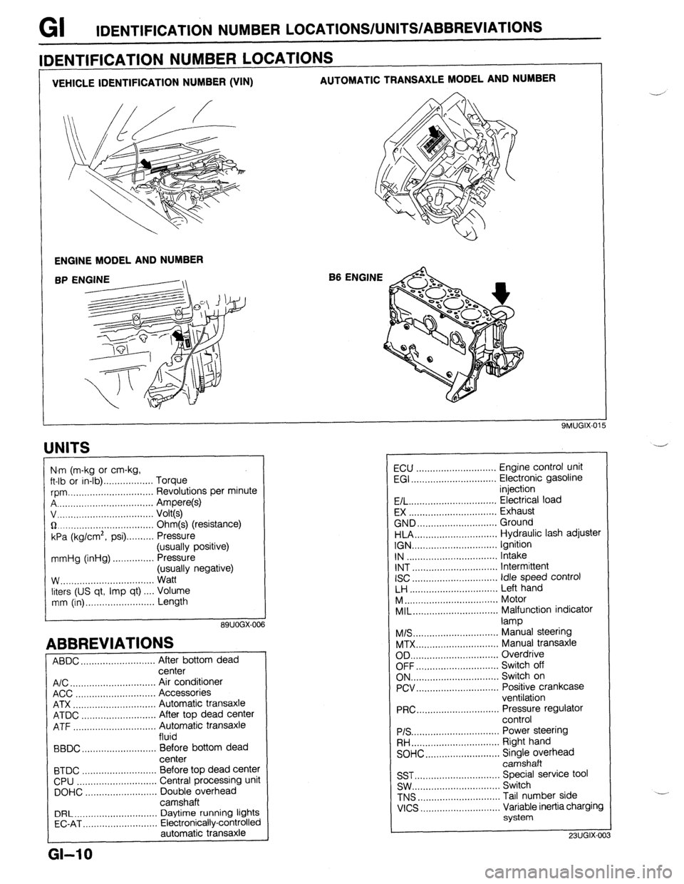
GI IDENTIFICATION NUMBER LOCATIONS/UNITS/ABBREVlATlONS
VEHICLE IDENTIFICATION NUMBER (VIN) AUTOMATIC TRANSAXLE MODEL AND NUMBER
ENGINE MODEL AND NUMBER
B6 ENGINE
IDENTIFICATION NUMBER LOCATIONS
UNITS
I
N.m (m-kg or cm-kg,
ft-lb or in-lb) . . . . . . . . . . . . . . . . . . Torque
rpm ._..,,,.............,.......... Revolutions per minute
A . . . . . . . . . . . . . . . . . Ampere(s)
v, . . . . . . . . . . . . . .
Volt(s)
$2 _....._..,......................... Ohm(s) (resistance)
kPa (kg/cm2,
psi) . . . . . . . . . . Pressure
(usually positive)
mmHg (inHg) . . . . . . . . . . . . . . . Pressure
(usually negative)
W.. . . . . . . . . . . .
Watt
liters (US qt, Imp qt) ,... Volume
mm (in) ..,......,...,........... Length
89UOGX-00
ABBREVIATIONS
ABDC . . . . . . . . . . . . . . . . . . . . .
After bottom dead
center
A/C . . . . . . . . . . . . . . . . . . . . . . . . . . . . . . .
Air conditioner
ACC ..,.,...... 3 . . . . . . . . . . . . . . . . . Accessories
ATX . . . . . . . . . . . . . . . . . . . . . . . . . . . . . . Automatic transaxle
ATDC ..,,...,...,............... After top dead center
ATF . . . . . . . . . . . . . . . . . Automatic transaxle
fluid
BBDC ,,..,.......,...,......,... Before bottom dead
center
BTDC .,......,...............,.. Before top dead center
CPU ..,,.......,...,..........,.. Central processing unit
DOHC ..,...,..,............,,.. Double overhead
camshaft
DRL ____.......................... Daytime running lights
EC-AT .,_.......,............,,.. Electronically-controlled
automatic transaxle
L
GI-10
ECU ............................. Engine control unit
EGI ............................... Electronic gasoline
injection
E/L.. .............................. Electrical load
EX ................................ Exhaust
GND.. ........................... Ground
HLA.. ............................ Hydraulic lash adjuster
IGN ............................... Ignition
IN ................................. Intake
INT ............................... Intermittent
ISC
............................... idle speed control
LH ................................ Left hand
M..
................................ Motor
MIL..
............................. Malfunction indicator
lamp
M/S..
............................. Manual steering
MTX.. ............................ Manual transaxle
OD ................................ Overdrive
OFF.. ............................ Switch off
ON.. .............................. Switch on
PCV.. ............................ Positive crankcase
ventilation
PRC..
............................ Pressure regulator
control
PIS ................................ Power steering
RH..
.............................. Right hand
SOHC.. .........................
z;;kiprhead
SST ............................... Special service tool
SW.. .............................. Switch
TNS
.............................. Tail number side
VICS
............................. Variable inertia charging
system
23UGIX-00
Page 267 of 1164
F
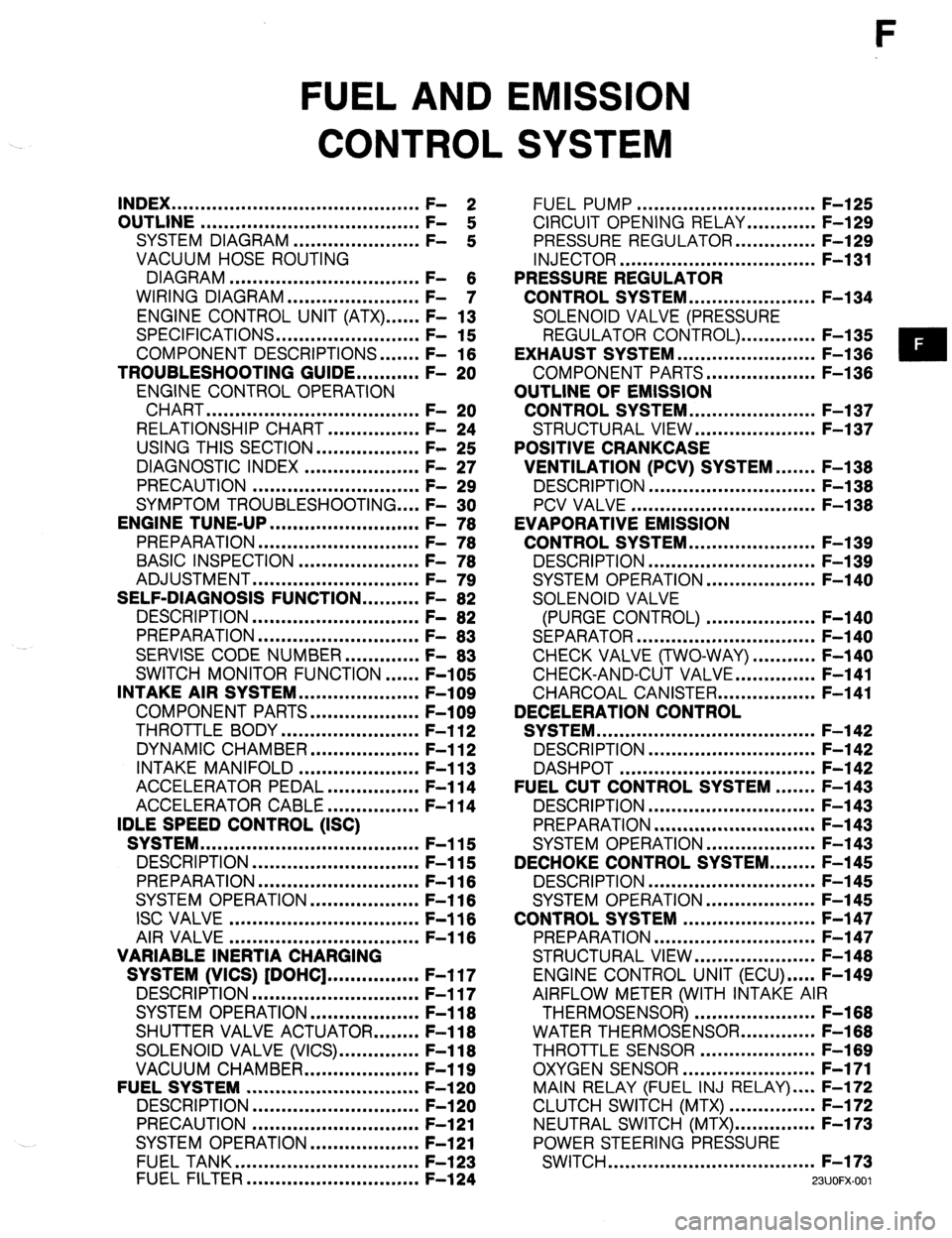
FUEL AND EMISSION
CONTROL SYSTEM
INDEX ...........................................
OUTLINE ...................................... ;: 2
SYSTEM DIAGRAM ...................... F-
:
VACUUM HOSE ROUTING
DIAGRAM .................................
WIRING DIAGRAM ....................... F- 6
- 7
ENGINE CONTROL UNIT (ATX) ...... F- 13
SPECIFICATIONS.. ....................... F- 15
COMPONENT DESCRIPTIONS.
...... F- 16
TROUBLESHOOTING GUIDE.. ......... F- 20
ENGINE CONTROL OPERATION
CHART
..................................... F- 20
RELATIONSHIP CHART.. .............. F- 24
USING THIS SECTION .................. F- 25
DIAGNOSTIC INDEX .................... F- 27
PRECAUTION ............................. F- 29
SYMPTOM TROUBLESHOOTING .... F- 30
ENGINE TUNE-UP
.......................... F- 76
PREPARATION ............................
F- 76
BASIC INSPECTION ..................... F- 78
ADJUSTMENT .............................
F- 79
SELF-DIAGNOSIS FUNCTION .......... F- 82
DESCRIPTION .............................
F- 82
PREPARATION
............................
F- 83
SERVISE CODE NUMBER.. ........... F- 83
SWITCH MONITOR FUNCTION ...... F-105
INTAKE AIR SYSTEM.. ................... F-109
COMPONENT PARTS.. ................. F-109
THROTTLE BODY ........................ F-l 12
DYNAMIC CHAMBER ................... F-l 12
INTAKE MANIFOLD ..................... F-l 13
ACCELERATOR PEDAL ................ F-l 14
ACCELERATOR CABLE ................ F-l 14
IDLE SPEED CONTROL (ISC)
SYSTEM ......................................
F-115
DESCRIPTION ............................. F-115
PREPARATION
............................ F-116
SYSTEM OPERATION.. ................. F-l 16
ISC VALVE ................................. F-116
AIR VALVE
................................. F-116
VARIABLE INERTIA CHARGING
SYSTEM (VICS) [DOHC] ................ F-l 17
DESCRIPTION ............................. F-117
SYSTEM OPERATION ................... F-l 18
SHUTTER VALVE ACTUATOR.. ...... F-l 18
SOLENOID VALVE (VICS). ............. F-118
VACUUM CHAMBER.. .................. F-119
FUELSYSTEM .............................. F-l 20
DESCRIPTION
............................. F-l 20
PRECAUTION ............................. F-121
SYSTEM OPERATION.. ................. F-121
FUEL TANK ................................
F-l 23
FUEL FILTER .............................. F-l 24 FUEL PUMP ............................... F-l 25
CIRCUIT OPENING RELAY.. .......... F-129
PRESSURE REGULATOR.. ............ F-129
INJECTOR .................................. F-l 31
PRESSURE REGULATOR
CONTROL SYSTEM.. .................... F-l 34
SOLENOID VALVE (PRESSURE
REGULATOR CONTROL). ............ F-l 35
EXHAUST SYSTEM ........................ F-l 36
COMPONENT PARTS.. ................. F-136
OUTLINE OF EMISSION
CONTROL SYSTEM.. .................... F-l 37
STRUCTURAL VIEW.. ................... F-l 37
POSITIVE CRANKCASE
VENTILATION (PCV) SYSTEM.. ..... F-138
DESCRIPTION .............................
F-l 38
PCV VALVE ................................ F-l 38
EVAPORATIVE EMISSION
CONTROL SYSTEM.. .................... F-l 39
DESCRIPTION ............................. F-l 39
SYSTEM OPERATION.. ................. F-140
SOLENOID VALVE
(PURGE CONTROL) ................... F-140
SEPARATOR ............................... F-l 40
CHECK VALVE (TWO-WAY) ........... F-140
CHECK-AND-CUT VALVE.. ............ F-141
CHARCOAL CANISTER.. ............... F-141
DECELERATION CONTROL
SYSTEM ...................................... F-l 42
DESCRIPTION ............................. F-l 42
DASHPOT .................................. F-142
FUEL CUT CONTROL SYSTEM ....... F-143
DESCRIPTION ............................. F-l 43
PREPARATION ............................ F-l 43
SYSTEM OPERATION.. ................. F-143
DECHOKE CONTROL SYSTEM.. ...... F-145
DESCRIPTION ............................. F-l 45
SYSTEM OPERATION ................... F-l 45
CONTROL SYSTEM ....................... F-l 47
PREPARATION ............................ F-147
STRUCTURAL VIEW.. ................... F-l 48
ENGINE CONTROL UNIT (ECU) ..... F-149
AIRFLOW METER (WITH INTAKE AIR
THERMOSENSOR) ..................... F-168
WATER THERMOSENSOR.. ........... F-168
THROTTLE SENSOR .................... F-l 69
OXYGEN SENSOR.. ..................... F-171
MAIN RELAY (FUEL INJ RELAY) .... F-172
CLUTCH SWITCH (MTX) ............... F-172
NEUTRAL SWITCH (MTX). ............. F-173
POWER STEERING PRESSURE
SWITCH .................................... F-173
WJOFX-001
Page 283 of 1164
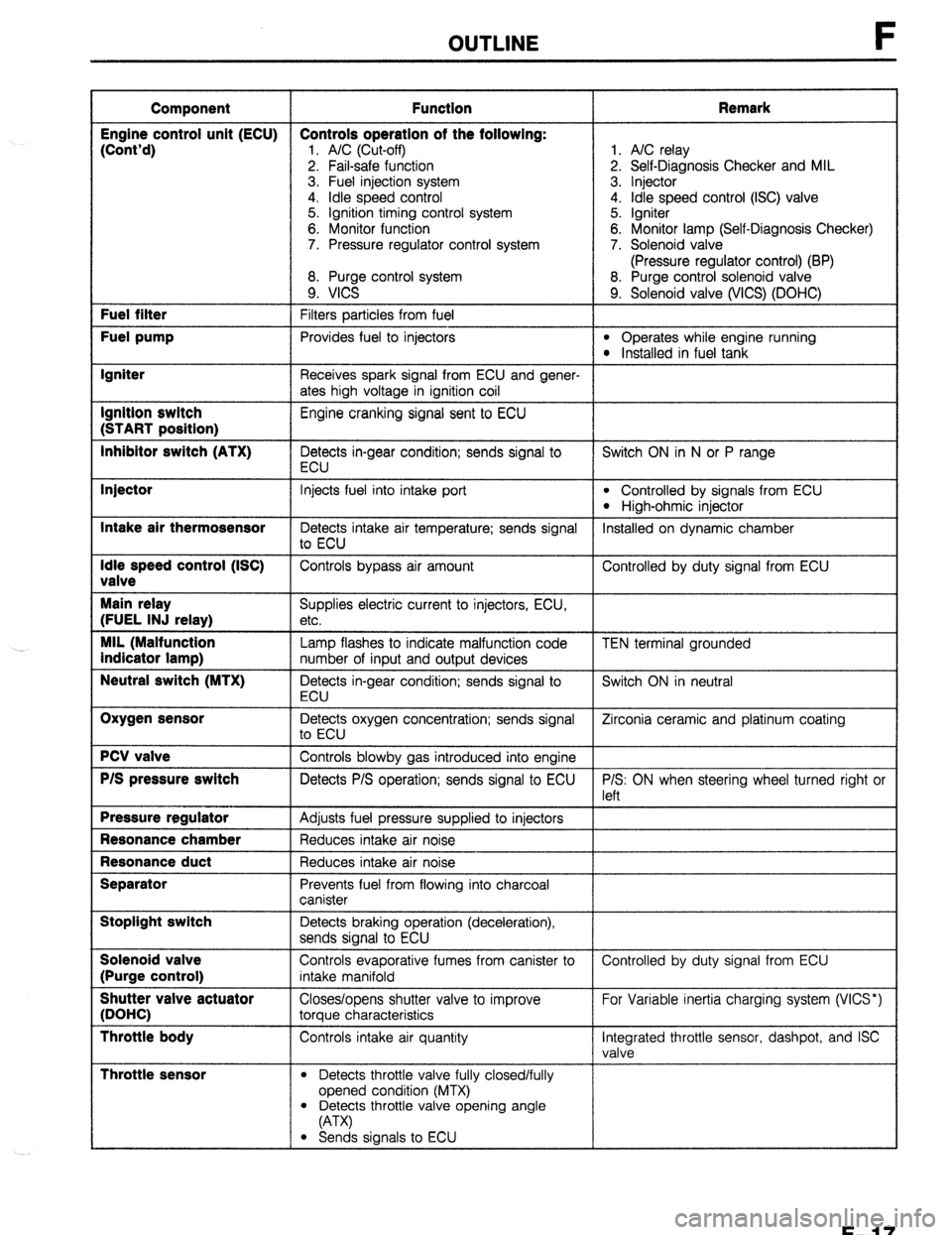
OUTLINE
Component Function Remark
Engine control unit (ECU) Controls operation of the following:
(Cont’d)
1. A/C (Cut-off) 1. A/C relay
2. Fail-safe function 2. Self-Diagnosis Checker and MIL
3. Fuel injection system 3. Injector
4. idle speed control 4. Idle speed control (ISC) valve
5. Ignition timing control system 5. Igniter
6. Monitor function 6. Monitor lamp (Self-Diagnosis Checker)
7. Pressure regulator control system 7. Solenoid valve
(Pressure regulator control) (BP)
8. Purge control system 8. Purge control solenoid valve
9. VICS 9. Solenoid valve (WCS) (DOHC) Fuel filter
Filters particles from fuel Fuel pump
Provides fuel to injectors l Operates while engine running l Installed in fuel tank Igniter
Receives spark signal from ECU and gener-
ates high voltage in ignition coil Ignition switch
Engine cranking signal sent to ECU (START position)
Inhibitor switch (ATX)
Detects in-gear condition; sends signal to Switch ON in N or P range
ECU Injector
Intake air thermosensor
Idle speed control (ISC)
valve
Main relay
(FUEL INJ relay)
MIL (Malfunction
indicator lamp)
Neutral switch (MTX)
Oxygen sensor
PCV valve
P/S pressure switch
Pressure regulator
Resonance chamber
Resonance duct
Separator
Stoplight switch
Solenoid valve
(Purge control)
Shutter valve actuator
(DOHC)
Throttle body
Throttle sensor
Injects fuel into intake port l Controlled by signals from ECU
l High-ohmic injector
Detects intake air temperature; sends signal Installed on dynamic chamber
to ECU
Controls bypass air amount Controlled by duty signal from ECU
Supplies electric current to injectors, ECU,
etc.
Lamp flashes to indicate malfunction code
number of input and output devices
Detects in-gear condition; sends signal to
ECU
Detects oxygen concentration; sends signal
to ECU
Controls blowby gas introduced into engine
Detects P/S operation; sends signal to ECU
Adjusts fuel pressure supplied to injectors
Reduces intake air noise
Reduces intake air noise
Prevents fuel from flowing into charcoal
canister
Detects braking operation (deceleration),
sends signal to ECU
Controls evaporative fumes from canister to
intake manifold
Closes/opens shutter valve to improve
torque characteristics
Controls intake air quantity
l Detects throttle valve fully closed/fully
opened condition (MTX) TEN terminal grounded
Switch ON in neutral
Zirconia ceramic and platinum coating
P/S: ON when steering wheel turned right or
left
Controlled by duty signal from ECU
For Variable inertia charging system (VICS*)
Integrated throttle sensor, dashpot, and ISC
valve
l Detects throttle valve opening angle
(A-W
l Sends signals to ECU
F-l 7
Page 284 of 1164

F OUTLINE
I Component
I Function
I Remark
I
Three-way
solenoid
valve vIcs*
Pressure
regulator
control
Controls vacuum to shutter valve actuator
Controls vacuum to pressure regulator Cuts vacuum when engine speed above
5.000 ram
Cuts vacuum just after starting when engine
hot starting Vacuum chamber
(DOHC)
Water thermosensor
Stores vacuum for use during wide open For WCS*
throttle
Detects coolant temperature; sends signal to
ECU
l WCS: Variable Inertia Charging System 23UOFX-013
F-l 8
Page 330 of 1164

TROUBLESHOOTING GUIDE
ISTEP 1 INSPECTION
15 Check if variable inertia charging system (WCS)
is OK (BPD) CT page F-l 18
16 Try known good ECU and check if condition
improves w page F-149
1
23UOFX-035
F-64
Page 334 of 1164

F TROUBLESHOOTING GUIDE
iTEF
___
13
14
-
15
__
16 INSPECTION
Change fuel and check if acceleration improves
Check if A/C cut-off control system is OK
Check if variable inertia charging system (WCS)
is OK (BPD)
w page F-l 18
Try known good ECU and check if condition
improves
w page F-149 ACTION
Yes Change fuel to another brand
No Go to next step
Yes SOHC
Go to Step 16
DOHC
Go to next step
No Repair or replace
Yes Go to next step
I
No 1 Repair or replace /
F-68
Page 383 of 1164
![MAZDA PROTEGE 1992 Workshop Manual VARIABLE INERTIA CHARGING SYSTEM (VI-)
VARIABLE INERTIA
CHARGING SYSTEM (VICS) [DOHC]
DESCRIPTION
VACUUM CHAMBER
SHUTTER VALVE ACTUATOR
F
THREE-WAY VALVE CLOSED
5,000 rpm
SHUTTER VALVE
BELOW MAZDA PROTEGE 1992 Workshop Manual VARIABLE INERTIA CHARGING SYSTEM (VI-)
VARIABLE INERTIA
CHARGING SYSTEM (VICS) [DOHC]
DESCRIPTION
VACUUM CHAMBER
SHUTTER VALVE ACTUATOR
F
THREE-WAY VALVE CLOSED
5,000 rpm
SHUTTER VALVE
BELOW](/img/28/57077/w960_57077-382.png)
VARIABLE INERTIA CHARGING SYSTEM (VI-)
VARIABLE INERTIA
CHARGING SYSTEM (VICS) [DOHC]
DESCRIPTION
VACUUM CHAMBER
SHUTTER VALVE ACTUATOR
F
THREE-WAY VALVE CLOSED
5,000 rpm
SHUTTER VALVE
BELOW 5,000 rpm ABOVE 5,000 rpm
SHUTTER VALVE CLOSED SHUTTER VALVE OPEN
By varying the length of the intake air path in the intake manifold and dynamic chamber, the resonance
induced inertia charging effect is improved, yielding higher torque and a wider torque band.
The length of the intake track is controlled within the intake manifold and dynamic chamber by opening and
closing the shutter valve at 5,000 rpm.
l-R; FCZz consists of the shutter valves, shutter valve actuator, three-way solenoid valve, vacuum chamber,
F-117
Page 384 of 1164
VARIABLE INERTIA CHARGING SYSTEM (VICS)
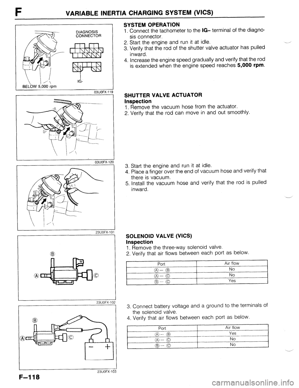
SYSTEM OPERATION
DIAGNOSIS 1. Connect the tachometer to the IG- terminal of the diagno- CONNECTOR sis connector.
2. Start the engine and run it at idle.
3. Verify that the rod of the shutter valve actuator has pulled -
inward.
OSUOFX-I 19
F-118
i-..
1”
03UOFX-I 2
23UOFX-1 C
23UOFX-1 C
23UOFX-IC
4. increase the engine speed gradually and verify that the rod
is extended when the engine speed reaches 5,000 rpm.
SHUTTER VALVE ACTUATOR
Inspection
1. Remove the vacuum hose from the actuator.
2. Verify that the rod can move in and out smoothly.
3. Start the engine and run it at idle.
4. Place a finger over the end of vacuum hose and verify that
there is vacuum.
5. Install the vacuum hose and verify that the rod is pulled
inward.
SOLENOID VALVE (VICS)
Inspection
1. Remove the three-way solenoid valve.
2. Verify that air flows between each port as below.
Port
@--@ - -
@-0
@ --- (g Air flow
No
No
Yes
3. Connect battery voltage and a ground to the terminals of
the solenoid valve.
4. Verify that air flows between each port as below.
Port Air flow
-_I
-I_
@- 03 Yes
@l-o No
@--0 No
Page 385 of 1164
VARIABLE INERTIA CHARGING SYSTEM (VICS) F
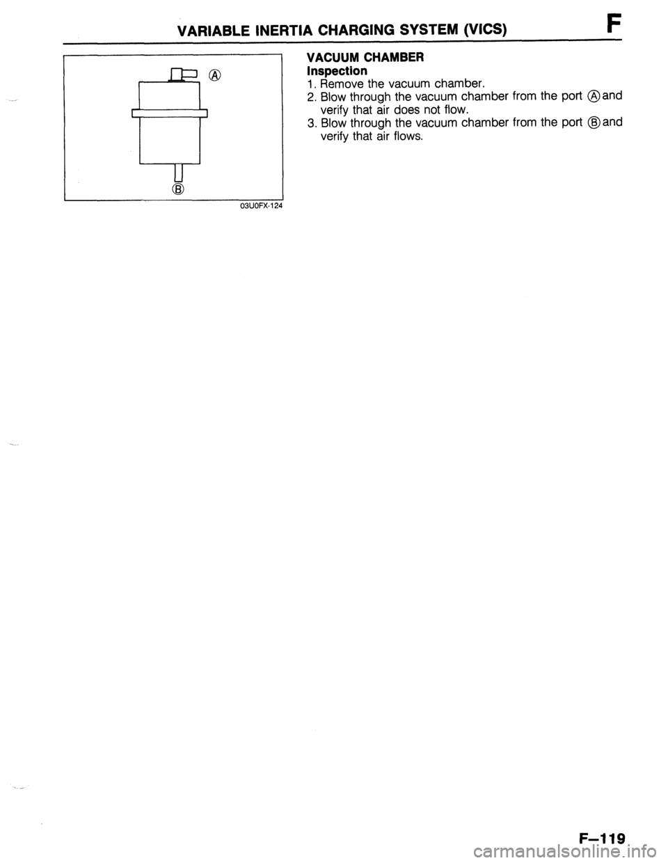
VACUUM CHAMBER
Inspection
1. Remove the vacuum chamber.
2. Blow through the vacuum chamber from the port @and
verify that air does not flow.
3. Blow through the vacuum chamber from the port @and
verify that air flows.
03UOFX-12
F-119
Page 422 of 1164

F CONTROL SYSTEM
Ve: Battery voltage
erminal Input Output Connection to
Test condition Correct voltage Remark
2s 0 Solenoid valve
Engine speed below 5,000 rpm ov VICS: Variable In-
(VICS)
Engine speed above 5,000 rpm
VB ertia Charging
System [DOHC]
2T 0 Solenoid valve
60 [DOHC]/120 [SOHC] seconds after ov
(Pressure regula- engine started when engine coolant tem-
tor) [BP] perature above 90% (194OF) and intake
-
air temperature above 58% (136’F)
[DOHC]/50% (122OF) [SOHC]
Other condition at idle
Ve
2u
0 Injector (Nos. 1, 3) Ignition switch ON V0 *Engine Signal
idle
VB Monitor: Green
Engine speed above 2,000 rpm on de-
VB and red lamps
flash
celeration (After warm-up)
2v 0 Injector (Nos. 2, 4) Ignition switch at idle
Ve
idle
VI3
Engine speed above 2,000 rpm on de-
VB celeration (After warm-up)
2w
0 ISC valve Ignition switch ON Approx. 7V
-
Idle
Approx. QV
2x 0 Solenoid valve Ignition switch ON
VB (Purge control) -
Idle VB
2Y - - - - - -
23UOFX-1:
I r
U----l l-l
Ll I-
2y
2w 2u 2s 20 20 2M 2K 21 23 2E 2C 2.4 1U 1s 10 10 1M 1K 11 1G 1E 1~ IA
2z 2x 2’4 2T 2R 2P 2N 2L 2J 2l-i 2F 2D 28 IV 1T 1R lp IN IL 1J 1~ 1F If) 1~ -/
F-l 56