MAZDA PROTEGE 1992 Workshop Manual
Manufacturer: MAZDA, Model Year: 1992, Model line: PROTEGE, Model: MAZDA PROTEGE 1992Pages: 1164, PDF Size: 81.9 MB
Page 881 of 1164

SWITCHES T
Removal / Installation (Canada without cruise control system)
1. Remove in the order shown in the figure.
2. Install in the reverse order of removal.
1. Horn cap
2. Steering wheel
3. Steering column cover 4. Combination switch
13UOTX-01;
Disassembly / Assembly . . . . . . . . . . . . . page T-26
Inspection . . , . . . . . . . . . . . . . . . . . . . . . . . . . . . ,. . , . page T-28
T-25
Page 882 of 1164

T SWITCHES
Disassembly / Assembly
1. Remove in the order shown in the figure.
2. Install in the reverse order of removal.
I
CANADA WITHOUT CRUISE CONTROL SYSTEM
13UOTX-01 8
1. Cancel cam
2. Spring 3. Wiper lever
4. Light unit -
T-26
Page 883 of 1164

SWITCHES T
I 03UOTX-040
HU
HL BA
E HEAD
BTN
1 BUOTX-01
WITHOUT CRUISE CONTROL SYSTEM
p=j==gz$~
WITH CRUISE CONTROL SYSTEM
03UOTX-042
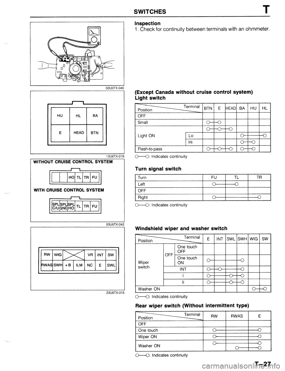
Inspection
1. Check for continuity between terminals with an ohmmeter.
IExcept Canada without cruise control system)
Jght switch
t OFF < BTN E HEAD BA HU HL
Small
Light ON 0 V-0
Lo 0 3
Hi o----o
1 Flash-to-Dass
I-lo-+-oI I
C--Q: Indicates continuity
Turn signal switch
1 Turn 1 FU TL 1 TR
I
I Left
I o-+--o I I
1 OFF
Right
C--O: Indicates continuity 0 I I
0
Windshield wiper and washer switch
Terminal E
INT SWL SWH WIG SW
Wioer
I 1 6N 3 touch
1-01 I
switch I -
INT o--o Q
I
c- o---o
II 0 C----O
Washer ON
I I I I I 0-l-Q 23UOTX-01 O--O: Indicates continuity
Rear wiper switch (Without intermittent type)
O----O: Indicates continuity
T-27
Page 884 of 1164

T SWITCHES
, 23UOTX-016
13UOTX.02
L
TL
FU TR
OBUOTX-I 76
03UOTX-I 7
03uolx17
Rear wiper switch (With intermittent type)
-
Position Terminal RW
RWAS E
OFF
One touch 0 0
Wiper ON 0 0
Washer ON 0 0
O--O: Indicates continuity
(Canada without cruise control system)
Light switch
Light ON Lo 0 0
Hi
Flash-to-pass 0 A
” 0
O--O: Indicates continuity
Turn signal switch
1 Turn FU TL TR
I Left
I o---k-o I I
OFF
Right
OFF 0 0
0 A
-0
o--<>: Indicates continuity
Windshield wiper and washer switch
Wiper
switch One touch
OFF OFF
One touch
ON
INT
L I - I -
I I I (LOW) 0 ) 1 0 1
I I lo-+-al
1 Washer ON I I I IO-+0
o---O: Indicates continuity
Rear wiper switch
r------ -rrr.m;nn, I I I - I RW 1 RWAS I E I
I One touch I c I
Wiper ON 0
0
Washer ON 0 0
0
0
M: Indicates continuity
T-28
Page 885 of 1164

EXTERIOR LIGHTING SYSTEM T
EXTERIOR LIGHTING SYSTEM
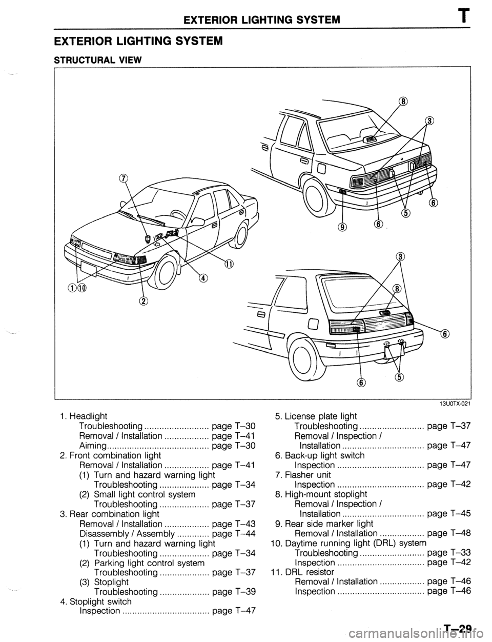
STRUCTURAL VIEW
13UOTX-02
1. Headlight 5. License plate light
Troubleshooting .......................... page T-30 Troubleshooting .......................... page T-37
Removal / Installation .................. page T-41 Removal / Inspection I
Aiming ......................................... page T-30 Installation ................................. page T-47
2. Front combination light 6. Back-up light switch
Removal / Installation .................. page T-41 Inspection ................................... page T-47
(1) Turn and hazard warning light 7. Flasher unit
Troubleshooting .................... page T-34 Inspection ................................... page T-42
(2) Small light control system 8. High-mount stoplight
Troubleshooting .................... page T-37 Removal / Inspection /
3. Rear combination light Installation ................................. page T-45
Removal / Installation .................. page T-43 9. Rear side marker light
Disassembly I Assembly ............. page T-44 Removal / Installation .................. page T-48
(1) Turn and hazard warning light 10. Daytime running light (DRL) system
Troubleshooting .................... page T-34 Troubleshooting .......................... page T-33
(2) Parking light control system Inspection ................................... page T-42
Troubleshooting .................... page T-37 11. DRL resistor
(3) Stoplight Removal I Installation .................. page T-46
Troubleshooting .................... page T-39 Inspection ................................... page T-46
4. Stoplight switch
Inspection ................................... page T-47
T-29
Page 886 of 1164

T
Specifications
Item
Headlight
Front turn signal/Parking light
Stop/Taillight
High mount stoplight
Rear turn signal light
Back-up light
License plate light
Rear side marker light
EXTERIOR LIGHTING SYSTEM
* PROTEGi Number Specification (W) (Bulb trade number)
2 65/45 (9004)
2 27/8 (1157)
2*, 4 (3HB) 27/8 (1157)
1 18.4 (1141)
2 27 (1156)
2 27 (1156)
2 7.5 (89)*, 5 (168) [3HB]
2 3.8 (194)
13lJOTX.022
AIMING
1. Adjust the tire air pressure to specification.
2. Position the unloaded vehicle on a flat, level surface. /----------
03UOTX-046 1 3. Adiust the headlights to meet local regulations. To adjust,
Note
l Adjust, using specification numbers 9H-15V (found
on headlight lens) with a “HOPPY” brand aimer or
equivalent.
I
9MUOTX-148
turk the two adjusting screws.
TROUBLESHOOTING
Headlight
Circuit diagram
T-30
OSUOTX-184
Page 887 of 1164

CANADA lDAYTIME RUNNING LIGHTS
E-2
BATTFRY
UN CONTROL UNIT
G (Fl G/Y IF) G/R IF1
INSTRUMENT INSTRUMENT
CLUSTER Cl USTER
(SECTION C) (SECTION C)
WITH
CRUISE CONTROL ‘HEADL1GHTS E-2
MAIN
BOA
COMBINATION EXCEPT
SWITCH ~~;~~~;ENT/cnNnon
(SECTION cl
(!I
cI 4*0*
r----- ORL CONTROL 7
(SECTION E-31
-02 COMBINATION E-03 HEADLIGHT LH(F) E-04 HEADLIGHT FIti
SWITCH (Fl E-05 HEADLIGHT “Et$
-06 TAILLIGHT “E:;;
Page 888 of 1164

I
EXTERIOR LIGHTING SYSTEM
Headlights do not operate (Low and/or High)
(Without cruise)
I
Turn ON light switch (second position)
I
Check head 30A main fuse Short circuit
0
Confirm battery voltage on R w Repair harness (Main fuse - Combination switch) L
I
0 OK
Confirm battery voltage on R wire (when Low) and/or
R/W wire (when High) of the combination switch Replace the combination switch
Confirm battery voltage on R wire (when Low) and/or
R/W wire (when High) of the headlight Repair harness (Combination switch - Headlight)
I
0
Confirm continuity on B wire of the headlight
Repair harness (Headlight - Body ground)
Burnt out bulb
23UOTX-017 Headlights do not operate (Low and/or High)
I
(With cruise)
I
Turn ON light switch (second position)
Short circuit
0 OK
Confirm battery voltage on W/R wire of the combination switch
I
8) C OK Repair harness (Main fuse - Headlight relay)
I
Replace the headlight relay
1
Repair harness (Headlight relay - Combination switch)
Confirm battery voltage on R wire (when Low) and/or
R/W wire (when High) of combination switch connector Replace the combination switch
1
Q 1 OK
Disconnect headlight connector. Confirm battery voltage
on R wire (when Low) and/or on RIW wire (when High)
of connector
,o OK
Repair harness (Combination switch - Headlight)
1
I
Confirm continuity on B wire of the headlight connector
to ground Repair harness (Headlight - Body ground)
I
T-32
OK _ Replace the bulbs
23UOTX-018
Page 889 of 1164

EXTERIOR LIGHTING SYSTEM T
Headlights either do not operate or are dim Low-High beam or passing flasher does not
J operate
Burnt out bulb or poor grounding J
03UOTX-049 Defective combination switch
03UOTX-050
(Canada) Daytime running lights (DRL) do not operate
Confirm that headlights operate with the light switch ON
(second position) OK
Turn OFF the light switch and turn ON the ignition
switch when parking level pulling
I
Check head 30A main fuse OK
Check DRL resistor OK Repair DRL resistor 10A fuse
Confirm battery voltage on R and L/G wire of the DRL NG
relay Repair harness (Fuse - DRL relay)
I
I
Check the DRL relay
Repair DRL relay
1 OK
Confirm battery voltage on (BRNV) wire of the DRL con-
trol unit NG
Repair harness (DRL relay - DRL control unit) OK
Confirm battery voltage on (L/G) wire of the DRL control NG
unit Repair harness (Rear wiper fuse - DRL control unit) OK
Confirm continuity of (G/R) wire of the DRL control unit x Repair harness (DRL control unit - Parking brake
to ground switch) or check the parking brake switch 1 OK
Confirm continuity on (B) wire of the DRL control unit to
NG
ground Repair harness (DRL control unit ground) OK
-1 NG
Confirm approx. 8V on the DRL resistor Repair harness (DRL control unit - DRL headlight)
I
Confirm battery voltage on (
Confirm approx. 8V on (R/W) wire of the DRL resistor Repair harness (DRL resistor - DRL relay)
Repair harness (DRL control unit - DRL resistor)
23UOTX-019
T-33
Page 890 of 1164

EXTERIOR LIGHTING SYSTEM
Turn and Hazard Warning Light
Circuit diagram
BTURN 6; HAZARD FLASHER LIGHTS F-l
BLUE3 TRADE NUMBER
FRONT TURN: 1157 (27W)
REAR TURN : 1156 (27W)
HAZARD SWITCH
ILLUMINATION LAMP:
REFER TO SECTION I-4
-01 TURN SWITCH (F) F-02 FLASHER UNIT (F)
I=] (++&I+YI [ml
WITH CHlJISE CONTROL
WITHOUT CRUISE
CONTROL
-05 HAZARD SWITCH (I) E-12 REAR TURN L$“1’ E-13 REAR TURN ‘R$-$
B R/B
G
03UOTX-052
T-34