battery capacity MAZDA PROTEGE 1992 Workshop Manual
[x] Cancel search | Manufacturer: MAZDA, Model Year: 1992, Model line: PROTEGE, Model: MAZDA PROTEGE 1992Pages: 1164, PDF Size: 81.9 MB
Page 17 of 1164

CAUTION GI
9MUGIX-032
9MUGIX-029
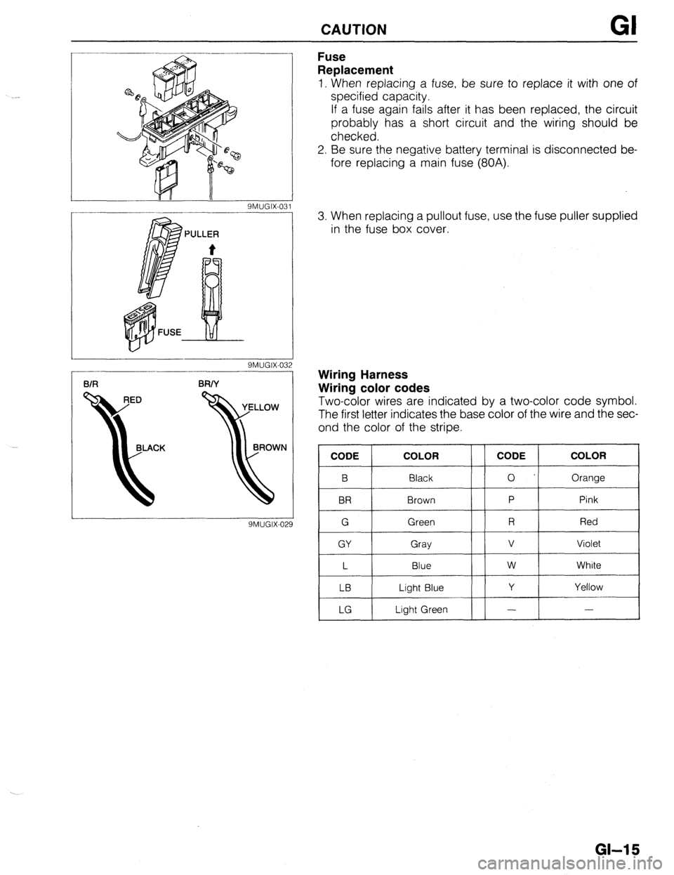
Fuse
Replacement
1. When replacing a fuse, be sure to replace it with one of
specified capacity.
If a fuse again fails after it has been replaced, the circuit
probably has a short circuit and the wiring should be
checked.
2. Be sure the negative battery terminal is disconnected be-
fore replacing a main fuse (80A).
3. When replacing a pullout fuse, use the fuse puller supplied
in the fuse box cover.
Wiring Harness
Wiring color codes
Two-color wires are indicated by a two-color code symbol.
The first letter indicates the base color of the wire and the sec-
ond the color of the stripe.
CODE COLOR
B Black
BR Brown
G Green
GY Gray
L Blue
LB Light Blue
LG Light Green CODE COLOR
0 Orange
P Pink
R Red
v Violet
w White
Y Yellow
- -
GI-15
Page 1064 of 1164

Z-Gl-8 Reading Wiring Diagrams
Svmbols I
Symbol Meaning Symbol Meaning
Battery (I, Generates electricity through Resistance l A resistor with a constant value
chemical reaction l Mainly used to protect electrical
l Supplies direct current to circuits components in circuits by maintaining
rated voltage
l Reading resistance values
Ground (1)
l Connecting point to vehicle body or No.1 Cobr band
-A- other ground wire where current flows -No.2 Cobr band
from positive to negative terminal of -No.3 Cobr band
battery No.4 Cobr band
1
l Ground (1) indicates a ground point to Flnt color. Rerkrancs
body through wire harness
Ground (2) l Gound (2) indicates point where
component is grounded directly to body
Remark
oCurrent wilt not flow through a circuit if
ground is faulty
Fuse (1)
(box)
Fuse (2)
l Melts when current flow exceeds that
specified for circuit, stopping current
flow
Precautions
o Do not replace with fuses exceeding
specified capacity
(Cartridge)
vlain fuse/Fusible
l Electrical switching component
a Turns on when voltage is applied to Motor
0 Converts electrical energy into
mechanical energy
Transistor (2)
coiibmr (Cl
l Reading code l Pulls in and expels gases and liquids
Lamp
Number of terminals O:Low- frequency NPN
l Emits light and generates heat when
Cigarette lighter
current flows through filament a Electrical coil that generates heat
Page 1067 of 1164

Troubleshootina Z-GM 1
Precautions when servicing electrical system
l Note the following items when servicing the electrical system.
l Do not alter the wiring or electrical equipment in any way as this may damage the vehicle or cause a fire
due to shorting or overcapacity of a circuit.
l Always disconnect the negative (- ) battery cable first and 0 Replace blown fuses with ones having the same designated
reconnect It last when disconnecting the battery. capacity.
1OA
15A
Zaution
l Be sure that the ignition and other switches are OFF
before disconnecting or connecting the battery
terminals.
Failure to do so may damage the semi-conductor
components. Caution l Replacing a fuse with one of a larger capacity than
designated may damage components or cause an electrical
fire.
l Secure harnesses with a clamp when provided to take Up l Tape areas of the
a Be sure that the harness
any slack. harness that may rub or
is not caught or damaged
bump against sharp
when mounting
edges to protect it from
components.
damage.
Caution
l Clamp all harnesses near vibrating components(e.g.
the engine) to remove any slack and prevent Contact
due to vibration.
l Do not handle roughly or drop electrical components.
l Disconnect heat sensitive
parts (e.g. relays, ECU)
when performing
maintenance where
temperatures may exceed l Make sure that the
connectors are securely
connected when
installed.
80°C (176°F) (i.e.welding).
oid
Page 1069 of 1164

Troubleshooting Z-Gl-13
el
-
Ill
31
-
I1
Jl
:n
r.
7a
ver
le
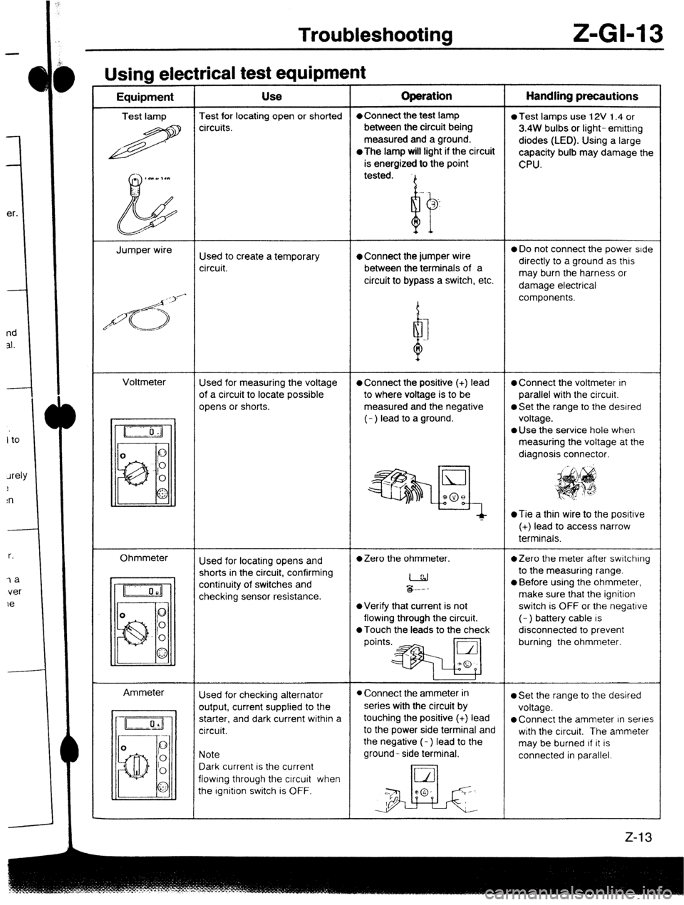
Usina electrical test eaubment -----w - I - Equipment Use Operation Handling precautions
Test lamp Test for locating open or shorted l Connect the test lamp
0 Test lamps use 12V 1.4 or
R circuits. between the circuit being
3.4W bulbs or light- emitting
measured and a ground.
diodes (LED). Using a large
*The
lamp will light if the circuit
capacity bulb may damage the
is energized to the point
CPU.
,.WD,.l
b tested.
Jumper wire
Used to create a temporary l Connect the jumper wire 0 Do not connect the power side
circuit. between the terminals of a directly to a ground as this
circuit to bypass a switch, etc. may burn the harness or
damage electrical
/d<;>‘-
d components.
I
n
Voltmeter
Used for measuring the voltage
l Connect the positive (+) lead l Connect the voltmeter In
of a circuit to locate possible to where voltage is to be parallel with the circuit.
opens or shorts. measured and the negative
0 Set the range to the desired
(- ) lead to a ground. voltage.
l Use the service hole when
measuring the voltage at the
diagnosis connector.
~Tie a thin wire to the posrtive
(+) lead to access narrow
terminals.
Ohmmeter
Ammeter Used for locating opens and
l Zero the ohmmeter. *Zero the meter after switching
shorts in the circuit, confirming
I to the measuring range.
continuity of switches and
checking sensor resistance. &.--
l Before using the ohmmeter,
make sure that the ignition
l Verify that current is not switch is OFF or the negative
flowing through the circuit. (- ) battery cable is
0 Touch the leads to the check disconnected to prevent
points.* burning the ohmmeter.
Used for checking alternator
l Connect the ammeter in l Set the range to the desired
output, current supplied to the series with the circuit by
voltage.
starter, and dark current within a touching the positive (+) lead
l Connect the ammeter in series
circuit. to the power side terminal and
with the circuit. The ammeter
the negative (- ) lead to the
may be burned If it is
Note ground- side terminal.
connected in parallel.
Dark current is the current
flowing through the circuit when
the Ignition switch is OFF.