instrument panel MAZDA PROTEGE 1992 Workshop Manual
[x] Cancel search | Manufacturer: MAZDA, Model Year: 1992, Model line: PROTEGE, Model: MAZDA PROTEGE 1992Pages: 1164, PDF Size: 81.9 MB
Page 831 of 1164

DASHBOARD S
1, Rear ashtray (Without passive IO. Combination switch 18. Glove box lid
shoulder belt) Removal / Installation 19. Lower panel (R.H.)
2. Rear console ,..,,.,......,,.,.,....... Section T 20. Front ashtray
3. Front console 11. Center upper hole cover 21. Lower panel (Center)
4. Control box center cover 12. Upper garnish
22. Glove box cover
(With small front console) 13. Side panel 23. Dash board
5. Side walls 14. Hood release knob Removal Note . . page S-95
6. Undercover 15. Lower panel (L.H.) Installation Note page S-96
7. Steering column 16. Meter hood 24. Pipe frame (Lower)
Removal / Installation 17. Instrument cluster 25. Pipe frame (Upper)
. . . . . . . . ...*. . . . . ..n..... Section N Removal I Installation
1 suosx-017
8. Key cylinder set ring
9. Column cover
JOINT BOX
. . . . . . . . . . . . . . . . . . . . . . . . . . Section T
Removal Note
Dashboard
1, Remove the control wires of the heater unit and blower unit.
2. Disconnect the necessary harness connectors.
s-95
Page 859 of 1164

INDEX T
INSTRUMENT CLUSTER AND SWITCHES
23UOTX-00
1. Rear window defroster switch
7. Fuel gauge sender unit
Inspection
........................... page T-21 Removal / Installation ..................
page T-73
2. Remote control door mirror switch
Inspection ................................... page T-73
Inspection
........................... page T-20 8. Hazard warning switch
3. Ignition switch
Removal / installation .................. page T-20
Removal / Installation..
........ page T-20 Inspection ................................... page T-21
Inspection ........................... page
T-2 1 9. Cruise control main switch
4. Combination switch Inspection ...................................
page T-21
Removal / installation
.......... pages T-23, 25 10. Cruise control switch
Disassembly / Assembly ..... pages T-24, 26 Removal / Installation ..................
page T-20
Inspection
........................... pages T-27, 28 Inspection ................................... page T-21
5. Instrument cluster 11. Power window main switch
Troubleshooting..
................ page T-65 Inspection ................................... page T-22
Removal / Installation
.......... page T-69 12. Power window switch
Disassembly I Assembly ..... page T-70 Inspection ................................... page T-22
Inspection
........................... page T-71 13. Panel lamp control switch
6. Water thermosensor
Inspection ................................... page T-22
Removal / Installation..
........ page T-72
Inspection ........................... page T-72
T-3
Page 870 of 1164

T FUSE AND JOINT BOX
Specifications (Cont’d)
Fuse Color
METER 15A Blue
WIPER 20A Yellow
STOP 20A Yellow
TAIL 15A
Blue
SUNROOF 15A Blue
DEFOG 20A Yellow
HEATER 30A Light green Protected circuit Instrument panel (gauges and warning lamps), Back-up light, Turn signal,
Cruise control system
Windshield wiper and washer
Stoplight, Horn
Taillight, Side marker light, Parking light, Illumination light, License plate light
Sunroof
Rear window defroster
Blower motor
13UOTX-067
L
r 03UOTX-01
1 BL
PULLER
t
L 03UOTX-01
CIRCUIT
BREAKER
RESET BUTTON
03UOTX.01
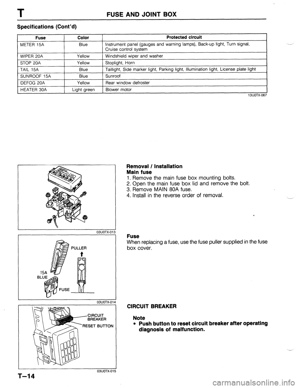
Removal / Installation
Main fuse
1. Remove the main fuse box mounting bolts.
2. Open the main fuse box lid and remove the bolt.
3. Remove MAIN 80A fuse.
4. Install in the reverse order of removal.
Fuse
When replacing a fuse, use the fuse puller supplied in the fuse
box cover.
CIRCUIT BREAKER
Note
l Push button to reset circuit breaker after operating
dlagnosls of malfunction.
5
T-14
Page 955 of 1164

AUDIO T
97UOTX-If
13UOTX-06
/-cl/ /
03UOTX-18:
03UOTX-16 OWOTX-189
6
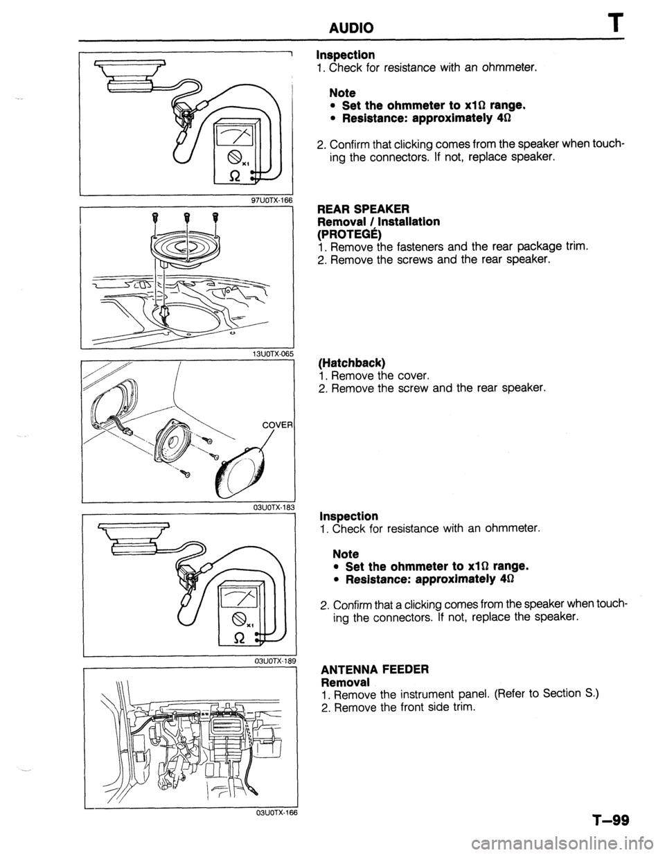
Inspection
1. Check for resistance with an ohmmeter.
Note
l Set the ohmmeter to xl0 range.
l Redstance: approximately 4h2
2. Confirm that clicking comes from the speaker when touch-
ing the connectors. If not, replace speaker.
REAR SPEAKER
Removal / Installation
(PROTEGe)
1. Remove the fasteners and the rear package trim.
2. Remove the screws and the rear speaker.
(Hatchback)
1. Remove the cover.
2. Remove the screw and the rear speaker.
Inspection
1. Check for resistance with an ohmmeter.
Note
l Set the ohmmeter to xl0 range.
l Resistance: approximately 43
2. Confirm that a clicking comes from the speaker when touch-
ing the connectors. If not, replace the speaker.
ANTENNA FEEDER
Removal
1. Remove the instrument panel. (Refer to Section S.)
2. Remove the front side trim.
T-99
Page 994 of 1164

U
COOLING UNIT
Removal / Installation AIR CONDITIONER
1. Discharge the refrigeration system. (Refer to page U-32.)
2. Remove the glove box, glove box cover, undercover, and instrument panel stay. (Refer to Section S.)
3. Remove the cooling unit as shown in the figure. -
Note
l Immediately plug all open fittings to keep moisture out of system.
4. Install the cooling unit in the reverse order of removal.
Note
l Position the cooling unit so that its connections match those of the heater unit and blower unit.
l Apply clean compressor oil to the O-rings before connecting the fittings.
l Do not apply compressor oil to the fitting nuts.
l When installing a new cooling unit, add compressor oil through the high-pressure pipe port
of the compressor.
Compressor oil: 50 cc (3.05 cu in)
Tightening torque
Outlet pipe: 20-29 N*m (2.0-3.0 m-kg, 14-22 ft-lb)
lnla+ nina. Q n,7n N.m (I -0-2.0 m&a. 7,7-IA ftJh IIllcvb yap”. “.” -1 . . . . . \..’ -_- __- ..~, JII .- .I .-,
23UOUX-0: -.,
1. Cooling unit
Disassembly / Assembly.. . . . . . . . . . . . page U-39
U-38
Page 1050 of 1164

PARTS INDEX
I
CRANKSHAFT.. ....................................
I31 -64
CYLINDER BLOCK .............................. 61-60
CYLINDER HEAD..
............................... 81-54
CYLINDER HEAD GASKET .................
Bl-16
DRIVE BELT(S). ...................................... 81-5
FRONT OIL SEAL ................................ 81-23
HLA .............................................. Bl-7,20,60
OIL JET ................................................ 81-61
PISTON.. ...............................................
Bl-62
PISTON PIN..
........................................ 81-62
PISTON RING
....................................... 81-62
REAR
OIL SEAL..
................................. 81-25
TENSIONER, IDLER ............................. Bl-65
TENSIONER
SPRING ...........................
Bl-65
TIMING BELT ..................................
Bl-12,65
TIMING BELT PULLEY ........................
Bl-65
VALVE MECHANISM ........................... Bl-55
ENGINE
(BP DOHC) .................................... B2-2
CAMSHAFT ..........................................
82-58
CAMSHAFT PULLEY ...........................
B2-65
CONNECTING ROD..
........................... 82-63
CRANKSHAFT ......................................
B2-64
CYLINDER BLOCK ..............................
82-60
CYLINDER
HEAD.. ............................... B2-54
CYLINDER HEAD GASKET .................
82-16
DRIVE
BELTS.. .......................................
B2-5
FRONT
OIL SEAL ................................
82-26
H LA ..............................................
OIL JET .......................... B2-7iyL;;
......................
PISTON .................................................
B2-62
PISTON PIN ..........................................
82-62
PISTON RING..
..................................... 82-62
REAR OIL SEAL ................................... B2-28
TENSIONER, IDLER ............................. B2-65
TENSIONER SPRING ........................... B2-65
TIMING
BELT.. ................................
B2-12,65
TIMING BELT PULLEY ........................ 82-65
VALVE MECHANISM ........................... 82-55
ENGINE CONTROL UNIT (ECU) ............... F-149
ENGINE COOLANT
........................................ E-5
ENGINE OIL.. .................................................
D-7
ENGINE OIL FILTER.. .................................... D-8
’ EXHAUST SYSTEM. ...................................
F-136
EXTRACTOR CHAMBER .............................. S-53
F
FAN MOTOR (COOLING FAN). ................... E-14
FAN RELAY (COOLING FAN). ..................... E-18
FLASHER UNIT ............................................
T-17
FLOORMAT ..................................................
S-99
FLYWHEEL ..................................................
H-18
FRONT AXLE .................................................
M-4
FRONT BRAKE ............................................
P-l 8
FRONT BUMPER ......................................... S-39
FRONT DOOR ................................................
S-8
FRONT DOOR LOCK AND OPENER ..........
S-13
PI-2
FRONT FENDER PANEL ............................... S-7
FRONT LOWER ARM .................................. R-16
FRONT SHOCK ABSORBER AND SPRING R-11
FRONT SIDE WINDOW REGULATOR AND
GLASS ........................................................ S-10
FRONT STABILIZER..
................................... R-l 8
FRONT SUSPENSION .................................. R-l 0
FUEL FILLER LID AND OPENER..
.............. S-37
FUEL FILTER .............................................. F-l 24
FUEL GAUGE SENDER UNIT ..................... T-73
FUEL PUMP ............................................... F-125
FUEL TANK
................................................ F-123
FUSE AND JOINT BOX.. .............................. T-12
H
HEADLIGHT AND
FRONT COMBINATION LIGHT..
................ T-41
HEADLIGHT RELAY ..................................... T-l 8
HEADLINER ................................................. S-89
HEATER CONTROL UNIT.. ......................... U-26
HEATER UNIT
.............................................. U-21
HIGH-MOUNT STOPLIGHT
.......................... T-45
HIGH-TENSION LEAD ................................. G-l 7
HOOD ............................................................. S-5
HORN T-88
...........................................................
HORN RELAY
.......................................... T-18,88
.__. ’
I I
IGNITER .......................................................
G-23
IGNITION COIL.. .......................................... G-19
INJECTOR .................................................. F-l 31
INSTRUMENT CLUSTER
AND SPEEDOMETER CABLE
.................... T-69
INTAKE MANIFOLD ................................... F-113
INTERIOR LAMP ..................................... T-52,53
ISC VALVE.. ................................................ F-l 16
J
JOINT SHAFT (FRONT AXLE) .................... M-18
L
LATERAL LINK AND TRAILING LINK.. ....... R-26
LICENSE PLATE LIGHT.. ............................. T-47
i
M
I
---
MAIN RELAY (FUEL INJ. RELAY). ............ F-172
MANUAL STEERING ..................................... N-4
MANUAL TRANSAXLE (F5M-R). .................. Jl-2
Page 1063 of 1164

Reading Wiring Diagrams Z-GI-7
HARNESS SYMBOLS
DESCRIPTION OF HARNESS
FRONT HARNESS
ENGINE HARNESS
INSTRUMENT PANEL HARNESS
REAR HARNESS
REAR NO.2 HARNE COLOR SYMBOL DESCRIPTION OF HARNESS SYMBOL
(F) INTERIOR LAMP HARNESS (IN)
(El FLOOR HARNESS
FW
(1) DOOR NO.1 HARNESS Ml)
DOOR NO.2 HARNESS
WW
EMISSION HARNESS AIR CONDITIONER HARNESS
INSTRUMENT PANEL HARNESS
FRONT HARNESS [a ,&<\I INJECTION HARNESS [INJ]
EMISSION’ HARNESS (EM)
I ENGINE HARNESS [E]
/
EMISSION HARNESS (EM)
INTERlOq IAMP HARNESS [IN]
- INTERlO? LAMP HARNESS [IN]
SUNRGOF GESS [SU]
REAR HklNESS [R]
323 HATCHBACK
IARNESS (R3)
FL00F4 HAdNEss(FR1 -,A HARNESS (Rl DOOR NO.3 HARNESS [DRS]
PROTE&
Page 1074 of 1164

: WIRINQ DIAQRAM
l GROUND POINT
Y WIRING ORDER INTO JOINT CONNECTOR MAY BE CHANGED
JC-0
1 JOINT CONNECTOR (F) JC-02 JOINT CONNECTOR (F) JC-03 JOINT CONNECTOR (F)
r-9 6-l e-7 e-l r-l r-l
B B 8 B B B B B B B B B B B B
JC-04 JOINT CONNECTOR (EM) JC-06 JOINT CONNECTOR (EM1 JC-09 XICIIN; CONNECTOR (R)
m -
B B B B B
JC-12 JOINT CONNECTOR (R)
(PROTEGE) JC-13 JOINT CONNECTOR (R)
(PROTEGE)
EMISSION
INSTRUMENT PANEL
Page 1075 of 1164

HARNESS COLOR :
FRONT m
INSTRUMENT PANEL!“.:“-“. REAR ENGIN-
WIRING’ DIAGRAM 2
I
JC-13
Page 1119 of 1164

____ -.-.a -.a--..* 7
HARNESS HOLIER : F,W’,T~ ENGINE- INSTRUMENT PANEL: ,-’ AEAR - WIRINU IJlAIiliAM L
I
F (WITH CRUISE COWROL)
TURN SWITCH .JoiNT
CONNECTOR
I
%%I3 UNIT
F-02
JOINT Box JOINT BOX
@L, J%-06
/ JB-04 FRONT TURN JB I FUSE BOX
,E;,‘,?uRN LIGHT LH
PROTEGE m :ki%RN LIGHT LH
7-m -