ignition MAZDA PROTEGE 1992 Workshop Manual
[x] Cancel search | Manufacturer: MAZDA, Model Year: 1992, Model line: PROTEGE, Model: MAZDA PROTEGE 1992Pages: 1164, PDF Size: 81.9 MB
Page 3 of 1164
GENERAL INFORMATION
IMPORTANT INFORMATION ..................... GI- 2
BASIC ASSUMPTIONS ............................ GI- 2
SAFETY RISK ........................................ GI- 2
POSSIBLE LOSS OF WARRANTY ............. GI- 2
WARNING ON LUBRICANTS
AND GREASES .................................... GI- 2
HOW TO USE THIS MANUAL.. .................. GI- 3
PREPARATION ...................................... GI- 3
REPAIR PROCEDURE ............................. GI- 3
SYMBOLS ............................................. GI- 4
NOTES, CAUTIONS, AND WARNINGS.. ..... GI- 4
FUNDAMENTAL PROCEDURES.. ............... GI- 4
PROTECTION OF THE VEHICLE .............. GI- 4
A WORD
ABOUT SAFETY ....................... GI- 5
PREPARATION OF TOOLS
AND MEASURING EQUIPMENT.. ........... GI- 5
SPECIAL TOOLS .................................... GI- 5
REMOVAL OF PARTS ............................. GI- 5
DISASSEMBLY ...................................... GI- 5
REASSEMBLY ....................................... GI- 6
ADJUSTMENTS ..................................... GI- 7
RUBBER
PARTS AND TUBING ................
GI- 7
JACK AND SAFETY STAND POSITIONS.. .. GI- 6
VEHICLE LIFT (P-SUPPORT TYPE)
POSITIONS ............................................ GI- 6
TOWING .................................................. GI- 9
IDENTIFICATION NUMBER LOCATIONS ..... 61-10
UNITS ..................................................... GI-10
ABBREVIATIONS ..................................... GI-10
CAUTION ................................................ GI-1 1
INSTALLATION OF MOBILE
TWO-WAY RADIO SYSTEM .................... GI-11
REMOVAL OF IGNITION KEY ON
AUTOMATIC TRANSAXLE MODEL.. ........
GI-1 1
ELECTRICAL TROUBLESHOOTING TOOLS GI-12
CAUTION WITH ELECTRICAL PARTS ........
GI-13
03UGIX-001
Page 11 of 1164
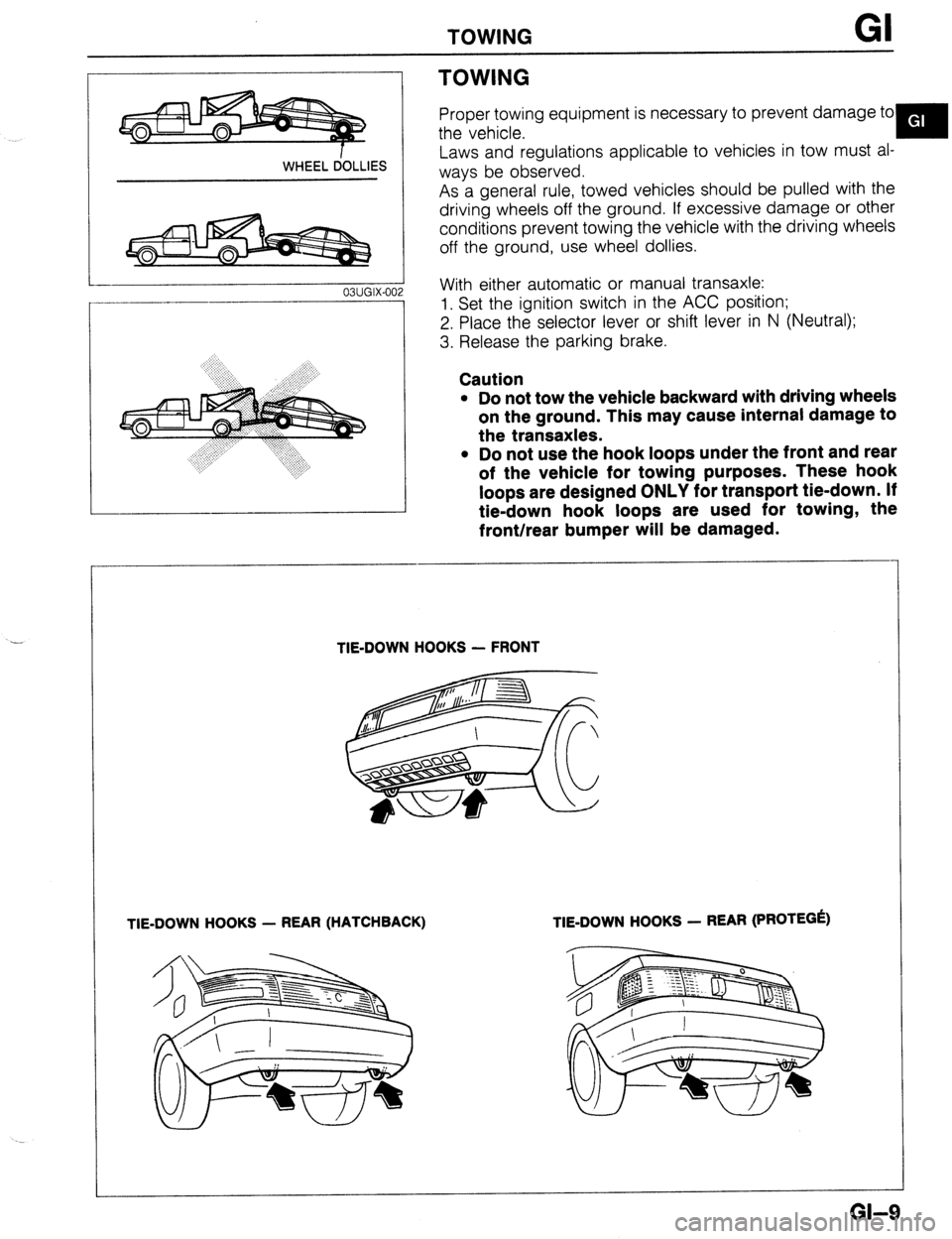
TOWING
.-
WHEEL dOLLlES
03UGIX-00
TOWING
Proper towing equipment is necessary to prevent damage to
the vehicle.
Y
Laws and regulations applicable to vehicles in tow must al-
ways be observed.
As a general rule, towed vehicles should be pulled with the
driving wheels off the ground. If excessive damage or other
conditions prevent towing the vehicle with the driving wheels
off the ground, use wheel dollies.
With either automatic or manual transaxle:
1. Set the ignition switch in the ACC position;
2. Place the selector lever or shift lever in N (Neutral);
3. Release the parking brake.
Caution
l Do not tow the vehicle backward with driving wheels
on the ground. This may cause internal damage to
the transaxles.
l Do not use the hook loops under the front and rear
of the vehicle for towing purposes. These hook
loops are designed ONLY for transport tie-down. If
tie-down hook loops are used for towing, the
front/rear bumper will be damaged.
TIE-DOWN HOOKS - FRONT
TIE-DOWN HOOKS - REAR (HATCHBACK) TIE-DOWN HOOKS - REAR (PROTEGk)
GI-9
Page 12 of 1164
GI IDENTIFICATION NUMBER LOCATIONS/UNITS/ABBREVlATlONS
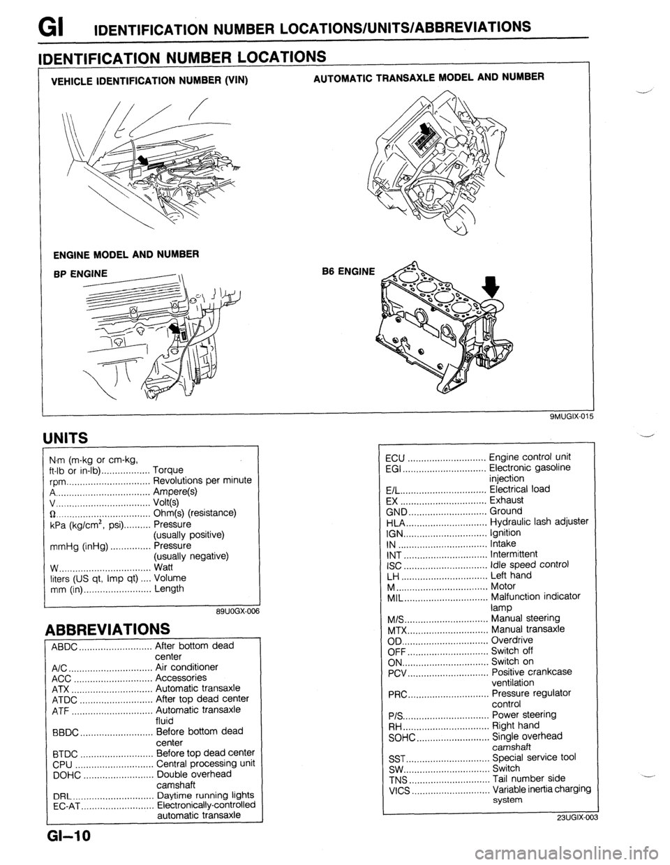
VEHICLE IDENTIFICATION NUMBER (VIN) AUTOMATIC TRANSAXLE MODEL AND NUMBER
ENGINE MODEL AND NUMBER
B6 ENGINE
IDENTIFICATION NUMBER LOCATIONS
UNITS
I
N.m (m-kg or cm-kg,
ft-lb or in-lb) . . . . . . . . . . . . . . . . . . Torque
rpm ._..,,,.............,.......... Revolutions per minute
A . . . . . . . . . . . . . . . . . Ampere(s)
v, . . . . . . . . . . . . . .
Volt(s)
$2 _....._..,......................... Ohm(s) (resistance)
kPa (kg/cm2,
psi) . . . . . . . . . . Pressure
(usually positive)
mmHg (inHg) . . . . . . . . . . . . . . . Pressure
(usually negative)
W.. . . . . . . . . . . .
Watt
liters (US qt, Imp qt) ,... Volume
mm (in) ..,......,...,........... Length
89UOGX-00
ABBREVIATIONS
ABDC . . . . . . . . . . . . . . . . . . . . .
After bottom dead
center
A/C . . . . . . . . . . . . . . . . . . . . . . . . . . . . . . .
Air conditioner
ACC ..,.,...... 3 . . . . . . . . . . . . . . . . . Accessories
ATX . . . . . . . . . . . . . . . . . . . . . . . . . . . . . . Automatic transaxle
ATDC ..,,...,...,............... After top dead center
ATF . . . . . . . . . . . . . . . . . Automatic transaxle
fluid
BBDC ,,..,.......,...,......,... Before bottom dead
center
BTDC .,......,...............,.. Before top dead center
CPU ..,,.......,...,..........,.. Central processing unit
DOHC ..,...,..,............,,.. Double overhead
camshaft
DRL ____.......................... Daytime running lights
EC-AT .,_.......,............,,.. Electronically-controlled
automatic transaxle
L
GI-10
ECU ............................. Engine control unit
EGI ............................... Electronic gasoline
injection
E/L.. .............................. Electrical load
EX ................................ Exhaust
GND.. ........................... Ground
HLA.. ............................ Hydraulic lash adjuster
IGN ............................... Ignition
IN ................................. Intake
INT ............................... Intermittent
ISC
............................... idle speed control
LH ................................ Left hand
M..
................................ Motor
MIL..
............................. Malfunction indicator
lamp
M/S..
............................. Manual steering
MTX.. ............................ Manual transaxle
OD ................................ Overdrive
OFF.. ............................ Switch off
ON.. .............................. Switch on
PCV.. ............................ Positive crankcase
ventilation
PRC..
............................ Pressure regulator
control
PIS ................................ Power steering
RH..
.............................. Right hand
SOHC.. .........................
z;;kiprhead
SST ............................... Special service tool
SW.. .............................. Switch
TNS
.............................. Tail number side
VICS
............................. Variable inertia charging
system
23UGIX-00
Page 13 of 1164
CAUTION GI
CAUTION
INSTALLATION OF MOBILE TWO-WAY RADIO SYSTEM
If a mobile two-way radio system is installed improperly or if a high-powered type is used, the EGI system
and other systems may be affected.
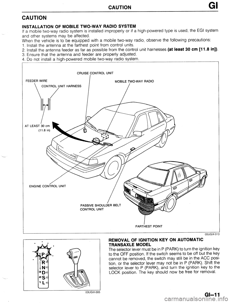
When the vehicle is to be equipped with a mobile two-way radio, observe the following precautions:
1. Install the antenna at the farthest point from control units.
2. Install the antenna feeder as far as possible from the control unit harnesses (at least 30 cm [11.8 in]).
3. Ensure that the antenna and feeder are properly adjusted.
4. Do not install a high-powered mobile two-way radio system.
CRUISE CONTROL UNIT
FEEDER WIRE
I MOBILE TWO-WAY RADIO
CONTROL UNIT HARNESS
/ /
4T LEAST b0
cm
(11.8 in)
OWGIX-013 ENGINE CONiROL UNIT
/
FARTiEST POINT
REMOVAL OF IGNITION KEY ON AUTOMATIC
TRANSAXLE MODEL
The selector lever must be in P (PARK) to turn the ignition key
to the OFF position. If the switch seems to be off but the key
cannot be removed, the switch may still be in the ACC posi-
tion, or the selector lever may not be in P (PARK). Shift the
selector lever to P (PARK), and turn the ignition key to the
LOCK position. The key should now be free for removal.
GI-1 1
Page 20 of 1164
PRE-DELIVERY INSPECTION
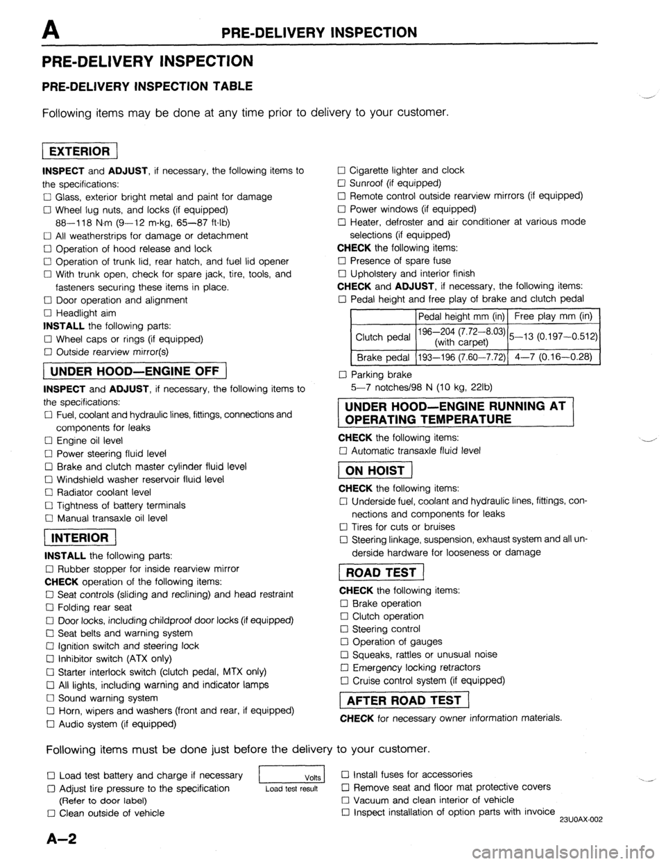
PRE-DELIVERY INSPECTION
PRE-DELIVERY INSPECTION TABLE
Following items may be done at any time prior to delivery to your customer.
INSPECT and ADJUST, if necessary, the following items to
the specifications:
0 Glass, exterior bright metal and paint for damage
Cl Wheel lug nuts, and locks (if equipped)
88-118 N.m (9-12 m-kg, 65-87 ft-lb)
q All weatherstrips for damage or detachment
0 Operation of hood release and lock
0 Operation of trunk lid, rear hatch, and fuel lid opener
Cl With trunk open, check for spare jack, tire, tools, and
fasteners securing these items in place.
Cl Door operation and alignment
Cl Headlight aim
INSTALL the following parts:
Cl Wheel caps or rings (if equipped)
q Outside rearview mirror(s)
1 UNDER HOOD-ENGINE OFF )
INSPECT and ADJUST, if necessary, the following items to
the specifications:
0 Fuel, coolant and hydraulic lines, fittings, connections and
components for leaks
Cl Engine oil level
0 Power steering fluid level
0 Brake and clutch master cylinder fluid level
El Windshield washer reservoir fluid level
Cl Radiator coolant level
Cl Tightness of battery terminals
Cl Manual transaxle oil level
riizmiq
INSTALL the following parts:
Cl Rubber stopper for inside rearview mirror
CHECK operation of the following items:
0 Seat controls (sliding and reclining) and head restraint
Cl Folding rear seat
0 Door locks, including childproof door locks (if equipped)
Seat belts and warning system
Cl Ignition switch and steering lock
0 Inhibitor switch (ATX only)
U Starter interlock switch (clutch pedal, MTX only)
Cl All lights, including warning and indicator lamps
Cl Sound warning system
Cl Horn, wipers and washers (front and rear, if equipped)
0 Audio system (if equipped) 0 Cigarette lighter and clock
0 Sunroof (if equipped)
II Remote control outside rearview mirrors (if equipped)
Cl Power windows (if equipped)
q Heater, defroster and air conditioner at various mode
selections (if equipped)
CHECK the following items:
Cl Presence of spare fuse
0 Upholstery and interior finish
CHECK and ADJUST, if necessary, the following items:
0 Pedal height and free play of brake and clutch pedal
Pedal height mm (in) Free play mm (in)
0 Parking brake
5-7 notches/98 N (10 kg, 22lb)
UNDER HOOD-ENGINE RUNNING AT
OPERATING TEMPERATURE
CHECK the following items:
q Automatic transaxle fluid level
[I
CHECK the following items:
Cl Underside fuel, coolant and hydraulic lines, fittings, con-
nections and components for leaks
0 Tires for cuts or bruises
0 Steering linkage, suspension, exhaust system and all un-
derside hardware for looseness or damage
[I
CHECK the following items:
0 Brake operation
0 Clutch operation
Cl Steering control
Cl Operation of gauges
q Squeaks, rattles or unusual noise
Cl Emergency locking retractors
0 Cruise control system (if equipped)
1 AFTER ROAD TEST (
CHECK for necessary owner information materials.
Following items must be done just before the delivery to your customer.
q Load test battery and charge if necessary
1 Volts 1 0 Install fuses for accessories
i.. _
0 Adjust tire pressure to the specification
Load test result cl Remove seat and floor mat protective covers
(Refer to door label) 0 Vacuum and clean interior of vehicle
0 Clean outside of vehicle q Inspect installation of option parts with invoice
23UOAX-002
A-2
Page 31 of 1164
Bl
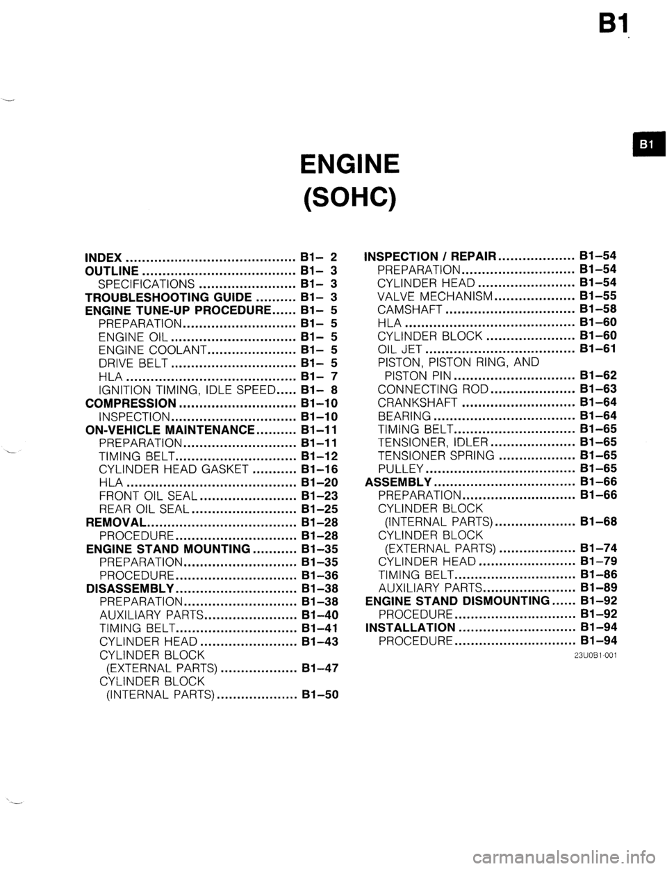
ENGINE
(SOHC)
INDEX .......................................... Bl- 2
OUTLINE ...................................... Bl- 3
SPECIFICATIONS ........................
Bl- 3
TROUBLESHOOTING GUIDE ..........
Bl- 3
ENGINE TUNE-UP PROCEDURE ......
Bl- 5
PREPARATION ............................ Bl- 5
ENGINE OIL ............................... Bl- 5
ENGINE COOLANT.. ....................
Bl- 5
DRIVE BELT ............................... Bl- 5
HLA .......................................... Bl- 7
IGNITION TIMING, IDLE SPEED
..... Bl- 8
COMPRESSION ............................. Bl-10
INSPECTION ............................... 81-10
ON-VEHICLE
MAINTENANCE.. ........
Bl-1 1
PREPARATION ............................ Bl-11
TIMING BELT .............................. Bl-12
CYLINDER
HEAD GASKET ........... Bl-16
HLA .......................................... Bl-20
FRONT OIL SEAL.. ...................... 81-23
REAR OIL SEAL ..........................
Bl-25
REMOVAL ..................................... 81-28
PROCEDURE .............................. Bl-28
ENGINE STAND MOUNTING.. .........
Bl-35
PREPARATION
............................ 81-35
PROCEDURE ..............................
Bl-36
DISASSEMBLY .............................. Bl-38
PREPARATION ............................ Bl-38
AUXILIARY PARTS.. ..................... 81-40
TIMING BELT .............................. 81-41
CYLINDER HEAD.. ......................
81-43
CYLINDER BLOCK
(EXTERNAL PARTS)
................... 81-47
CYLINDER BLOCK
(INTERNAL
PARTS). ................... Bl-50 INSPECTION /
REPAIR.. .................
81-54
PREPARATION ............................ Bl-54
CYLINDER HEAD.. ...................... Bl-54
VALVE
MECHANISM.. .................. Bl-55
CAMSHAFT ................................ 81-58
HLA .......................................... Bl-60
CYLINDER BLOCK ......................
Bl-60
OIL JET ..................................... Bl-61
PISTON, PISTON RING, AND
PISTON PIN .............................. Bl-62
CONNECTING ROD.. ...................
Bl-63
CRANKSHAFT ............................ Bl-64
BEARING ................................... 81-64
TIMING BELT .............................. Bl-65
TENSIONER,
IDLER.. ................... 81-65
TENSIONER SPRING ...................
81-65
PULLEY ..................................... Bl-65
ASSEMBLY ................................... Bl-66
PREPARATION ............................ Bl-66
CYLINDER BLOCK
(INTERNAL PARTS). ................... Bl-68
CYLINDER BLOCK
(EXTERNAL PARTS) ...................
Bl-74
CYLINDER
HEAD.. ...................... 81-79
TIMING BELT .............................. Bl-86
AUXILIARY
PARTS.. ..................... Bl-89
ENGINE STAND DISMOUNTING.. .... Bl-92
PROCEDURE .............................. 81-92
INSTALLATION ............................. 81-94
PROCEDURE .............................. Bl-94
23UOBl-001
Page 33 of 1164
OUTLINE, TROUBLESHOOTING GUIDE Bl
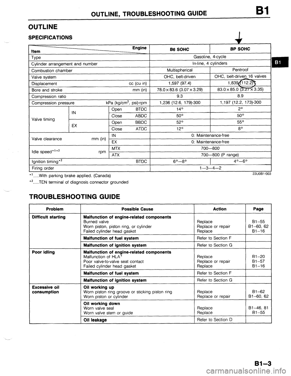
OUTLINE
SPECIFICATIONS
item Engine
Type
Cylinder arrangement and number
Combustion chamber
Valve system
Displacement cc (cu in)
Bore and stroke mm (in)
Compression ratio
Compression pressure
kPa (kg/cm2, psi)-rpm
Open BTDC
IN
Close ABDC
Valve timing
EX Open
BBDC
Close ATDC
IN
Valve clearance
mm (in)
EX
Idle speed*‘*’ MTX
rpm ATX
Ignition timing*2
BTDC
Firing order
*‘.....With parking brake applied. (Canada)
*‘.....TEN terminal of diagnosis connector grounded B6 SOHC BP SOHC
Gasoline, 4-cycle
in-line, 4 cylinders
Multispherical Pentroof
OHC, belt-driven OHC, belt-driven 16 valves
1,597 (97.4) 1,839&i 12.23
78.0 x 83.6 (3.07 x 3.29) 83.0x 85.0 -3.35)
9.3 8.9
1,236 (12.6, 179)300 1,197 (12.2, 173)-300
140 2O
50° 5o”
52O 55O
120 8
0: Maintenance-free
0: Maintenance-free
700-800
700-800 (P range)
6O----8O 4O--6O
1-3-4-2
23UOBl-003
TROUBLESHOOTING GUIDE
Problem
Difficult starting
Poor idling
Excessive oil
consumption Possible Cause
Malfunction of engine-related components
Burned valve
Worn piston, piston ring, or cylinder
Failed cvlinder head aasket Action Page
Replace 81-55
Replace or repair 81-60, 62
Reolace Bl-16
Malfunction of fuel system
1 Refer to Section F
I
Malfunction of ignition system
Malfunction of engine-related components
Malfunction of HLA*
Poor valve-to-valve seat contact
Failed cvlinder head aasket Refer to Section G
Replace
Replace or repair
Reolace 81-20
81-57
81-16
Malfunction of fuel system 1 Refer to Section F
I
Malfunction of ignition system Refer to Section G
Oil working up
Worn piston ring groove or sticking piston ring
Worn piston or cylinder
Oil working down
Worn valve seal
Worn valve stem or wide Replace
Replace or repair
Replace
Replace 81-62
Bl-60, 62
81-46, 81
81-55
Oil leakage Refer to Section D
81-3
Page 34 of 1164
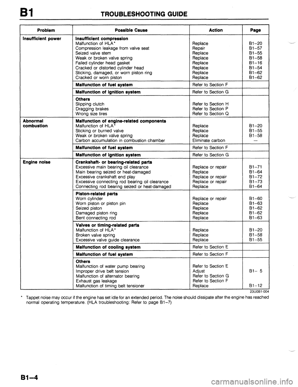
Bl TROUBLESHOOTING GUIDE
Problem
Insufficient power
Abnormal
combustion
Engine noise Possible Cause
Insufficient compression
Malfunction of HLA*
Compression leakage from valve seat
Seized valve stem
Weak or broken valve spring
Failed cylinder head gasket
Cracked or distorted cylinder head
Sticking, damaged, or worn piston ring
Cracked or worn piston Malfunction of fuel system
Malfunction of ignition system
Others
Slipping clutch
Dragging brakes
Wrong size tires Malfunction of engine-related components
Malfunction of HLA’
Sticking or burned valve
Weak or broken valve spring
Carbon accumulation in combustion chamber Malfunction of fuel system
Malfunction of ignition system
Crankshaft- or bearing-related parts
Excessive main bearing oil clearance
Main bearing seized or heat-damaged
Excessive crankshaft end play
Excessive connecting rod bearing oil clearance
Connecting rod bearing seized or heat-damaged Piston-related parts
Worn cylinder
Worn piston or piston pin
Seized piston
Damaged piston ring
Bent connecting rod Valves or timing-related parts
Malfunction of HLA*
Broken valve spring
Excessive valve guide clearance Malfunction of cooling system
Malfunction of fuel system
Others
Malfunction of water pump bearing
Improper drive belt tension
Malfunction of alternator bearing
Exhaust gas leakage
Malfunction of timing belt tensioner Action
Replace
Repair
Replace
Replace
Replace
Replace
Replace
Replace
Refer to Section F
Refer to Section G
Refer to Section H
Refer to Section P
Refer to Section Q
Replace
Replace
Replace
Eliminate carbon
Refer to Section F
Refer to Section G
Replace or repair
Replace
Replace or repair
Replace or repair
Replace
Replace or repair
Replace
Replace
Replace
Replace
Replace
Replace
Replace
Refer to Section E
Refer to Section F
Refer to Section E
Adjust
Refer to Section G
Refer to Section F
Replace Page 81-20
Bl-57
81-55
81-58
81-16
81-54
81-62
al-62
81-20
81-55
81-58
-
61-71
Bl-64
81-72
81-73 8-i-64
Bl-60
81-63
81-62
81-62
El-63
Bl-20
El-58
81-55
Bl- 5
81-12
911 IORI .N)J LI.,“l. --
* Tappet noise may occur if the engine has set idle for an extended period. The noise should
normal operating temperature. (HLA troubleshooting: Refer to page Bl-7) dissipate after the engine has reached
81-4
Page 38 of 1164
Bl ENGINE TUNE-UP PROCEDURE
13UOBi-036
-i
OWOBX-261
13UOBl-08
LOCK BOLTS
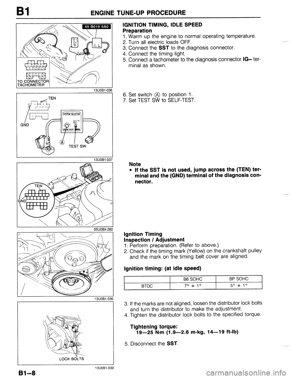
IGNITION TIMING, IDLE SPEED
Preparation
1, Warm up the engine to normal operating temperature.
2. Turn all electric loads OFF.
3. Connect the
SST to the diagnosis connector.
4. Connect the timing light.
5. Connect a tachometer to the diagnosis connector
IG- ter-
minal as shown.
6. Set switch @ to position 1.
7. Set TEST SW to SELF-TEST.
Note
l If the SST is not used, jump across the (TEN) ter-
minal and the (GND) terminal of the diagnosis con-
nector.
Ignition Timing
Inspection / Adjustment
1. Perform preparation. (Refer to above.)
2. Check if the timing mark (Yellow) on the crankshaft pulley
and the mark on the timing belt cover are aligned.
Ignition timing: (at idle speed)
B6 SOHC
BTDC 70 f 10 BP SOHC
5O f lo
3. If the marks are not aligned, loosen the distributor lock bolts
and turn the distributor to make the adjustment.
4. Tighten the distributor lock bolts to the specified torque.
Tightening torque:
19-25 N.m (1.9-2.6 m-kg, 14-19 ft-lb)
5. Disconnect the SST.
Bl-8
13UOBl-039
Page 40 of 1164
Bl COMPRESSION
COMPRESSION
If the engine exhibits low power, poor fuel economy, or poor idle, check the following:
1. Ignition system (Refer to Section G.)
2. Compression
3. Fuel system (Refer to Section F.)
23UOBl-01
23UOBl-06
23UOBl-014 23UOBl-012
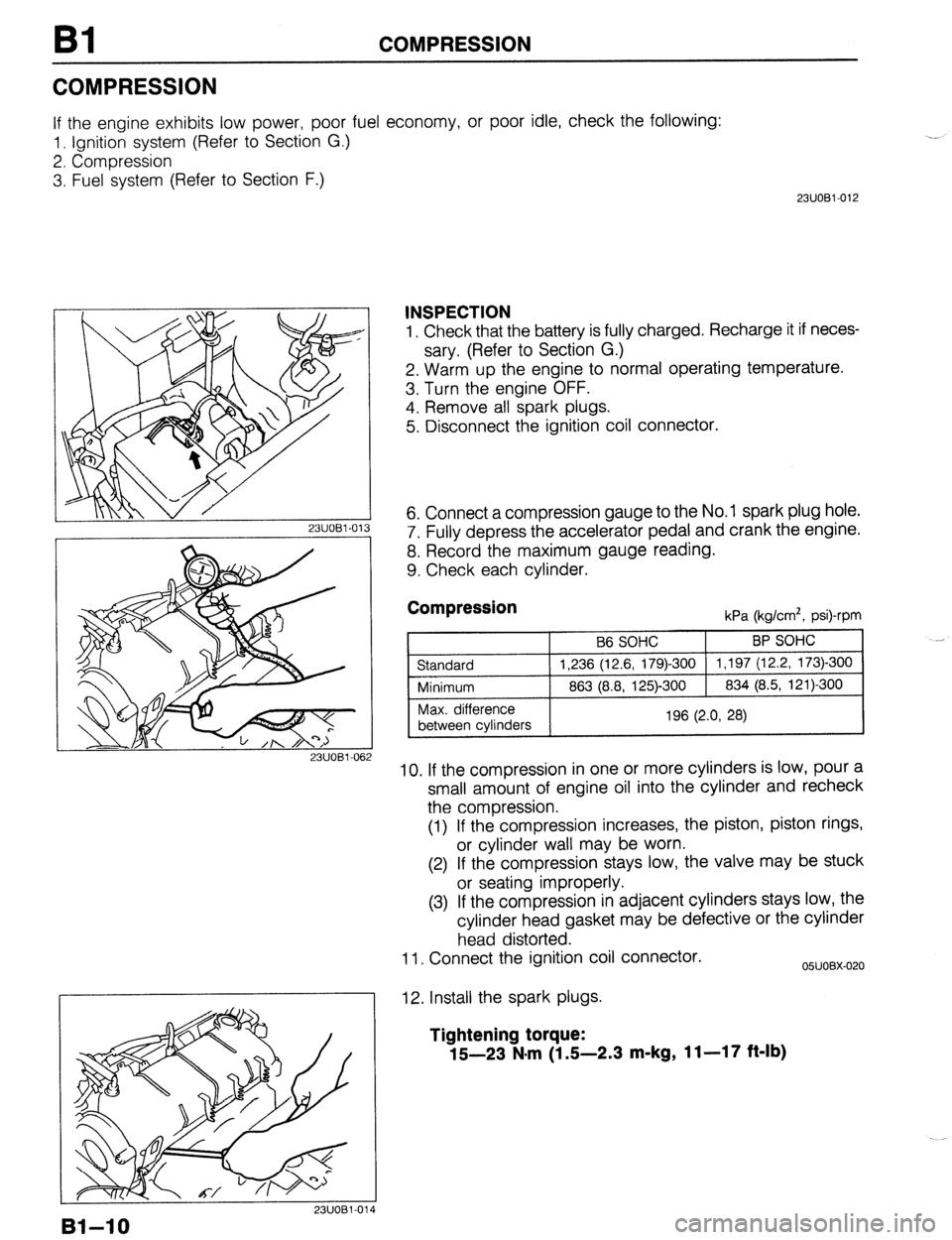
INSPECTION
1. Check that the battery is fully charged. Recharge it if neces-
sary. (Refer to Section G.)
2. Warm up the engine to normal operating temperature.
3. Turn the engine OFF.
4. Remove all spark plugs.
5. Disconnect the ignition coil connector.
6. Connect a compression gauge to the No. 1 spark plug hole.
7. Fully depress the accelerator pedal and crank the engine.
8. Record the maximum gauge reading.
9. Check each cylinder.
Compression kPa (kg/cm*, psi)-rpm
10. If the compression in one or more cylinders is low, pour a
small amount of engine oil into the cylinder and recheck
the compression.
(1) If the compression increases, the piston, piston rings,
or cylinder wall may be worn.
(2) If the compression stays low, the valve may be stuck
or seating improperly.
(3) If the compression in adjacent cylinders stays low, the
cylinder head gasket may be defective or the cylinder
head distorted.
11. Connect the ignition coil connector.
12. Install the spark plugs.
05UOBX-020
Tightening torque:
15-23 N*m (1 S-2.3 m-kg, 11-17 ft-lb)
Bl-10