turn signal MAZDA PROTEGE 1992 Workshop Manual
[x] Cancel search | Manufacturer: MAZDA, Model Year: 1992, Model line: PROTEGE, Model: MAZDA PROTEGE 1992Pages: 1164, PDF Size: 81.9 MB
Page 283 of 1164

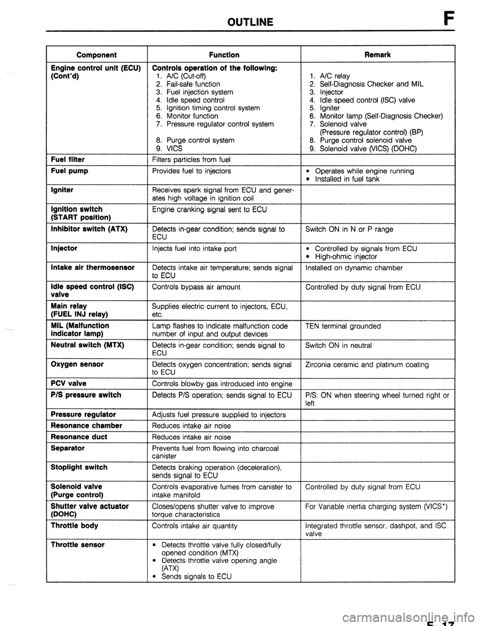
OUTLINE
Component Function Remark
Engine control unit (ECU) Controls operation of the following:
(Cont’d)
1. A/C (Cut-off) 1. A/C relay
2. Fail-safe function 2. Self-Diagnosis Checker and MIL
3. Fuel injection system 3. Injector
4. idle speed control 4. Idle speed control (ISC) valve
5. Ignition timing control system 5. Igniter
6. Monitor function 6. Monitor lamp (Self-Diagnosis Checker)
7. Pressure regulator control system 7. Solenoid valve
(Pressure regulator control) (BP)
8. Purge control system 8. Purge control solenoid valve
9. VICS 9. Solenoid valve (WCS) (DOHC) Fuel filter
Filters particles from fuel Fuel pump
Provides fuel to injectors l Operates while engine running l Installed in fuel tank Igniter
Receives spark signal from ECU and gener-
ates high voltage in ignition coil Ignition switch
Engine cranking signal sent to ECU (START position)
Inhibitor switch (ATX)
Detects in-gear condition; sends signal to Switch ON in N or P range
ECU Injector
Intake air thermosensor
Idle speed control (ISC)
valve
Main relay
(FUEL INJ relay)
MIL (Malfunction
indicator lamp)
Neutral switch (MTX)
Oxygen sensor
PCV valve
P/S pressure switch
Pressure regulator
Resonance chamber
Resonance duct
Separator
Stoplight switch
Solenoid valve
(Purge control)
Shutter valve actuator
(DOHC)
Throttle body
Throttle sensor
Injects fuel into intake port l Controlled by signals from ECU
l High-ohmic injector
Detects intake air temperature; sends signal Installed on dynamic chamber
to ECU
Controls bypass air amount Controlled by duty signal from ECU
Supplies electric current to injectors, ECU,
etc.
Lamp flashes to indicate malfunction code
number of input and output devices
Detects in-gear condition; sends signal to
ECU
Detects oxygen concentration; sends signal
to ECU
Controls blowby gas introduced into engine
Detects P/S operation; sends signal to ECU
Adjusts fuel pressure supplied to injectors
Reduces intake air noise
Reduces intake air noise
Prevents fuel from flowing into charcoal
canister
Detects braking operation (deceleration),
sends signal to ECU
Controls evaporative fumes from canister to
intake manifold
Closes/opens shutter valve to improve
torque characteristics
Controls intake air quantity
l Detects throttle valve fully closed/fully
opened condition (MTX) TEN terminal grounded
Switch ON in neutral
Zirconia ceramic and platinum coating
P/S: ON when steering wheel turned right or
left
Controlled by duty signal from ECU
For Variable inertia charging system (VICS*)
Integrated throttle sensor, dashpot, and ISC
valve
l Detects throttle valve opening angle
(A-W
l Sends signals to ECU
F-l 7
Page 348 of 1164

F SELF-DIAGNOSIS FUNCTION
SELF-DIAGNOSIS FUNCTION
DESCRIPTION
The engine control unit (integrated with the EC-AT control unit) has built-in Self-Diagnosis function the same
as for the previous models. When trouble occurs in the main input devices or output devices, they are indi-
cated and retrieved from the engine control unit (ECU) as service code numbers.
When inspecting for service code(s) memorized in the ECU use the Self-Diagnosis checker and system selector
(SST).
Note
l The ECU constantly checks for malfunction of the in put devices. But, the ECU checks for
malfunction of output devices only in a three second period after the ignition switch is turned
ON and the TEN terminal of the diagnosis connector is grounded.
-
-
INPUT =
SIGNALS-
-
-
- SELF-
DIAGNOSTIC
L!
I-
FUNCTION ENGINE CONTROL
UNIT
j FAIL-SAFE
FUNCTION
I
SYSTEM SELF-DIAGNOSIS
SELECTOR
CHECKER
MIL
(MALFUNCTION
INDICATOR LAMP)
Page 351 of 1164

SELF-DIAGNOSIS FUNCTION F
:ODE LOCATION OF
NO.
MALFUNCTION
26 Solenoid valve ON
(purge control)
OFF OUTPUT SIGNAL PATTERN nnnnnll 1 SELF4IAGNOSIS
Open or
short circuit FAIL-SAFE
-
ON
34
ISC valve
OFF u 1 llllJlll r -
41 Solenoid valve ON
(WCS)
[DOHC]
OFF -
Pulse ON No input signal Shifting performed in
55*
i nnnnn
from pulse accordance with signals
generator
OFF generator from vehicle speed
sensor
Open or Solenoid valve(s)
60* 1-2 shift ON
short circuit
solenoid valve
uuuuul performs the shifting with
as little interference as
OFF
possible with driving
performance
2-3 shift ON Lockup not provided
61*
solenoid valve
OFF
UUUI n
3-4 shift ON
62’
solenoid valve
OFF u u u u inn
1.6 sec. 4 sec.
63* Lockup solenoid
valve
u u&m I- Shifting performed
normally
Lockup not provided
0.4 sec.
0.4 sec.
*If the marked code numbers appeor, refer to Section K
Note
l The HOLD indicator does not flash the service code numbers.
l If there is more than one failure present, the code numbers will be indicated in numerical or-
der, lowest number first.
* After repairing a problem, turn the ignition switch OFF and disconnect the negative battery
cable at least 20 seconds to erase the service code numbers from the engine control unit (ECU)
memory.
23UOFX-051
F-85
Page 867 of 1164

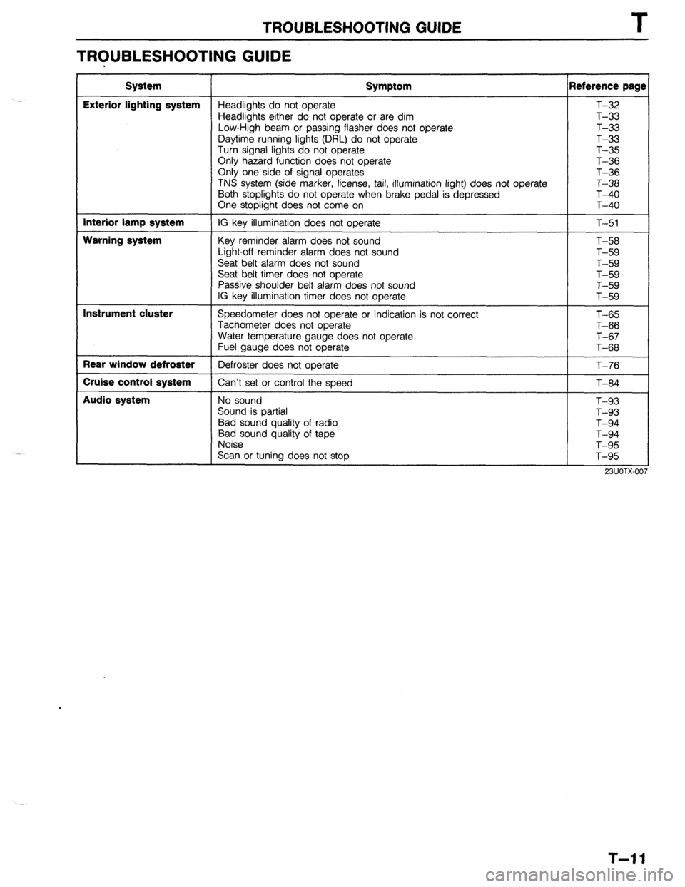
TROUBLESHOOTING GUIDE T
TROUBLESHOOTING GUIDE
System
Exterior lighting system
Interior lamp system
Warning system
Instrument cluster
Rear window defroster
Cruise control system
Audio system Symptom Reference page
Headlights do not operate T-32
Headlights either do not operate or are dim T-33
Low-High beam or passing flasher does not operate T-33
Daytime running lights (DRL) do not operate T-33
Turn signal lights do not operate T-35
Only hazard function does not operate T-36
Only one side of signal operates
T-36
TNS system (side marker, license, tail, illumination light) does not operate T-38
Both stoplights do not operate when brake pedal is depressed T-40
One stoplight does not come on T-40
IG key illumination does not operate
T-51
Key reminder alarm does not sound
Light-off reminder alarm does not sound
Seat belt alarm does not sound
Seat belt timer does not operate
Passive shoulder belt alarm does not sound
IG key illumination timer does not operate T-58
T-59
T-59
T-59
T-59
T-59
Speedometer does not operate or indication is not correct
Tachometer does not operate
Water temperature gauge does not operate
Fuel gauge does not operate
Defroster does not operate
Can’t set or control the speed T-65
T-66
T-67
T-68
T-76
T-84
No sound
Sound is partial
Bad sound quality of radio
Bad sound quality of tape
Noise
Scan or tuning does not stop T-93
T-93
T-94
T-94
T-95
T-95
T-l 1
Page 870 of 1164

T FUSE AND JOINT BOX
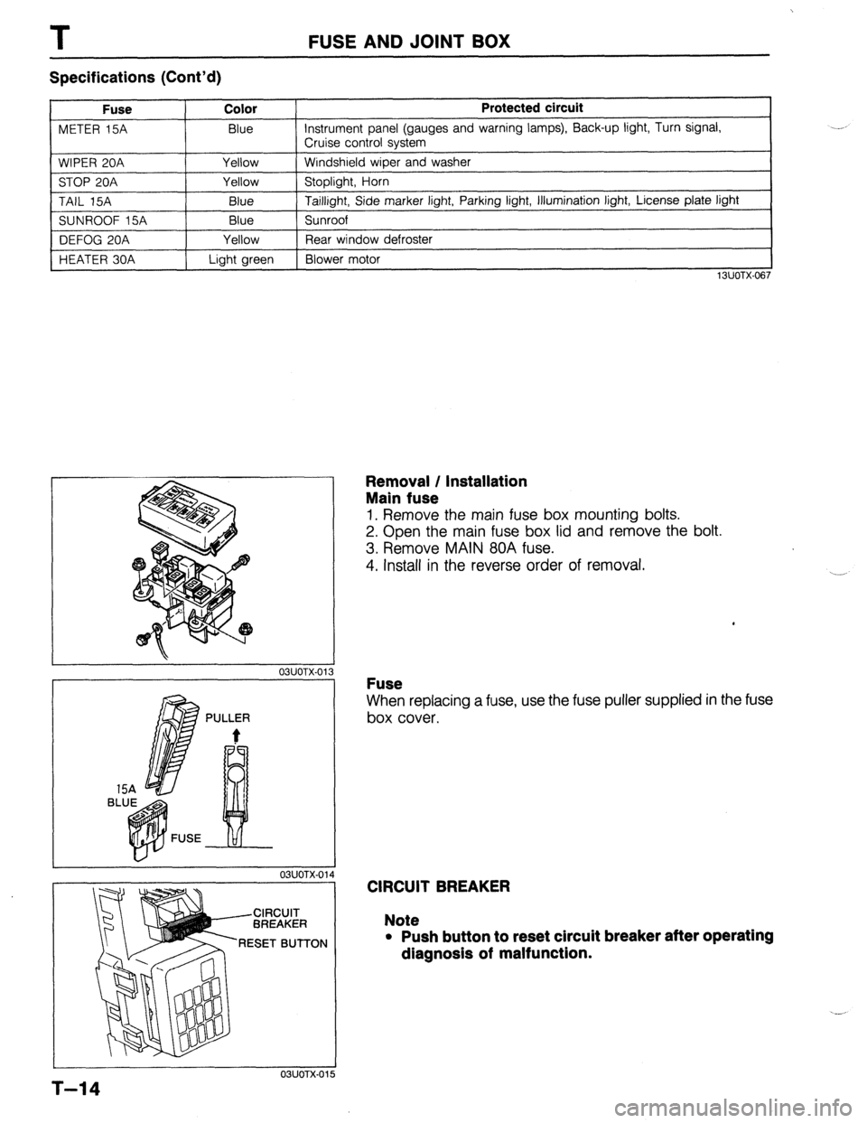
Specifications (Cont’d)
Fuse Color
METER 15A Blue
WIPER 20A Yellow
STOP 20A Yellow
TAIL 15A
Blue
SUNROOF 15A Blue
DEFOG 20A Yellow
HEATER 30A Light green Protected circuit Instrument panel (gauges and warning lamps), Back-up light, Turn signal,
Cruise control system
Windshield wiper and washer
Stoplight, Horn
Taillight, Side marker light, Parking light, Illumination light, License plate light
Sunroof
Rear window defroster
Blower motor
13UOTX-067
L
r 03UOTX-01
1 BL
PULLER
t
L 03UOTX-01
CIRCUIT
BREAKER
RESET BUTTON
03UOTX.01
Removal / Installation
Main fuse
1. Remove the main fuse box mounting bolts.
2. Open the main fuse box lid and remove the bolt.
3. Remove MAIN 80A fuse.
4. Install in the reverse order of removal.
Fuse
When replacing a fuse, use the fuse puller supplied in the fuse
box cover.
CIRCUIT BREAKER
Note
l Push button to reset circuit breaker after operating
dlagnosls of malfunction.
5
T-14
Page 883 of 1164

SWITCHES T
I 03UOTX-040
HU
HL BA
E HEAD
BTN
1 BUOTX-01
WITHOUT CRUISE CONTROL SYSTEM
p=j==gz$~
WITH CRUISE CONTROL SYSTEM
03UOTX-042
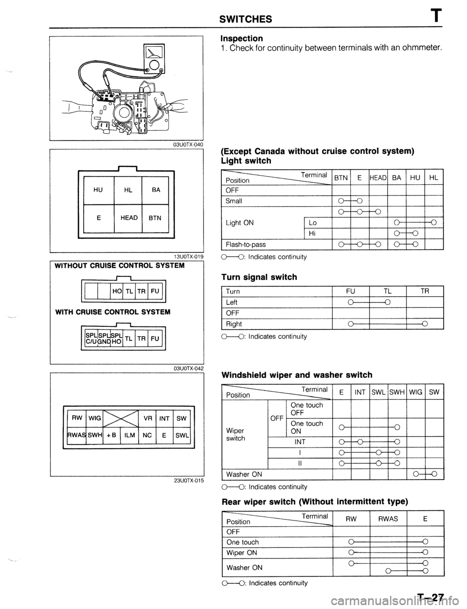
Inspection
1. Check for continuity between terminals with an ohmmeter.
IExcept Canada without cruise control system)
Jght switch
t OFF < BTN E HEAD BA HU HL
Small
Light ON 0 V-0
Lo 0 3
Hi o----o
1 Flash-to-Dass
I-lo-+-oI I
C--Q: Indicates continuity
Turn signal switch
1 Turn 1 FU TL 1 TR
I
I Left
I o-+--o I I
1 OFF
Right
C--O: Indicates continuity 0 I I
0
Windshield wiper and washer switch
Terminal E
INT SWL SWH WIG SW
Wioer
I 1 6N 3 touch
1-01 I
switch I -
INT o--o Q
I
c- o---o
II 0 C----O
Washer ON
I I I I I 0-l-Q 23UOTX-01 O--O: Indicates continuity
Rear wiper switch (Without intermittent type)
O----O: Indicates continuity
T-27
Page 884 of 1164

T SWITCHES
, 23UOTX-016
13UOTX.02
L
TL
FU TR
OBUOTX-I 76
03UOTX-I 7
03uolx17
Rear wiper switch (With intermittent type)
-
Position Terminal RW
RWAS E
OFF
One touch 0 0
Wiper ON 0 0
Washer ON 0 0
O--O: Indicates continuity
(Canada without cruise control system)
Light switch
Light ON Lo 0 0
Hi
Flash-to-pass 0 A
” 0
O--O: Indicates continuity
Turn signal switch
1 Turn FU TL TR
I Left
I o---k-o I I
OFF
Right
OFF 0 0
0 A
-0
o--<>: Indicates continuity
Windshield wiper and washer switch
Wiper
switch One touch
OFF OFF
One touch
ON
INT
L I - I -
I I I (LOW) 0 ) 1 0 1
I I lo-+-al
1 Washer ON I I I IO-+0
o---O: Indicates continuity
Rear wiper switch
r------ -rrr.m;nn, I I I - I RW 1 RWAS I E I
I One touch I c I
Wiper ON 0
0
Washer ON 0 0
0
0
M: Indicates continuity
T-28
Page 886 of 1164

T
Specifications
Item
Headlight
Front turn signal/Parking light
Stop/Taillight
High mount stoplight
Rear turn signal light
Back-up light
License plate light
Rear side marker light
EXTERIOR LIGHTING SYSTEM
* PROTEGi Number Specification (W) (Bulb trade number)
2 65/45 (9004)
2 27/8 (1157)
2*, 4 (3HB) 27/8 (1157)
1 18.4 (1141)
2 27 (1156)
2 27 (1156)
2 7.5 (89)*, 5 (168) [3HB]
2 3.8 (194)
13lJOTX.022
AIMING
1. Adjust the tire air pressure to specification.
2. Position the unloaded vehicle on a flat, level surface. /----------
03UOTX-046 1 3. Adiust the headlights to meet local regulations. To adjust,
Note
l Adjust, using specification numbers 9H-15V (found
on headlight lens) with a “HOPPY” brand aimer or
equivalent.
I
9MUOTX-148
turk the two adjusting screws.
TROUBLESHOOTING
Headlight
Circuit diagram
T-30
OSUOTX-184
Page 891 of 1164

EXTERIOR LIGHTING SYSTEM
Turn Signal lights do not operate
Check meter 15A fuse A an
I
0 OK
Confirm battery voltage on BI Repair harness (Fuse - Turn switch) OK
1 ~,-
Check the turn signal switch NG
(Refer to page T-27 or T-28) Replace the turn switch
1 OK
Turn ignition switch to ON. Turn the signal switch to
RIGHT or LEFT
Confirm battery voltage on G or Y wire of the flasher
unit Repair harness (Turn switch - Flasher unit)
6) OK
Confirm battery voltage on B Repair harness (Fuse - Flasher unit)
1
1 OK
Check the flasher unit (Refe Replace the flasher unit
I
(B OK
Confirm battery voltage on G/W (G/B) wire of the turn
signal light NG _
Repair harness (Flasher unit - Turn signal light) @ OK
Confirm continuity on B wire of the turn signal light to
ground OK
Replace the bulb NG
Repair harness (Turn signal light - Body ground)
23UOTX-020
T-35
Page 892 of 1164

I
EXTERIOR LIGHTING SYSTEM
Only hazard function does not operate
Check the hazard warning Replace the hazard switch
1 I
1 OK
Confirm continuity on B wire of the hazard switch to
ground Repair harness (Hazard switch - Body ground)
OK
I I
Push the hazard switch to activate
OK -2
Confirm continuity on B wire of the flasher unit to body
ground NG
Repair harness (Flasher unit - Hazard switch)
OK
NG
Check the flasher unit (Refer
Replace the flasher unit
Normal
I
Only one side of signal operates
13UOTX-026 .,
Check the turn signal switch
(Refer to page T-27 or T-28)
I Replace the turn switch
1 OK
Turn ignition switch to ON. Turn the signal switch to
defective side
Repair harness (Turn switch - Flasher unit)
Replace the flasher unit
Confirm battery voltage on G/W (G/B) wire of the turn
signal light NG-
- Repair harness (Flasher unit - Turn signal light)
I OK
Confirm continuity on B wire of the turn signal light to
ground NG
Repair harness (Turn signal light - Body ground)
Replace the bulb
T-36
I OK
23UOTX-021