battery MAZDA PROTEGE 1992 Workshop Manual
[x] Cancel search | Manufacturer: MAZDA, Model Year: 1992, Model line: PROTEGE, Model: MAZDA PROTEGE 1992Pages: 1164, PDF Size: 81.9 MB
Page 15 of 1164
. .-
CAUTION Gl
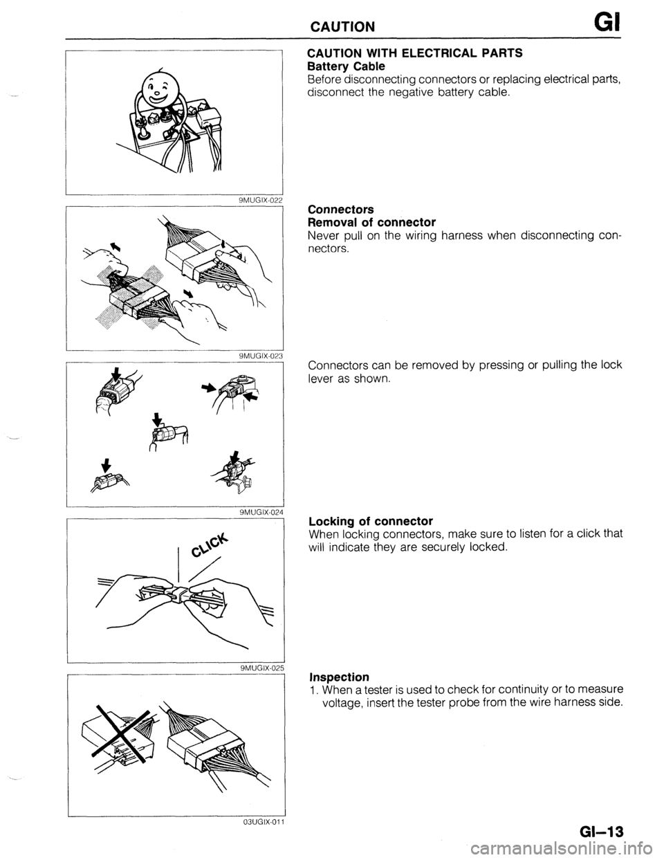
CAUTION WITH ELECTRICAL PARTS
Battery Cable
Before disconnecting connectors or replacing electrical parts,
disconnect the negative battery cable.
SMUGIX-022
YMUGIX-023
SMUGIX-02
SMUGIX-02
03UGIX-011 Connectors
Removal of connector
Never pull on the wiring harness when disconnecting con-
nectors.
Connectors can be removed by pressing or pulling the lock
lever as shown.
Locking of connector
When locking connectors, make sure to listen for a click that
will indicate they are securely locked.
Inspection
1. When a tester is used to check for continuity or to measure
voltage, insert the tester probe from the wire harness side.
GM 3
Page 17 of 1164
CAUTION GI
9MUGIX-032
9MUGIX-029
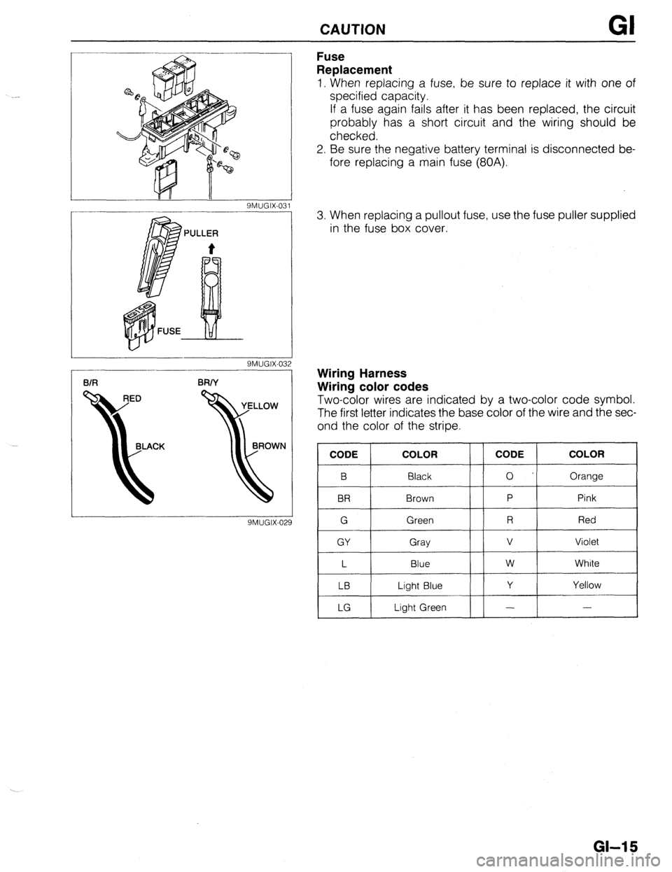
Fuse
Replacement
1. When replacing a fuse, be sure to replace it with one of
specified capacity.
If a fuse again fails after it has been replaced, the circuit
probably has a short circuit and the wiring should be
checked.
2. Be sure the negative battery terminal is disconnected be-
fore replacing a main fuse (80A).
3. When replacing a pullout fuse, use the fuse puller supplied
in the fuse box cover.
Wiring Harness
Wiring color codes
Two-color wires are indicated by a two-color code symbol.
The first letter indicates the base color of the wire and the sec-
ond the color of the stripe.
CODE COLOR
B Black
BR Brown
G Green
GY Gray
L Blue
LB Light Blue
LG Light Green CODE COLOR
0 Orange
P Pink
R Red
v Violet
w White
Y Yellow
- -
GI-15
Page 20 of 1164
PRE-DELIVERY INSPECTION
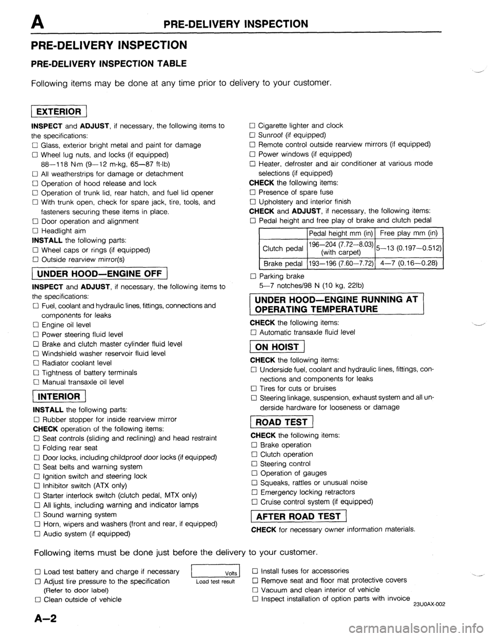
PRE-DELIVERY INSPECTION
PRE-DELIVERY INSPECTION TABLE
Following items may be done at any time prior to delivery to your customer.
INSPECT and ADJUST, if necessary, the following items to
the specifications:
0 Glass, exterior bright metal and paint for damage
Cl Wheel lug nuts, and locks (if equipped)
88-118 N.m (9-12 m-kg, 65-87 ft-lb)
q All weatherstrips for damage or detachment
0 Operation of hood release and lock
0 Operation of trunk lid, rear hatch, and fuel lid opener
Cl With trunk open, check for spare jack, tire, tools, and
fasteners securing these items in place.
Cl Door operation and alignment
Cl Headlight aim
INSTALL the following parts:
Cl Wheel caps or rings (if equipped)
q Outside rearview mirror(s)
1 UNDER HOOD-ENGINE OFF )
INSPECT and ADJUST, if necessary, the following items to
the specifications:
0 Fuel, coolant and hydraulic lines, fittings, connections and
components for leaks
Cl Engine oil level
0 Power steering fluid level
0 Brake and clutch master cylinder fluid level
El Windshield washer reservoir fluid level
Cl Radiator coolant level
Cl Tightness of battery terminals
Cl Manual transaxle oil level
riizmiq
INSTALL the following parts:
Cl Rubber stopper for inside rearview mirror
CHECK operation of the following items:
0 Seat controls (sliding and reclining) and head restraint
Cl Folding rear seat
0 Door locks, including childproof door locks (if equipped)
Seat belts and warning system
Cl Ignition switch and steering lock
0 Inhibitor switch (ATX only)
U Starter interlock switch (clutch pedal, MTX only)
Cl All lights, including warning and indicator lamps
Cl Sound warning system
Cl Horn, wipers and washers (front and rear, if equipped)
0 Audio system (if equipped) 0 Cigarette lighter and clock
0 Sunroof (if equipped)
II Remote control outside rearview mirrors (if equipped)
Cl Power windows (if equipped)
q Heater, defroster and air conditioner at various mode
selections (if equipped)
CHECK the following items:
Cl Presence of spare fuse
0 Upholstery and interior finish
CHECK and ADJUST, if necessary, the following items:
0 Pedal height and free play of brake and clutch pedal
Pedal height mm (in) Free play mm (in)
0 Parking brake
5-7 notches/98 N (10 kg, 22lb)
UNDER HOOD-ENGINE RUNNING AT
OPERATING TEMPERATURE
CHECK the following items:
q Automatic transaxle fluid level
[I
CHECK the following items:
Cl Underside fuel, coolant and hydraulic lines, fittings, con-
nections and components for leaks
0 Tires for cuts or bruises
0 Steering linkage, suspension, exhaust system and all un-
derside hardware for looseness or damage
[I
CHECK the following items:
0 Brake operation
0 Clutch operation
Cl Steering control
Cl Operation of gauges
q Squeaks, rattles or unusual noise
Cl Emergency locking retractors
0 Cruise control system (if equipped)
1 AFTER ROAD TEST (
CHECK for necessary owner information materials.
Following items must be done just before the delivery to your customer.
q Load test battery and charge if necessary
1 Volts 1 0 Install fuses for accessories
i.. _
0 Adjust tire pressure to the specification
Load test result cl Remove seat and floor mat protective covers
(Refer to door label) 0 Vacuum and clean interior of vehicle
0 Clean outside of vehicle q Inspect installation of option parts with invoice
23UOAX-002
A-2
Page 40 of 1164
Bl COMPRESSION
COMPRESSION
If the engine exhibits low power, poor fuel economy, or poor idle, check the following:
1. Ignition system (Refer to Section G.)
2. Compression
3. Fuel system (Refer to Section F.)
23UOBl-01
23UOBl-06
23UOBl-014 23UOBl-012
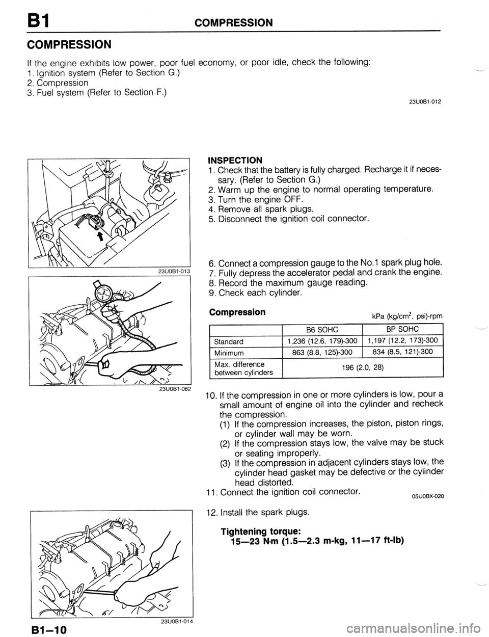
INSPECTION
1. Check that the battery is fully charged. Recharge it if neces-
sary. (Refer to Section G.)
2. Warm up the engine to normal operating temperature.
3. Turn the engine OFF.
4. Remove all spark plugs.
5. Disconnect the ignition coil connector.
6. Connect a compression gauge to the No. 1 spark plug hole.
7. Fully depress the accelerator pedal and crank the engine.
8. Record the maximum gauge reading.
9. Check each cylinder.
Compression kPa (kg/cm*, psi)-rpm
10. If the compression in one or more cylinders is low, pour a
small amount of engine oil into the cylinder and recheck
the compression.
(1) If the compression increases, the piston, piston rings,
or cylinder wall may be worn.
(2) If the compression stays low, the valve may be stuck
or seating improperly.
(3) If the compression in adjacent cylinders stays low, the
cylinder head gasket may be defective or the cylinder
head distorted.
11. Connect the ignition coil connector.
12. Install the spark plugs.
05UOBX-020
Tightening torque:
15-23 N*m (1 S-2.3 m-kg, 11-17 ft-lb)
Bl-10
Page 42 of 1164
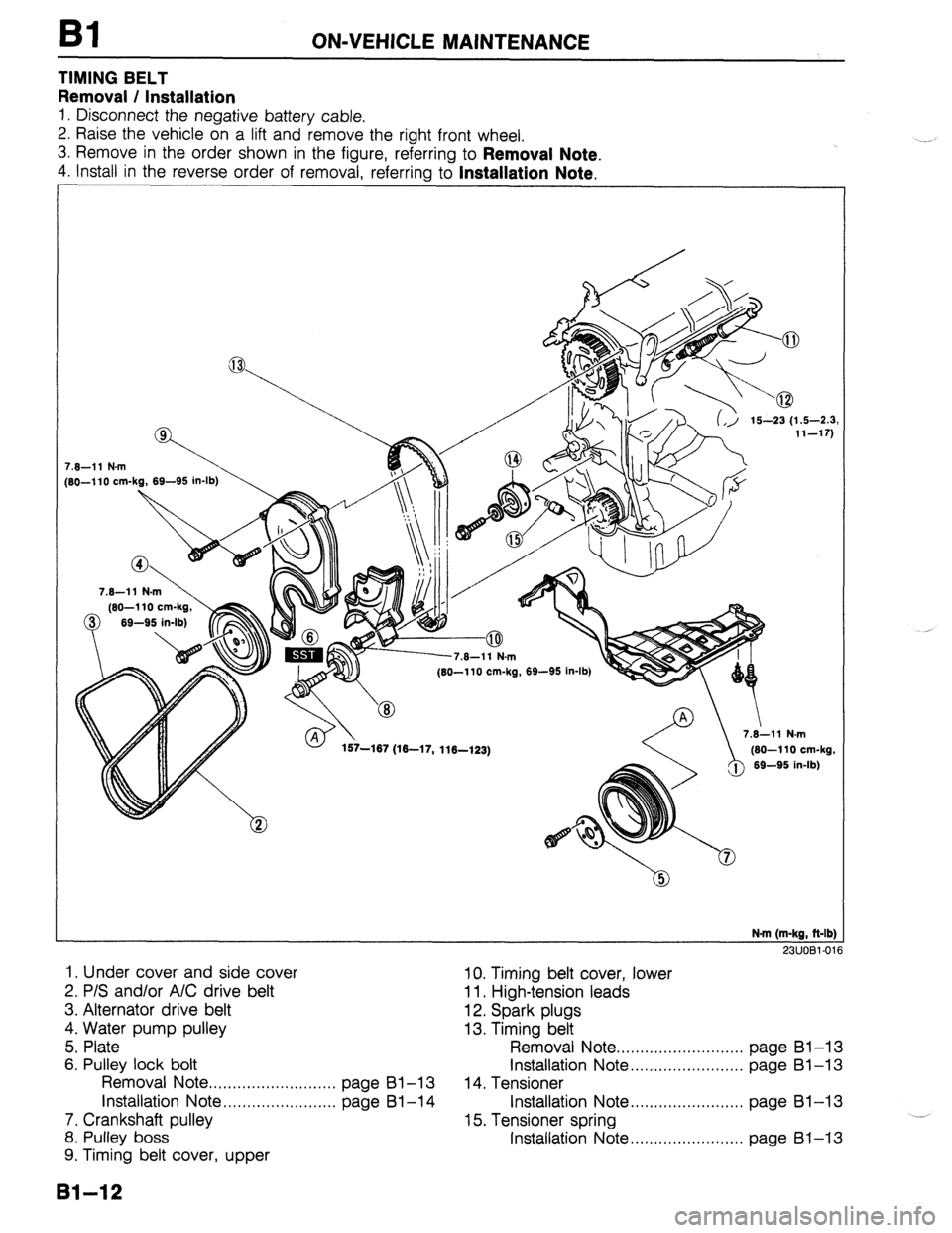
Bl ON-VEHICLE MAINTENANCE
TIMING BELT
Removal / Installation
1. Disconnect the negative battery cable.
2. Raise the vehicle on a lift and remove the right front wheel.
3. Remove in the order shown in the figure, referring to
Removal Note.
4. Install in the reverse order of removal, referrina to Installation Note.
7.6-11 N.m
[SO-110 cm-kg, 69-95 in-lb)
7.6-11 N.m
(60-l 10 cm-kg,
0 69-95 in-lb)
, .v- I . (60-110 cm-kg, 69-95 in-lb)
157-167 (16-17, 116-123) /@ 7.i11 N.m
(60-110 cm-kg,
69-95 in-lb)
N.m (m-kg, ft-lb]
23UOBl-01
1. Under cover and side cover 10. Timing belt cover, lower
2. P/S and/or A/C drive belt 11. High-tension leads
3. Alternator drive belt 12. Spark plugs
4. Water pump pulley 13. Timing belt
5. Plate Removal Note . . . . . . . . . . . . . . . . . . . . . . . . . . . page Bl-13
6. Pulley lock bolt Installation Note . . . . . . . . . . . . . . . . . . . . . . . . page Bl-13
Removal Note ..,.,,.,....,....,...,...,, page Bl-13 14. Tensioner
installation Note . . . . . . . . . . . . . . . . . . . . . . . . page Bl-14 Installation Note . . . . . . . . . . . . . . . . . . . . . . . . page 81-13
7. Crankshaft pulley 15. Tensioner spring .__
8. Pulley boss Installation Note . . . . . . . . . . . . . . . . . . . . . . . . page 61-13
9. Timing belt cover, upper
131-12
Page 45 of 1164
ON-VEHICLE MAINTENANCE Bl
Steps After Installation
1. Connect the negative battery cable.
2. Start the engine and check as follows:
l Ignition timing. (Refer to page 91-8.)
03UOBl-026
. .
81-15
Page 46 of 1164
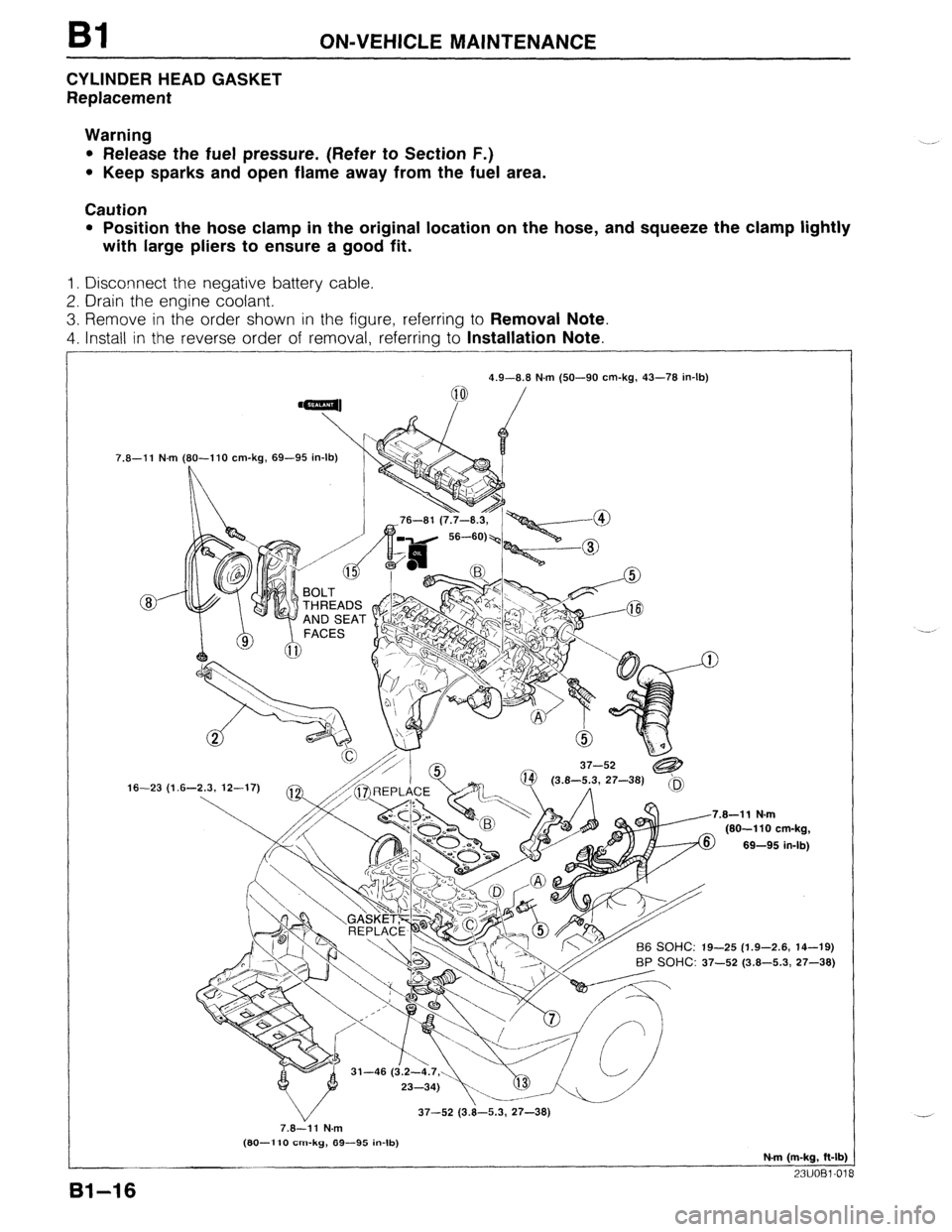
Bl ON-VEHICLE MAINTENANCE
CYLINDER HEAD GASKET
Replacement
Warning
l Release the fuel pressure. (Refer to Section F.)
l Keep sparks and open flame away from the fuel area.
Caution
l Position the hose clamp in the original location on the hose, and squeeze the clamp lightly
with large pliers to ensure a good fit.
1. Disconnect the negative battery cable.
2. Drain the engine coolant.
3. Remove in the order shown in the figure, referring to Removal Note.
4. Install in the reverse order of removal, referring to Installation Note.
7.8-11 N.m
16-23 (1 4.9-8.8 N.m (50-90 cm-kg, 43-78 in-lb)
(80-l 10 cm-kg, 69-95 in-lb)
L
.8-11 N.m
(80-110 cm-kg,
69-95 in-lb)
-25 (1.9-2.6, 14-19)
BP SOHC: 37-52 (3.8-5.3, 27-38)
37-52 (3.8-5.3, 27-38)
7.8-11 N.m
(80-l 10 cm-kg, 89-95 in-lb)
N-m (m-kg, ft-lb)
23UOBl-01
81-16
Page 49 of 1164
.
ON-VEHICLE MAINTENANCE
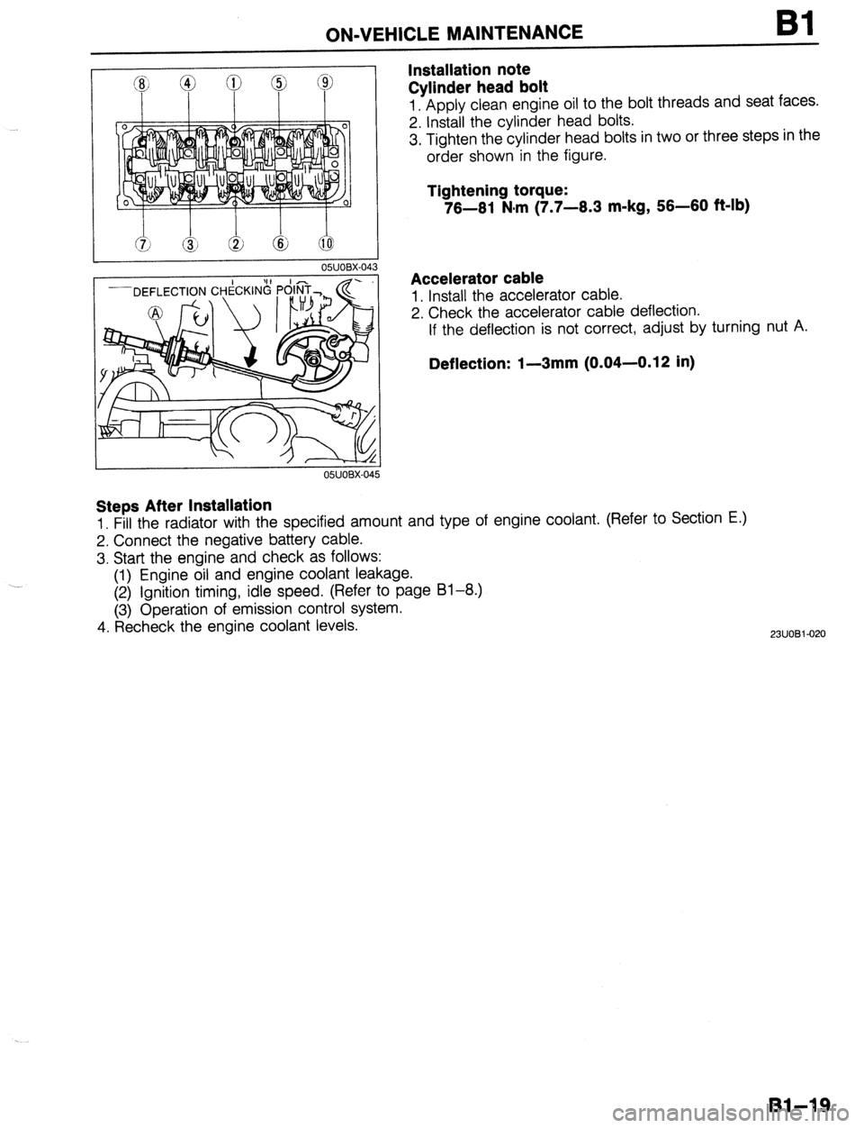
Installation note
Cylinder head bolt Bl
1. Apply clean engine oil to the bolt threads and seat faces.
2. Install the cylinder head bolts.
3. Tighten the cylinder head bolts in two or three steps in the
order shown in the figure.
Tightening torque:
76-61 N#m (7.7-6.3 m-kg, 56-60 f&lb)
Accelerator cable
1. Install the accelerator cable.
2. Check the accelerator cable deflection.
If the deflection is not correct, adjust by turning nut A.
Deflection: I-3mm (0.04-0.12 in)
Steps After Installation
1. Fill the radiator with the specified amount and type of engine coolant. (Refer to Section E.)
2. Connect the negative battery cable.
3. Start the engine and check as follows:
(1) Engine oil and engine coolant leakage.
(2) Ignition timing, idle speed. (Refer to page 81-8.)
(3) Operation of emission control system.
4. Recheck the engine coolant levels.
2311081-020
Bl-19
Page 50 of 1164
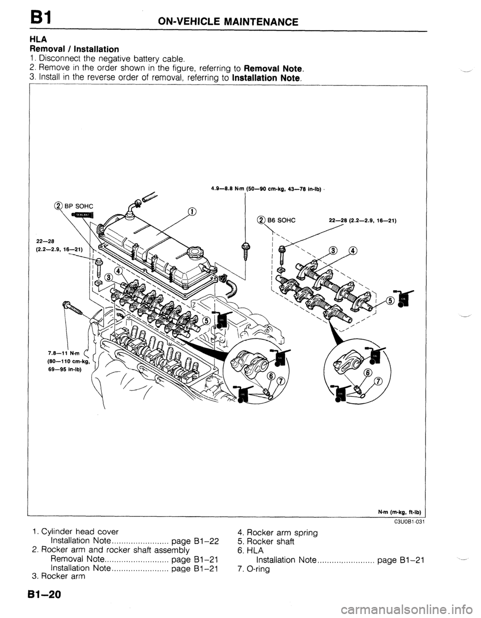
Bl ON-VEHICLE MAINTENANCE
HLA
Removal / Installation
1. Disconnect the negative battery cable.
2. Remove in the order shown in the figure, referring to
Removal Note.
3. Install in the reverse order of removal, referring to Installation Note.
-
4.9-0.8 N.I
@ BP SOHC
22-28
12.2-2.9. 16-2 m (SO-SO cm-kg, 43-78 in-lb)
N.m (m-kg, ft-lb)
03UOBl-03
1. Cylinder head cover
Installation
Note . . . . . . . . . . . . . . . . . . . . . . . . page 4. Rocker arm spring
81-22
5. Rocker shaft
2. Rocker arm and rocker shaft assembly
6. HLA
Removal Note . . . . . . . . . . . . . . . . . . . . . . . . . . .
page 81-21
Installation Note . . . . . . . . . . . . . . . . . . . . . . . . page Installation Note ,.........,............. page 81-21
---
81-21
3. Rocker arm 7. O-ring
8140
Page 52 of 1164

Bl ON-VEHICLE MAINTENANCE
8 e
93UOlA.08
EX
03UOBl-035
HEAD COVER
)
23UOBl-023
Steps After Installation
1, Connect the negative battery cable.
2. Start the engine and fully warm up.
3. Verify that there is no tappet noise. 2. Install the rocker arm and rocker shaft assembly.
Caution
l The bolts must be tightened gradually and in the or-
der shown in the figure.
Tightening torque:
22-28 N-m (2.2-2.9 m-kg, 18-21 ft-lb)
BP SOHC
1. Assemble the rocker arm and rocker shaft assembly as
shown in the figure.
Caution
l Face the rocker shaft identification mark upward.
l The installation bolt holes are different for the ex-
haust and intake sides.
Identification mark
IN . . . . . . . . . . White
EX . . . . . . . . . . . Blue
2. Install the rocker arm and rocker shaft assembly.
3. Tighten the rocker arm bolts in two or three steps in the or-
der shown in the figure.
Tightening torque:
22-28 Nsrn (2.2-2.9 m-kg, 16-21 ft-lb)
Cylinder head cover
1. Install the cylinder head cover.
Tightening torque
Bolt @:
4.9-8.8 N-m (50-90 cmikg, 43-78 in-lb)
Bolt @:
7.8-l 1 Nnrn (80-l 10 cm-kg, 69-95 in-lb)
Caution
l If the head cover gasket is reused, apply sealant in
the groove as shown.
03UOBl-038
.-
Bl-22