fuse diagram MAZDA PROTEGE 1992 Workshop Manual
[x] Cancel search | Manufacturer: MAZDA, Model Year: 1992, Model line: PROTEGE, Model: MAZDA PROTEGE 1992Pages: 1164, PDF Size: 81.9 MB
Page 857 of 1164

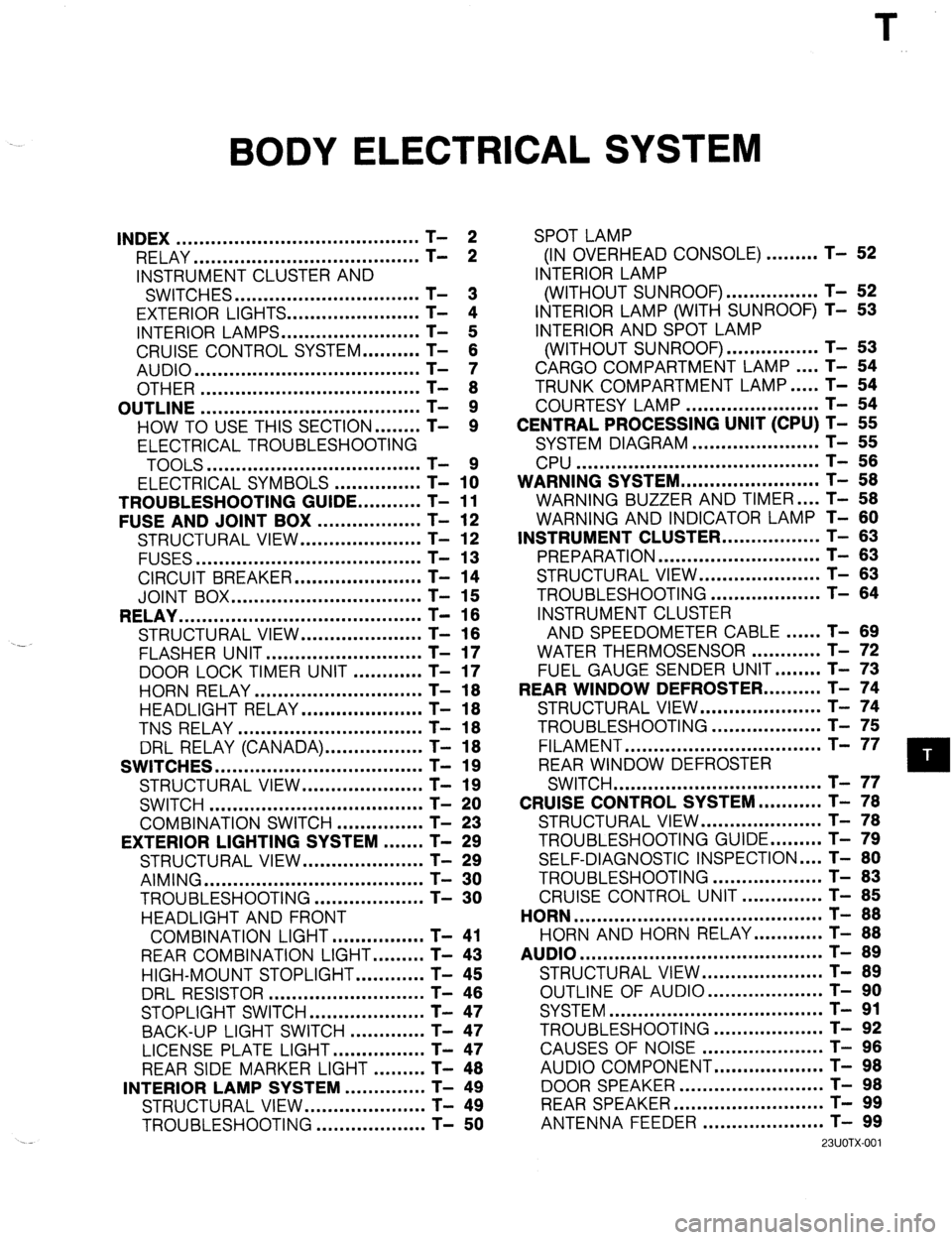
BODY ELECTRICAL SYSTEM
INDEX .......................................... T- 2
RELAY ....................................... T- 2
INSTRUMENT CLUSTER AND
SWITCHES ................................ T- 3
EXTERIOR LIGHTS.. ..................... T- 4
INTERIOR LAMPS.. ...................... T- 5
CRUISE CONTROL SYSTEM.. ........ T- 6
AUDIO ....................................... T- 7
OTHER ...................................... T- 8
OUTLINE ...................................... T- 9
HOW TO USE THIS SECTION.. ...... T- 9
ELECTRICAL TROUBLESHOOTING
TOOLS .....................................
ELECTRICAL SYMBOLS - ............... T- 1x
TROUBLESHOOTING GUIDE.. .........
T- 11
FUSE AND JOINT BOX ..................
T- 12
STRUCTURAL VIEW.. ...................
T- 12
FUSES ....................................... T- 13
CIRCUIT BREAKER.. ....................
T- 14
JOINT BOX ................................. T- 15
RELAY .......................................... T- 16
STRUCTURAL VIEW.. ...................
T- 16
.-
FLASHER UNIT ........................... T- 17
DOOR LOCK TIMER UNIT ............
T- 17
HORN RELAY ............................. T- 18
HEADLIGHT RELAY.. ................... T- 18
TNS RELAY ................................ T- 18
DRL RELAY (CANADA). ................ T- 18
SWITCHES .................................... T- 19
STRUCTURAL VIEW.. ................... T- 19
SWITCH ..................................... T- 20
COMBINATION SWITCH ...............
T- 23
EXTERIOR LIGHTING SYSTEM ....... T- 29
STRUCTURAL VIEW.. ...................
T- 29
AIMING ...................................... T- 30
TROUBLESHOOTING.. .................
T- 30
HEADLIGHT AND FRONT
COMBINATION LIGHT.. ..............
T- 41
REAR COMBINATION LIGHT.. ....... T- 43
HIGH-MOUNT STOPLIGHT.. .......... T- 45
DRL RESISTOR ........................... T- 46
STOPLIGHT SWITCH.. .................. T- 47
BACK-UP LIGHT SWITCH ............. T- 47
LICENSE PLATE LIGHT.. ..............
T- 47
REAR SIDE MARKER LIGHT ......... T- 48
INTERIOR LAMP SYSTEM ..............
T- 49
STRUCTURAL VIEW.. ...................
T- 49
TROUBLESHOOTING ...................
T- 50 SPOT LAMP
(IN OVERHEAD CONSOLE) ......... T- 52
INTERIOR LAMP
(WITHOUT SUNROOF). ............... T- 52
INTERIOR LAMP (WITH SUNROOF) T- 53
INTERIOR AND SPOT LAMP
(WITHOUT SUNROOF). ............... T- 53
CARGO COMPARTMENT LAMP.. .. T- 54
TRUNK COMPARTMENT LAMP.. ... T- 54
COURTESY LAMP ....................... T- 54
CENTRAL PROCESSING UNIT (CPU) T- 55
SYSTEM DIAGRAM ...................... T- 55
CPU .......................................... T- 56
WARNING SYSTEM.. ...................... T- 58
WARNING BUZZER AND TIMER .... T- 58
WARNING AND INDICATOR LAMP T- 60
INSTRUMENT CLUSTER.. ............... T- 63
PREPARATION ............................ T- 63
STRUCTURAL VIEW ..................... T- 63
TROUBLESHOOTING ................... T- 64
INSTRUMENT CLUSTER
AND SPEEDOMETER CABLE.. .... T- 89
WATER THERMOSENSOR ............ T- 72
FUEL GAUGE SENDER UNIT.. ...... T- 73
REAR WINDOW DEFROSTER.. ........ T- 74
STRUCTURAL VIEW.. ................... T- 74
TROUBLESHOOTING ................... T- 75
FILAMENT .................................. T- 77
REAR WINDOW DEFROSTER
SWITCH .................................... T- 77
CRUISE CONTROL SYSTEM.. ......... T- 78
STRUCTURAL VIEW.. ................... T- 78
TROUBLESHOOTING GUIDE.. ....... T- 79
SELF-DIAGNOSTIC INSPECTION .... T- 80
TROUBLESHOOTING ................... T- 83
CRUISE CONTROL UNIT .............. T- 85
HORN ........................................... T- 88
HORN AND HORN RELAY.. .......... T- 88
AUDIO .......................................... T- 89
STRUCTURAL VIEW.. ................... T- 89
OUTLINE OF AUDIO.. .................. T- 90
SYSTEM ..................................... T- 91
TROUBLESHOOTING ................... T- 92
CAUSES OF NOISE ..................... T- 96
AUDIO COMPONENT.. ................. T- 98
DOOR SPEAKER .........................
REARSPEAKER .......................... ;-
- !3;
ANTENNA FEEDER ..................... T- 99
23UOTX-001
Page 1058 of 1164

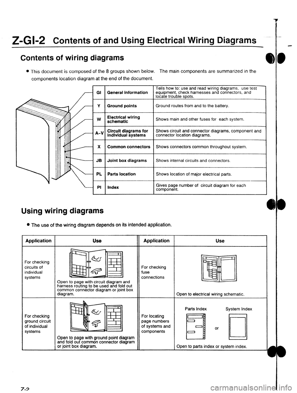
Z-Gl-2 Contents of and Using Electrical Wiring Diagrams
Contents of wiring diagrams
l This document is composed of the 8 groups shown below. The main components are summarized in the
components location diagram at the end of the document.
Tells how to: use and read wiring dragrams, use test
GI General information equipment, check harnesses and connectors, and
locate trouble spots.
Y Ground points Ground routes from and to the battery.
I
w
I Electrical wiring
schematic
I Shows main and other fuses for each system.
lndlvidual systems
I Shows circuit and connector diagrams, component and
connector location diagrams.
1
X
I Common connectors
I Shows connectors common throughout system.
I
JB Joint box diagrams Shows internal circuits and connectors.
PL Parts location Shows location of major electrical parts.
PI Index
I
I
Gives page number of circuit diagram for each
component.
Using wiring diagrams
l The use of the wiring diagram depends on its intended application. Application
For checking
circuits of
individual
systems
For checking
ground circuit
of individual
systems 7-3 Use
II Application
Open to page with circuit diagram and
harness routing to be used and fold out
common connector diagram or joint box
diagram. For checking
fuse
connections Use
Open to electrical wiring schematic.
Open to page with ground point diagram
and fold out common connector diagram
or joint box diagram. For locating
page numbers
of systems and
components Parts Index
H
Open to parts index or system index.
Page 1064 of 1164

Z-Gl-8 Reading Wiring Diagrams
Svmbols I
Symbol Meaning Symbol Meaning
Battery (I, Generates electricity through Resistance l A resistor with a constant value
chemical reaction l Mainly used to protect electrical
l Supplies direct current to circuits components in circuits by maintaining
rated voltage
l Reading resistance values
Ground (1)
l Connecting point to vehicle body or No.1 Cobr band
-A- other ground wire where current flows -No.2 Cobr band
from positive to negative terminal of -No.3 Cobr band
battery No.4 Cobr band
1
l Ground (1) indicates a ground point to Flnt color. Rerkrancs
body through wire harness
Ground (2) l Gound (2) indicates point where
component is grounded directly to body
Remark
oCurrent wilt not flow through a circuit if
ground is faulty
Fuse (1)
(box)
Fuse (2)
l Melts when current flow exceeds that
specified for circuit, stopping current
flow
Precautions
o Do not replace with fuses exceeding
specified capacity
(Cartridge)
vlain fuse/Fusible
l Electrical switching component
a Turns on when voltage is applied to Motor
0 Converts electrical energy into
mechanical energy
Transistor (2)
coiibmr (Cl
l Reading code l Pulls in and expels gases and liquids
Lamp
Number of terminals O:Low- frequency NPN
l Emits light and generates heat when
Cigarette lighter
current flows through filament a Electrical coil that generates heat
Page 1083 of 1164

“.w- MIM . FRONT- ENGINE - REAR - - __._ -._.- -.~ -~ ~.. .-_.--_* . . . . . -...-- --
- WIRING DIAGRAM
IGNITION COIL
IA-VI/ FUSE BOX FUSE BOX
Bl-02
MAIN RELAY
(FUEL INJ)
JOINT BOX
I h
(_an&=y “t Ix-16j
I- 323 HATCHBACH
h-s* A,- (WW
JB-06 DI-U3 . dl, u=nE)
I
IGNITER (GRAY) 4b
s/JB-04 B&M
FUEL TANK “NIT
JOINT
CONNECTOR
A - Bl-01
\W\“ A Bl -03 /
JO& BOX
(F)-o /x-o! (BucI() (F)-(EM) w PROTEGii
Z-27
Page 1099 of 1164

HARNESS COLOR : FRONT m ENGINE m WIRING DIAGRAM z
FUSE BOX
WATER
THERMOSWITCH
F-EM)
,:
z-43
__....._.. _ . . . . .._........ -. .._ _” .._. . . :..--..-.--, .__.
_.__.__.__.-
Page 1107 of 1164

HARNESS COLOR : FRONT- ENGINE- WIRING DIAGRAM 2
I
t
l-2J
FUSE BOX
JOINT BOX
JB-Oq
JB-04
JOINT BOX
Page 1111 of 1164

HARNESS COLOR : FRONT m ENGINE m WIRING DIAGRAM 2
I 1
E-l 1
FUSE BOX
JOINT BOX
. JB-04
-JB-O5 E-03
HEADLIGHT LH
E-01 COMBINATION
SWITCH
JOINT BOX
I
z-55
Page 1113 of 1164

LJ -2
JOINT BOX
HARNESS COLOR : FRONT- ENGINE- WIRING DIAGRAM z
4
I
FUSE BOX
JB-04
JB-05 ,
E-05
JOINT BOX
%.%‘““’
Page 1115 of 1164

HARNESS COLOR : FRONT m ENGlNE m WIRING DIAGRAM L
I
E 1-3 -I FUSE BOX
JOINT BOX
JB-06
JB-07
JOINT BOX
Page 1121 of 1164

HARNESS COLOFI : FRONT m MAR - WIRING DIAGRAM z
I I :-2
-l
HKSI MOUNT STOPLIGHT
WinH REAR SPOILER) JOINT BOX
FUSE BOX
r JOINT BOX
E-12 STOPLIGHT L”
m FUSE BOX
E-12 STOPLIGHT LH /- k?i;:7WNT STOPLIGHT
@ PROTEGC (WITH REAR S-OILW Z-65 _ _.