fuses MAZDA PROTEGE 1992 Workshop Manual
[x] Cancel search | Manufacturer: MAZDA, Model Year: 1992, Model line: PROTEGE, Model: MAZDA PROTEGE 1992Pages: 1164, PDF Size: 81.9 MB
Page 20 of 1164
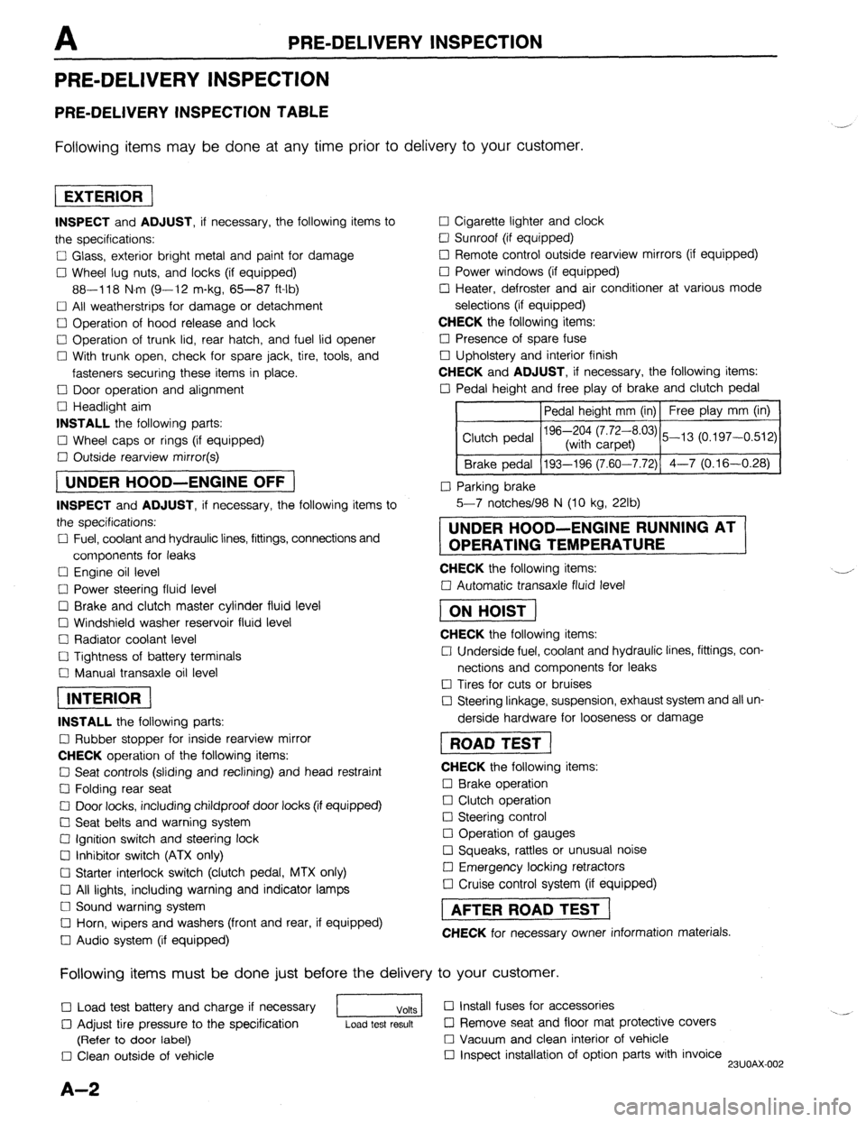
PRE-DELIVERY INSPECTION
PRE-DELIVERY INSPECTION
PRE-DELIVERY INSPECTION TABLE
Following items may be done at any time prior to delivery to your customer.
INSPECT and ADJUST, if necessary, the following items to
the specifications:
0 Glass, exterior bright metal and paint for damage
Cl Wheel lug nuts, and locks (if equipped)
88-118 N.m (9-12 m-kg, 65-87 ft-lb)
q All weatherstrips for damage or detachment
0 Operation of hood release and lock
0 Operation of trunk lid, rear hatch, and fuel lid opener
Cl With trunk open, check for spare jack, tire, tools, and
fasteners securing these items in place.
Cl Door operation and alignment
Cl Headlight aim
INSTALL the following parts:
Cl Wheel caps or rings (if equipped)
q Outside rearview mirror(s)
1 UNDER HOOD-ENGINE OFF )
INSPECT and ADJUST, if necessary, the following items to
the specifications:
0 Fuel, coolant and hydraulic lines, fittings, connections and
components for leaks
Cl Engine oil level
0 Power steering fluid level
0 Brake and clutch master cylinder fluid level
El Windshield washer reservoir fluid level
Cl Radiator coolant level
Cl Tightness of battery terminals
Cl Manual transaxle oil level
riizmiq
INSTALL the following parts:
Cl Rubber stopper for inside rearview mirror
CHECK operation of the following items:
0 Seat controls (sliding and reclining) and head restraint
Cl Folding rear seat
0 Door locks, including childproof door locks (if equipped)
Seat belts and warning system
Cl Ignition switch and steering lock
0 Inhibitor switch (ATX only)
U Starter interlock switch (clutch pedal, MTX only)
Cl All lights, including warning and indicator lamps
Cl Sound warning system
Cl Horn, wipers and washers (front and rear, if equipped)
0 Audio system (if equipped) 0 Cigarette lighter and clock
0 Sunroof (if equipped)
II Remote control outside rearview mirrors (if equipped)
Cl Power windows (if equipped)
q Heater, defroster and air conditioner at various mode
selections (if equipped)
CHECK the following items:
Cl Presence of spare fuse
0 Upholstery and interior finish
CHECK and ADJUST, if necessary, the following items:
0 Pedal height and free play of brake and clutch pedal
Pedal height mm (in) Free play mm (in)
0 Parking brake
5-7 notches/98 N (10 kg, 22lb)
UNDER HOOD-ENGINE RUNNING AT
OPERATING TEMPERATURE
CHECK the following items:
q Automatic transaxle fluid level
[I
CHECK the following items:
Cl Underside fuel, coolant and hydraulic lines, fittings, con-
nections and components for leaks
0 Tires for cuts or bruises
0 Steering linkage, suspension, exhaust system and all un-
derside hardware for looseness or damage
[I
CHECK the following items:
0 Brake operation
0 Clutch operation
Cl Steering control
Cl Operation of gauges
q Squeaks, rattles or unusual noise
Cl Emergency locking retractors
0 Cruise control system (if equipped)
1 AFTER ROAD TEST (
CHECK for necessary owner information materials.
Following items must be done just before the delivery to your customer.
q Load test battery and charge if necessary
1 Volts 1 0 Install fuses for accessories
i.. _
0 Adjust tire pressure to the specification
Load test result cl Remove seat and floor mat protective covers
(Refer to door label) 0 Vacuum and clean interior of vehicle
0 Clean outside of vehicle q Inspect installation of option parts with invoice
23UOAX-002
A-2
Page 761 of 1164

POWER DOOR LOCK SYSTEM s
Power door lock system does not operate
(All doors)
I
Check ROOM 10A and DOOR OK NG VB: Battery voltage - Repair harness and replace fuses
1
Check for battery voltage at terminal-wire (L/R) of door
lock switch connector NG
Repair harness (Fuse box-Door lock switch)
1 OK
Check terminal voltage above connector with switch
each condition
Locked
Unlocked (G/R) wire
Va
ov (G/O) wire
ov
VB
1 OK
Check door lock switch (Refer to page S-26)
Disconnect door lock timer and relay connector:
check for battery voltage at terminal-wire (W/G) NO
- Repair harness (Fuse box-Door lock timer and relay) OK
Check terminal voltage above connector with switch
each condition
Lot ked
Unlocked
VB
ov (G/O) wire
ov
VB
1 OK
NO
Repair harness =
(Door lock switch-Door lock timer and relay)
1
Check for continuity of above connector terminal-wire
(B) to ground Repair harness (Door lock timer and relay-Ground)
I OK
Connect battery voltage to terminal-wire (G) and ground
terminal-wire (R) of door lock timer and relay; check that NGT Broken harness (Door lock timer and relay-Door lock
doors lock control) or defective door lock control
Reverse above connection; check that doors unlock (Refer to inspection; page S-26)
I OK F Check door lock timer and relay (Refer to page S-26)
23uosx-007 One door lock does not operate
t
Check door lock control (Refe Replace door lock control (Refer to pages S-13, 14, 19)
I OK __ Repair harness
- (Door lock timer and relay-Door lock control)
03uosx-030
s-25
Page 841 of 1164
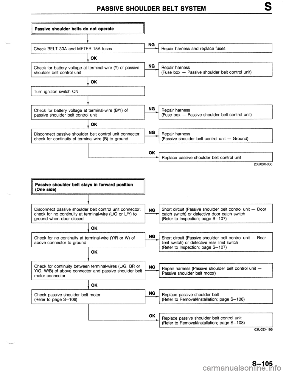
PASSIVE SHOULDER BELT SYSTEM S
II Passive shoulder belts do not operate
II
. .
Repair harness and replace fuses OK
Check for battery voltage at terminal-wire (Y) of passive E Repair harness
shoulder belt control unit (Fuse box - Passive shoulder belt control unit)
I
Turn ignition switch ON
Check for battery voltage at terminal-wire (B/Y) of
passive shoulder belt control unit OK
NG
Repair harness _
- (Fuse box - Passive shoulder belt control unit)
Disconnect passive shoulder belt control unit connector; NGz Repair harness
check for continuity of terminal-wire (B) to ground (Passive shoulder belt control unit - Ground)
Replace passive shoulder belt control unit
, 23UOSX-036 Passive shoulder belt stays in forward position
(One side)
I
Disconnect passive shoulder belt control unit connector; NG Short circuit (Passive shoulder belt control unit - Door
check for no continuity at terminal-wire (L/O or L/Y) to - - catch switch) or defective door catch switch
ground when door closed (Refer to Inspection; page S-107) OK
Check for no continuity at terminal-wire (Y/R or W) of
above connector to ground OK E Short circuit (Passive shoulder belt control unit - Rear
limit switch) or defective rear limit switch
(Refer to Inspection; page S-107)
Check for continuity between terminal-wires (L/G, BR or NG
Y/G, W/B) of above connector and passive shoulder belt Repair harness (Passive shoulder belt control unit -
motor connector Passive shoulder belt motor)
I
1 OK
Check passive shoulder belt motor
(Refer to page S-106) Replace passive shoulder belt NO
:
(Refer to Removal/Installation; page S-l 08) OK
_ Replace passive shoulder belt control unit
I (Refer to Removal/Installation; page S-l 08) L I
03uosx-195
S-l 05
Page 857 of 1164
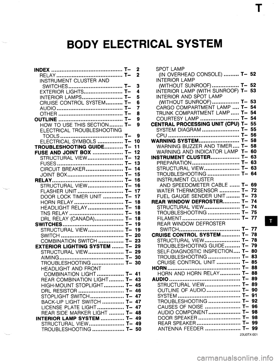
BODY ELECTRICAL SYSTEM
INDEX .......................................... T- 2
RELAY ....................................... T- 2
INSTRUMENT CLUSTER AND
SWITCHES ................................ T- 3
EXTERIOR LIGHTS.. ..................... T- 4
INTERIOR LAMPS.. ...................... T- 5
CRUISE CONTROL SYSTEM.. ........ T- 6
AUDIO ....................................... T- 7
OTHER ...................................... T- 8
OUTLINE ...................................... T- 9
HOW TO USE THIS SECTION.. ...... T- 9
ELECTRICAL TROUBLESHOOTING
TOOLS .....................................
ELECTRICAL SYMBOLS - ............... T- 1x
TROUBLESHOOTING GUIDE.. .........
T- 11
FUSE AND JOINT BOX ..................
T- 12
STRUCTURAL VIEW.. ...................
T- 12
FUSES ....................................... T- 13
CIRCUIT BREAKER.. ....................
T- 14
JOINT BOX ................................. T- 15
RELAY .......................................... T- 16
STRUCTURAL VIEW.. ...................
T- 16
.-
FLASHER UNIT ........................... T- 17
DOOR LOCK TIMER UNIT ............
T- 17
HORN RELAY ............................. T- 18
HEADLIGHT RELAY.. ................... T- 18
TNS RELAY ................................ T- 18
DRL RELAY (CANADA). ................ T- 18
SWITCHES .................................... T- 19
STRUCTURAL VIEW.. ................... T- 19
SWITCH ..................................... T- 20
COMBINATION SWITCH ...............
T- 23
EXTERIOR LIGHTING SYSTEM ....... T- 29
STRUCTURAL VIEW.. ...................
T- 29
AIMING ...................................... T- 30
TROUBLESHOOTING.. .................
T- 30
HEADLIGHT AND FRONT
COMBINATION LIGHT.. ..............
T- 41
REAR COMBINATION LIGHT.. ....... T- 43
HIGH-MOUNT STOPLIGHT.. .......... T- 45
DRL RESISTOR ........................... T- 46
STOPLIGHT SWITCH.. .................. T- 47
BACK-UP LIGHT SWITCH ............. T- 47
LICENSE PLATE LIGHT.. ..............
T- 47
REAR SIDE MARKER LIGHT ......... T- 48
INTERIOR LAMP SYSTEM ..............
T- 49
STRUCTURAL VIEW.. ...................
T- 49
TROUBLESHOOTING ...................
T- 50 SPOT LAMP
(IN OVERHEAD CONSOLE) ......... T- 52
INTERIOR LAMP
(WITHOUT SUNROOF). ............... T- 52
INTERIOR LAMP (WITH SUNROOF) T- 53
INTERIOR AND SPOT LAMP
(WITHOUT SUNROOF). ............... T- 53
CARGO COMPARTMENT LAMP.. .. T- 54
TRUNK COMPARTMENT LAMP.. ... T- 54
COURTESY LAMP ....................... T- 54
CENTRAL PROCESSING UNIT (CPU) T- 55
SYSTEM DIAGRAM ...................... T- 55
CPU .......................................... T- 56
WARNING SYSTEM.. ...................... T- 58
WARNING BUZZER AND TIMER .... T- 58
WARNING AND INDICATOR LAMP T- 60
INSTRUMENT CLUSTER.. ............... T- 63
PREPARATION ............................ T- 63
STRUCTURAL VIEW ..................... T- 63
TROUBLESHOOTING ................... T- 64
INSTRUMENT CLUSTER
AND SPEEDOMETER CABLE.. .... T- 89
WATER THERMOSENSOR ............ T- 72
FUEL GAUGE SENDER UNIT.. ...... T- 73
REAR WINDOW DEFROSTER.. ........ T- 74
STRUCTURAL VIEW.. ................... T- 74
TROUBLESHOOTING ................... T- 75
FILAMENT .................................. T- 77
REAR WINDOW DEFROSTER
SWITCH .................................... T- 77
CRUISE CONTROL SYSTEM.. ......... T- 78
STRUCTURAL VIEW.. ................... T- 78
TROUBLESHOOTING GUIDE.. ....... T- 79
SELF-DIAGNOSTIC INSPECTION .... T- 80
TROUBLESHOOTING ................... T- 83
CRUISE CONTROL UNIT .............. T- 85
HORN ........................................... T- 88
HORN AND HORN RELAY.. .......... T- 88
AUDIO .......................................... T- 89
STRUCTURAL VIEW.. ................... T- 89
OUTLINE OF AUDIO.. .................. T- 90
SYSTEM ..................................... T- 91
TROUBLESHOOTING ................... T- 92
CAUSES OF NOISE ..................... T- 96
AUDIO COMPONENT.. ................. T- 98
DOOR SPEAKER .........................
REARSPEAKER .......................... ;-
- !3;
ANTENNA FEEDER ..................... T- 99
23UOTX-001
Page 869 of 1164
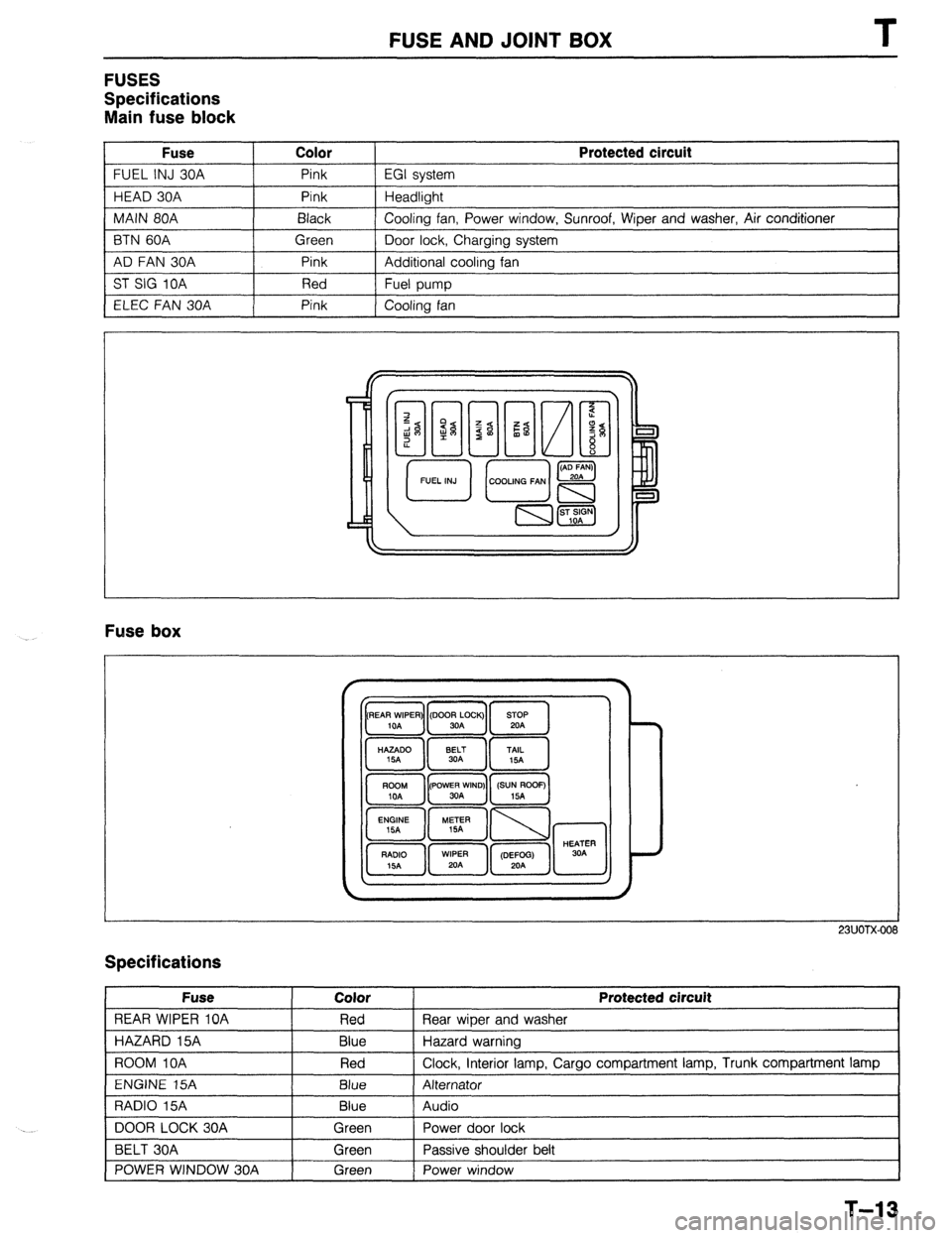
FUSE AND JOINT BOX
FUSES
Specifications
Main fuse block
Fuse Color
FUEL INJ 30A Pink
HEAD 30A Pink
MAIN 80A Black
BTN 60A Green
AD FAN 30A Pink
ST SIG 10A Red
ELEC FAN 30A Pink Protected circuit
EGI system
Headlight
Cooling fan, Power window, Sunroof, Wiper and washer, Air conditioner
Door lock, Charging system
Additional cooling fan
Fuel pump
Cooling fan
Fuse box
23UOTX-001
Specifications
Fuse
REAR WIPER 10A
HAZARD 15A
ROOM IOA
ENGINE 15A
RADIO 15A
DOOR LOCK 30A
BELT 30A
POWER WINDOW 30A Color
Red
Blue
Red
Blue
Blue
Green
Green
Green Protected circuit
Rear wiper and washer
Hazard warning
Clock, interior lamp, Cargo compartment lamp, Trunk compartment lamp
Alternator
Audio
Power door lock
Passive shoulder belt
Power window
1
T-13
Page 968 of 1164
TROUBLESHOOTING GUIDE
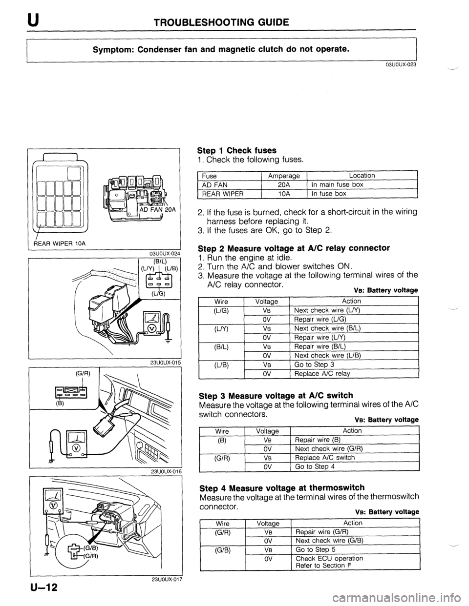
Symptom: Condenser fan and magnetic clutch do not operate.
03uoux-023
r
3EAR WIPER 10A OA
L
03uoux-02.
I
1 Step 1 Check fuses
1. Check the following fuses.
Fuse Amperage Location
AD FAN 20A In main fuse box
REAR WIPER 10A In fuse box
2. If the fuse is burned, check for a short-circuit in the wiring
harness before replacing it.
3. If the fuses are OK, go to Step 2.
I
23uoux-011
Step 2 Measure voltage at A/C relay connector
1. Run the engine at idle.
2. Turn the A/C and blower switches ON.
3. Measure the voltage at the following terminal wires of the
A/C relay connector. VEX Battery voltage
,
Wire
0-Q
W) Voltage Action
VB Next check wire (L/Y)
ov Repair wire (L/G)
V0 Next check wire (B/L)
ov
VB
ov
VB
ov Repair wire (L/Y)
Repair wire (B/L)
Next check wire (LIB)
Go to Step 3
Replace A/C relay
Step 3 Measure voltage at A/C switch
Measure the voltage at the following terminal wires of the A/C
switch connectors.
VB: Battery voltage
Step 4 Measure voltage at thermoswitch
Measure the voltage at the terminal wires of the thermoswitch
connector.
VB: Battery voltage
Wire
(G/R)
WB)
Voltage
VB
ov
VB
OV
Action
Repair wire (G/R)
Next check wire (G/B)
Go to Step 5
Check ECU ooeration
1 -. [ Refer to Secti6n F
u-12
Page 1058 of 1164
Z-Gl-2 Contents of and Using Electrical Wiring Diagrams
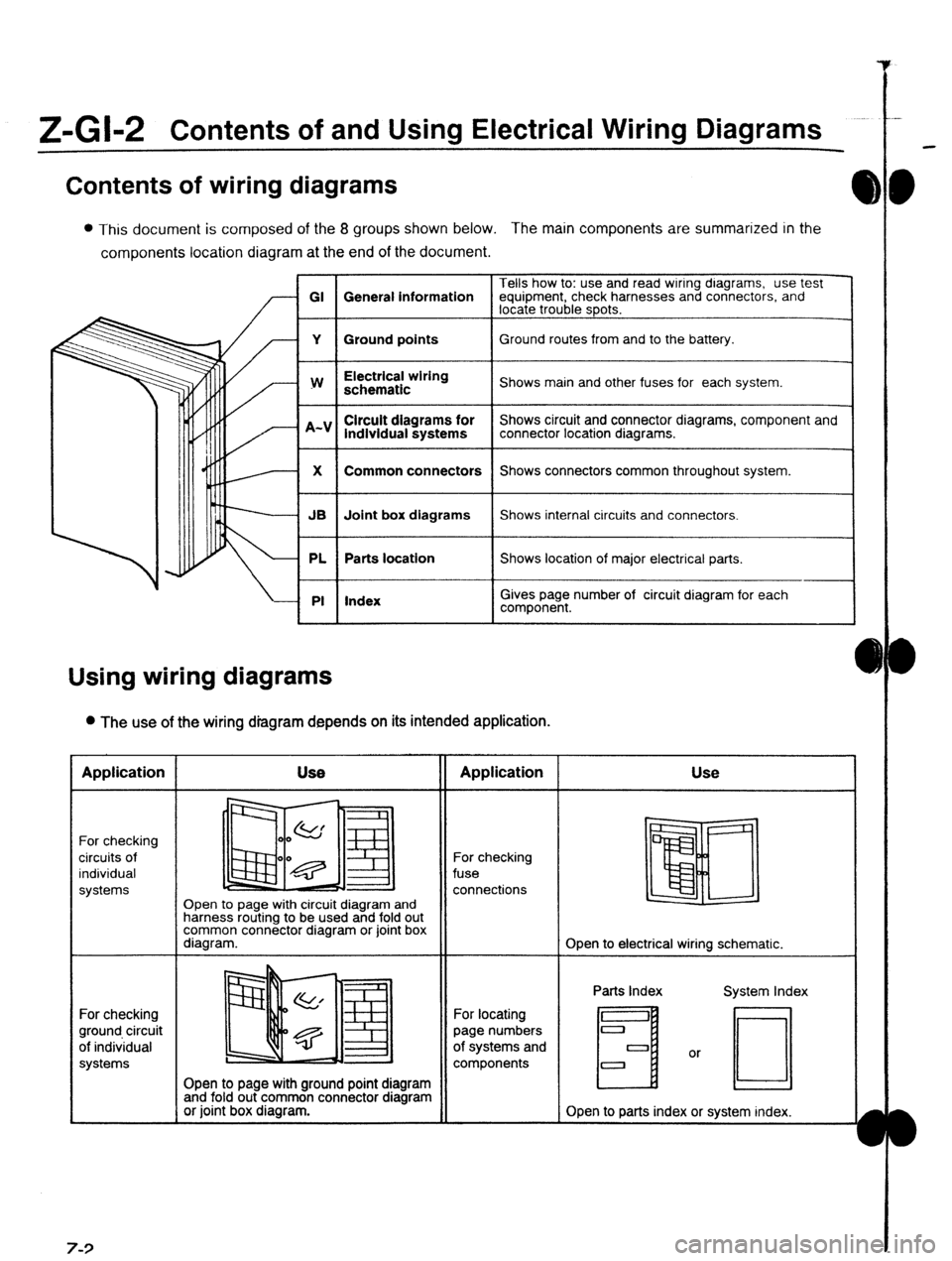
Contents of wiring diagrams
l This document is composed of the 8 groups shown below. The main components are summarized in the
components location diagram at the end of the document.
Tells how to: use and read wiring dragrams, use test
GI General information equipment, check harnesses and connectors, and
locate trouble spots.
Y Ground points Ground routes from and to the battery.
I
w
I Electrical wiring
schematic
I Shows main and other fuses for each system.
lndlvidual systems
I Shows circuit and connector diagrams, component and
connector location diagrams.
1
X
I Common connectors
I Shows connectors common throughout system.
I
JB Joint box diagrams Shows internal circuits and connectors.
PL Parts location Shows location of major electrical parts.
PI Index
I
I
Gives page number of circuit diagram for each
component.
Using wiring diagrams
l The use of the wiring diagram depends on its intended application. Application
For checking
circuits of
individual
systems
For checking
ground circuit
of individual
systems 7-3 Use
II Application
Open to page with circuit diagram and
harness routing to be used and fold out
common connector diagram or joint box
diagram. For checking
fuse
connections Use
Open to electrical wiring schematic.
Open to page with ground point diagram
and fold out common connector diagram
or joint box diagram. For locating
page numbers
of systems and
components Parts Index
H
Open to parts index or system index.
Page 1064 of 1164

Z-Gl-8 Reading Wiring Diagrams
Svmbols I
Symbol Meaning Symbol Meaning
Battery (I, Generates electricity through Resistance l A resistor with a constant value
chemical reaction l Mainly used to protect electrical
l Supplies direct current to circuits components in circuits by maintaining
rated voltage
l Reading resistance values
Ground (1)
l Connecting point to vehicle body or No.1 Cobr band
-A- other ground wire where current flows -No.2 Cobr band
from positive to negative terminal of -No.3 Cobr band
battery No.4 Cobr band
1
l Ground (1) indicates a ground point to Flnt color. Rerkrancs
body through wire harness
Ground (2) l Gound (2) indicates point where
component is grounded directly to body
Remark
oCurrent wilt not flow through a circuit if
ground is faulty
Fuse (1)
(box)
Fuse (2)
l Melts when current flow exceeds that
specified for circuit, stopping current
flow
Precautions
o Do not replace with fuses exceeding
specified capacity
(Cartridge)
vlain fuse/Fusible
l Electrical switching component
a Turns on when voltage is applied to Motor
0 Converts electrical energy into
mechanical energy
Transistor (2)
coiibmr (Cl
l Reading code l Pulls in and expels gases and liquids
Lamp
Number of terminals O:Low- frequency NPN
l Emits light and generates heat when
Cigarette lighter
current flows through filament a Electrical coil that generates heat
Page 1067 of 1164

Troubleshootina Z-GM 1
Precautions when servicing electrical system
l Note the following items when servicing the electrical system.
l Do not alter the wiring or electrical equipment in any way as this may damage the vehicle or cause a fire
due to shorting or overcapacity of a circuit.
l Always disconnect the negative (- ) battery cable first and 0 Replace blown fuses with ones having the same designated
reconnect It last when disconnecting the battery. capacity.
1OA
15A
Zaution
l Be sure that the ignition and other switches are OFF
before disconnecting or connecting the battery
terminals.
Failure to do so may damage the semi-conductor
components. Caution l Replacing a fuse with one of a larger capacity than
designated may damage components or cause an electrical
fire.
l Secure harnesses with a clamp when provided to take Up l Tape areas of the
a Be sure that the harness
any slack. harness that may rub or
is not caught or damaged
bump against sharp
when mounting
edges to protect it from
components.
damage.
Caution
l Clamp all harnesses near vibrating components(e.g.
the engine) to remove any slack and prevent Contact
due to vibration.
l Do not handle roughly or drop electrical components.
l Disconnect heat sensitive
parts (e.g. relays, ECU)
when performing
maintenance where
temperatures may exceed l Make sure that the
connectors are securely
connected when
installed.
80°C (176°F) (i.e.welding).
oid