length MAZDA PROTEGE 1992 Workshop Manual
[x] Cancel search | Manufacturer: MAZDA, Model Year: 1992, Model line: PROTEGE, Model: MAZDA PROTEGE 1992Pages: 1164, PDF Size: 81.9 MB
Page 12 of 1164
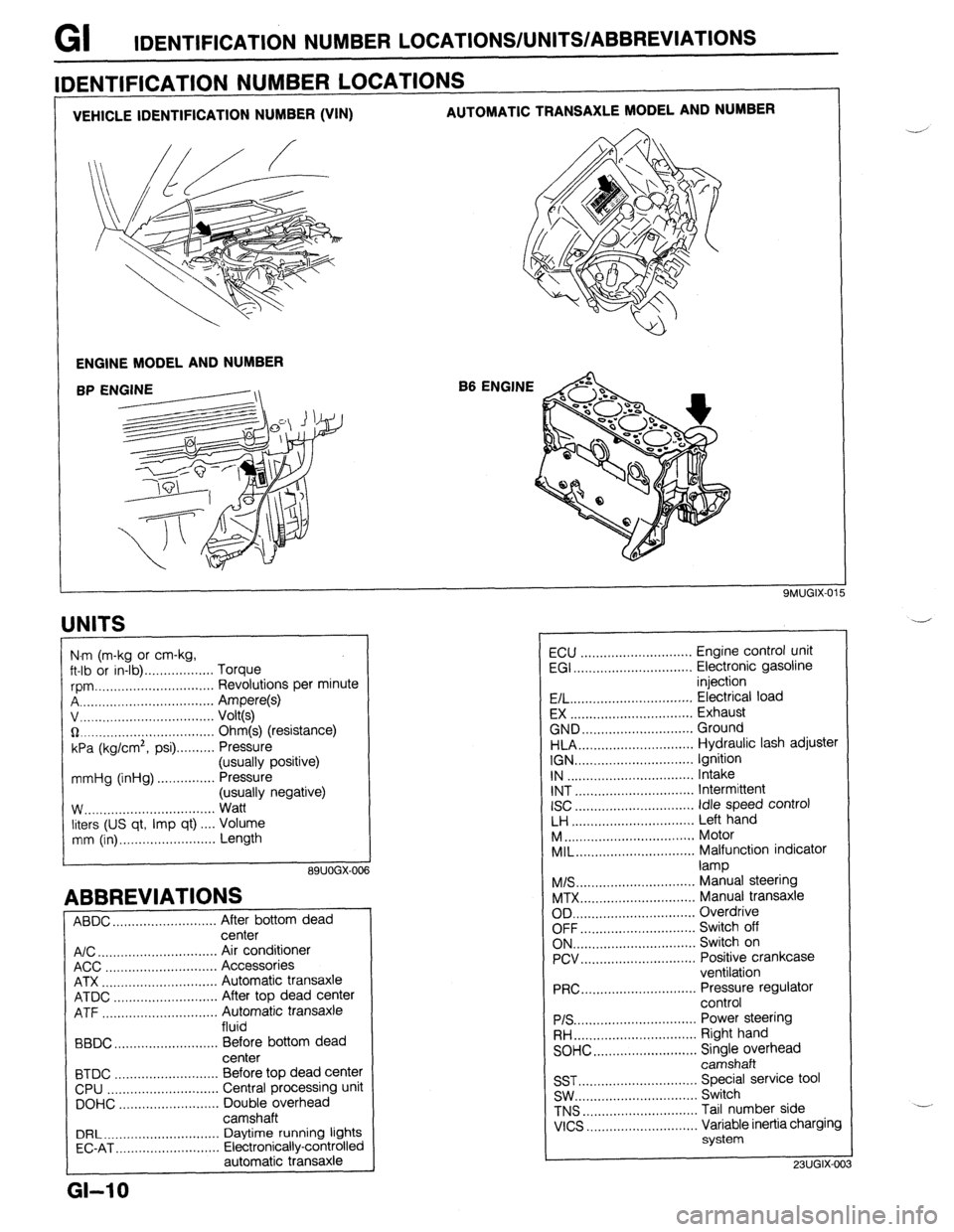
GI IDENTIFICATION NUMBER LOCATIONS/UNITS/ABBREVlATlONS
VEHICLE IDENTIFICATION NUMBER (VIN) AUTOMATIC TRANSAXLE MODEL AND NUMBER
ENGINE MODEL AND NUMBER
B6 ENGINE
IDENTIFICATION NUMBER LOCATIONS
UNITS
I
N.m (m-kg or cm-kg,
ft-lb or in-lb) . . . . . . . . . . . . . . . . . . Torque
rpm ._..,,,.............,.......... Revolutions per minute
A . . . . . . . . . . . . . . . . . Ampere(s)
v, . . . . . . . . . . . . . .
Volt(s)
$2 _....._..,......................... Ohm(s) (resistance)
kPa (kg/cm2,
psi) . . . . . . . . . . Pressure
(usually positive)
mmHg (inHg) . . . . . . . . . . . . . . . Pressure
(usually negative)
W.. . . . . . . . . . . .
Watt
liters (US qt, Imp qt) ,... Volume
mm (in) ..,......,...,........... Length
89UOGX-00
ABBREVIATIONS
ABDC . . . . . . . . . . . . . . . . . . . . .
After bottom dead
center
A/C . . . . . . . . . . . . . . . . . . . . . . . . . . . . . . .
Air conditioner
ACC ..,.,...... 3 . . . . . . . . . . . . . . . . . Accessories
ATX . . . . . . . . . . . . . . . . . . . . . . . . . . . . . . Automatic transaxle
ATDC ..,,...,...,............... After top dead center
ATF . . . . . . . . . . . . . . . . . Automatic transaxle
fluid
BBDC ,,..,.......,...,......,... Before bottom dead
center
BTDC .,......,...............,.. Before top dead center
CPU ..,,.......,...,..........,.. Central processing unit
DOHC ..,...,..,............,,.. Double overhead
camshaft
DRL ____.......................... Daytime running lights
EC-AT .,_.......,............,,.. Electronically-controlled
automatic transaxle
L
GI-10
ECU ............................. Engine control unit
EGI ............................... Electronic gasoline
injection
E/L.. .............................. Electrical load
EX ................................ Exhaust
GND.. ........................... Ground
HLA.. ............................ Hydraulic lash adjuster
IGN ............................... Ignition
IN ................................. Intake
INT ............................... Intermittent
ISC
............................... idle speed control
LH ................................ Left hand
M..
................................ Motor
MIL..
............................. Malfunction indicator
lamp
M/S..
............................. Manual steering
MTX.. ............................ Manual transaxle
OD ................................ Overdrive
OFF.. ............................ Switch off
ON.. .............................. Switch on
PCV.. ............................ Positive crankcase
ventilation
PRC..
............................ Pressure regulator
control
PIS ................................ Power steering
RH..
.............................. Right hand
SOHC.. .........................
z;;kiprhead
SST ............................... Special service tool
SW.. .............................. Switch
TNS
.............................. Tail number side
VICS
............................. Variable inertia charging
system
23UGIX-00
Page 85 of 1164
INSPECTION / REPAIR Bl
1
I
0311082-007
STEM TIP
MARGIN
THICKNESS
23UOBl-072
2311091.04:
2311091.04.
II- VALVE STEM
VALVE
CLEARANCE
J 05UOBX-125
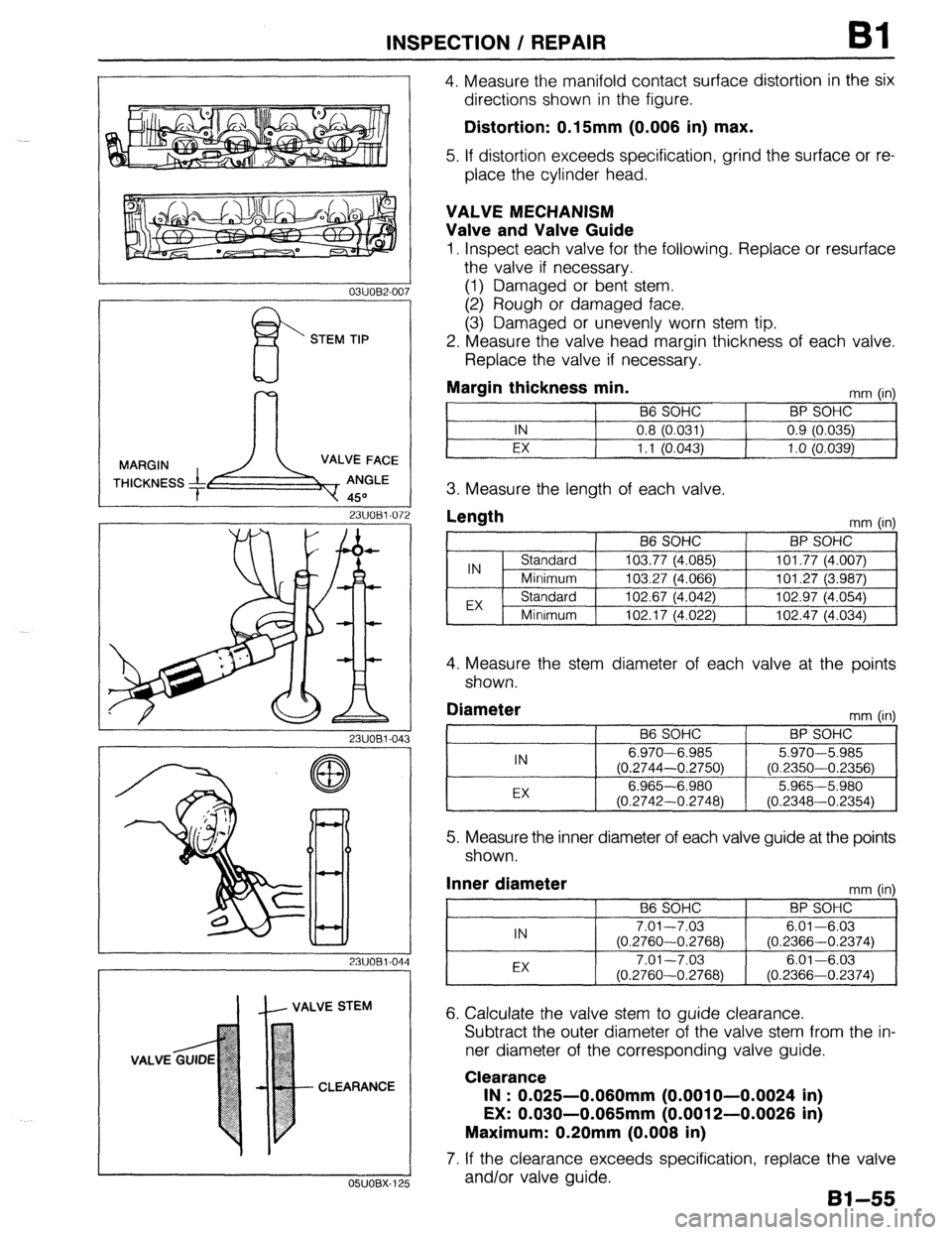
4. Measure the manifold contact surface distortion in the six
directions shown in the figure.
Distortion: 0.15mm (0.006 in) max.
5. If distortion exceeds specification, grind the surface or re-
place the cylinder head.
VALVE MECHANISM
Valve and Valve Guide
1. Inspect each valve for the following. Replace or resurface
the valve if necessary.
(1) Damaged or bent stem.
(2) Rough or damaged face.
(3) Damaged or unevenly worn stem tip.
2. Measure the valve head margin thickness of each valve.
Replace the valve if necessary.
Margin thickness min.
mm (in)
B6 SOHC BP SOHC
IN 0.8 (0.031) 0.9 (0.035)
EX 1.1 (0.043)
1 .o (0.039)
3. Measure the length of each valve.
Length
mm (in)
4. Measure the stem diameter of each valve at the points
shown.
Diameter
IN
EX B6 SOHC
6.970-6.985
(0.2744-0.2750)
6.965-6.980
(0.2742-0.2748) mm (in)
BP SOHC
5.970-5.985
(0.2350-0.2356)
5.965-5.980
(0.2348-0.2354)
5. Measure the inner diameter of each valve guide at the points
shown.
Inner diameter
mm (in)
66 SOHC BP SOHC
IN 7.01-7.03 6.01-6.03
(0.2760-0.2768) (0.2366-0.2374)
EX 7.01-7.03 6.01-6.03
(0.2760-0.2768) (0.2366-0.2374)
6. Calculate the valve stem to guide clearance.
Subtract the outer diameter of the valve stem from the in-
ner diameter of the corresponding valve guide.
Clearance
IN : 0.025-0.060mm (0.0010-0.0024 in)
EX: 0.030-0.065mm (0.0012-0.0026 in)
Maximum: 0.20mm (0.008 in)
7. If the clearance exceeds specification, replace the valve
and/or valve guide.
Bl-55
Page 87 of 1164
INSPECTION / REPAIR Bl
-- 05lJOBX-13
.- __--- 0
-_.--__I__
--
05UOBX.131
B6 SOHC
EX
IN
BP SOHC --~ -____
03uoEI-09
--__.
86 SOHC -
23UOBl-073
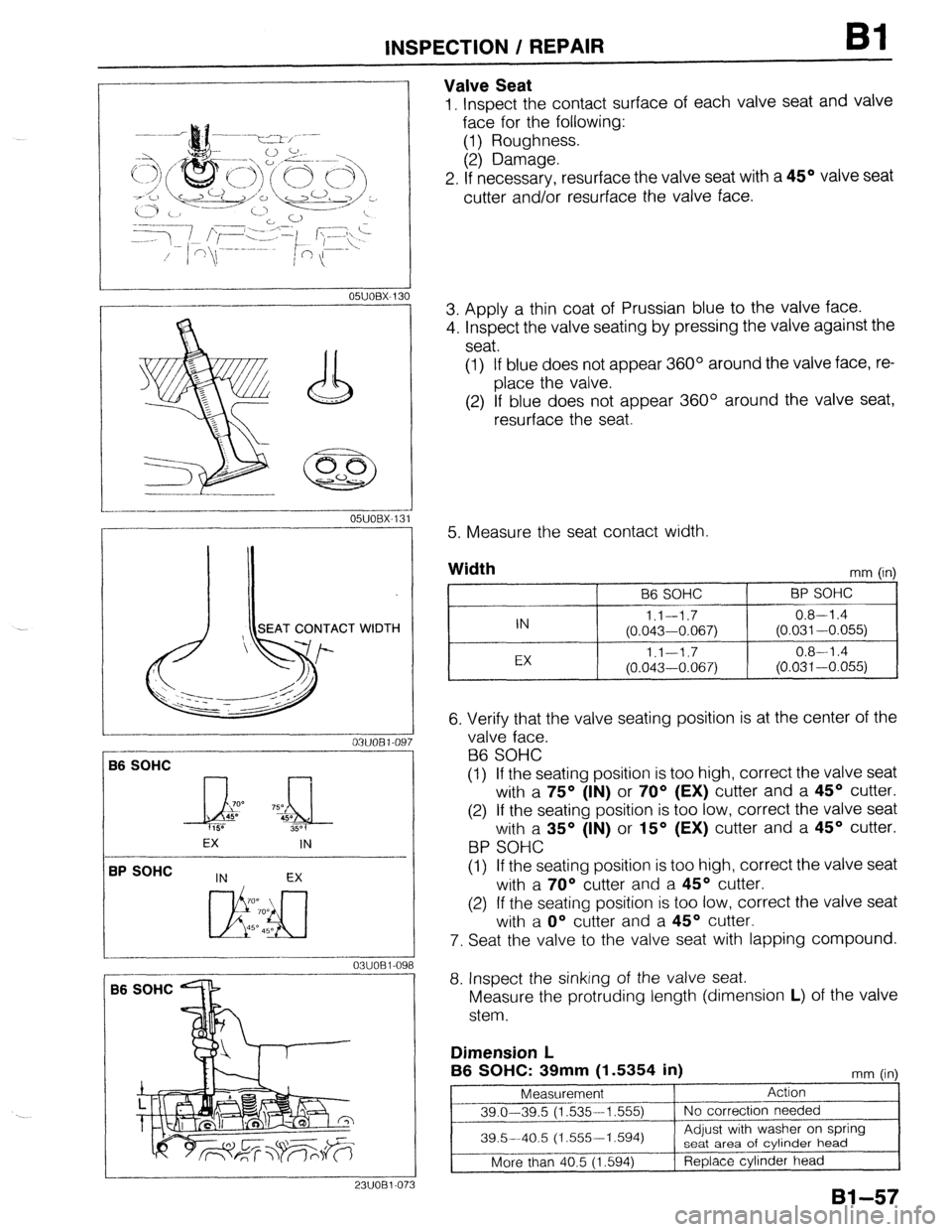
Valve Seat
1, Inspect the contact surface of each valve seat and valve
face for the following:
(1) Roughness.
(2) Damage.
2. If necessary, resurface the valve seat with a 45O valve seat
cutter and/or resurface the valve face.
3. Apply a thin coat of Prussian blue to the valve face.
4. Inspect the valve seating by pressing the valve against the
seat.
(1) If blue does not appear 360° around the valve face, re-
place the valve.
(2) If blue does not appear 360° around the valve seat,
resurface the seat
5. Measure the seat contact width.
Width
mm (in)
96 SOHC BP SOHC
IN l.l--1.7 0.8-l .4
(0.043-0.067) (0.031-0.055)
EX 1.1-1.7 0.8-l .4
(0.043-0.067) (0.031-0.055)
6. Verify that the valve seating position is at the center of the
valve face.
B6 SOHC
(1) If the seating position is too high, correct the valve seat
with a 75O (IN) or 70° (EX) cutter and a 45O cutter.
(2) If the seating position is too low, correct the valve seat
with a 35O (IN) or 15O (EX) cutter and a 45O cutter.
BP SOHC
(1) If the seating position is too high, correct the valve seat
with a 70° cutter and a 45O cutter.
(2) If the seating position is too low, correct the valve seat
with a O” cutter and a 45O cutter.
7. Seat the valve to the valve seat with lapping compound.
8. Inspect the sinking of the valve seat.
Measure the protruding length (dimension L) of the valve
stem.
Dimension L
B6 SOHC: 39mm
(1.5354 in) mm fin
Page 88 of 1164
Bl INSPECTION / REPAIR
r
BP SPHC
I /
._~~ ~_ ’
--
23UOB1-06(
1
I 2-l
_I_
23UOBl-074
lt- OUT-OF-SQUARE
BP SOHC, IN: 42.5mm (1.673 in)
EX: 41 .Omm ‘(1.614 ii)
mm (in)
Measurement Action
IN . 42.5-43.0 (1,673-l ,693) No correction needed
More than 44.0 (1.732) Replace cylinder head
EX 41 .O-41.5 (1,614-l ,634) No correction needed
More than 42.5 (1.673) Replace cylinder head
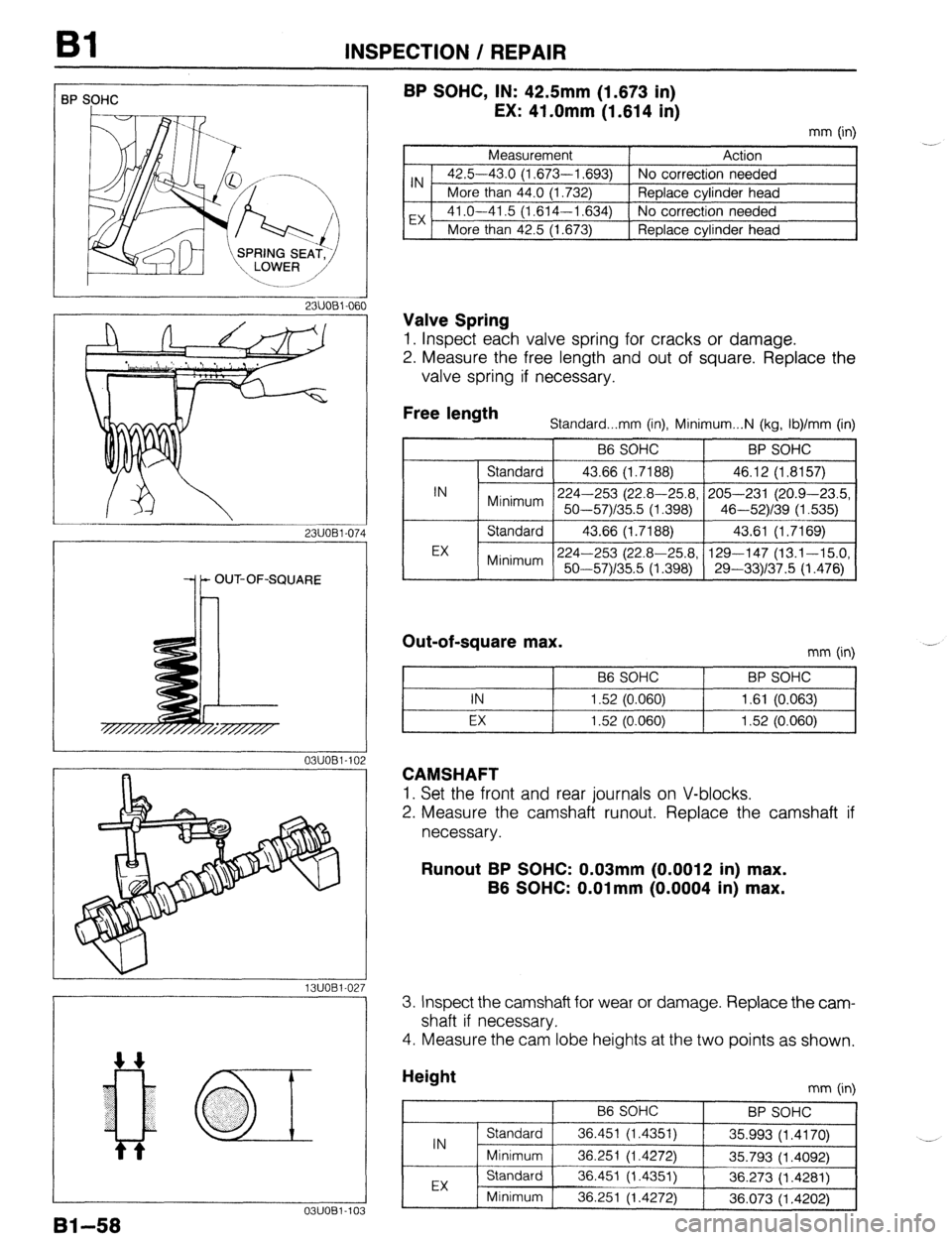
Valve Spring
1. Inspect each valve spring for cracks or damage.
2. Measure the free length and out of square. Replace the
valve spring if necessary.
Free length
Standard...mm (in), Minimum...N (kg, Ib)/mm (in)
B6 SOHC BP SOHC
I
IN Standard 43.66 (1.7188) 46.12 (1.8157)
224-253 (22.8-25.8, 205-231 (20.9-23.5,
Minimum 50-57)/35.5 (1.398) 46-52)/39 (1.535)
EX Standard 43.66 (1.7188) 43.61 (1.7169)
224-253 (22.8-25.8, 129-147 (13.1-15.0,
Minimum 50-57Y35.5 (1.398) 29-331137.5 (1.476)
Out-of-square max. mm (in)
B6 SOHC BP SOHC I
I I IN 1.52 (0.060) 1.61 (0.063)
t I I
I I EX 1.52 (0.060) 1.52 (0.060)
CAMSHAFT
1. Set the front and rear journals on V-blocks.
2. Measure the camshaft runout. Replace the camshaft if
necessary.
Runout BP SOHC: 0.03mm (0.0012 in) max.
B6 SOHC: O.Olmm (0.0004 in) max.
13UOBl.02; 3. Inspect the camshaft for wear or damage. Replace the cam-
shaft if necessary.
4. Measure the cam lobe heights at the two points as shown.
0311081-103
91-58
mm (in)
Page 95 of 1164
INSPECTION / REPAIR 81
---
L
25mm (1 .O in) min.
OSJOBX-161
DAMAGE,
WEAR
05UOBX-16!
03UOEl-12: 7
05UOBX-17: 2 05UOBX-170
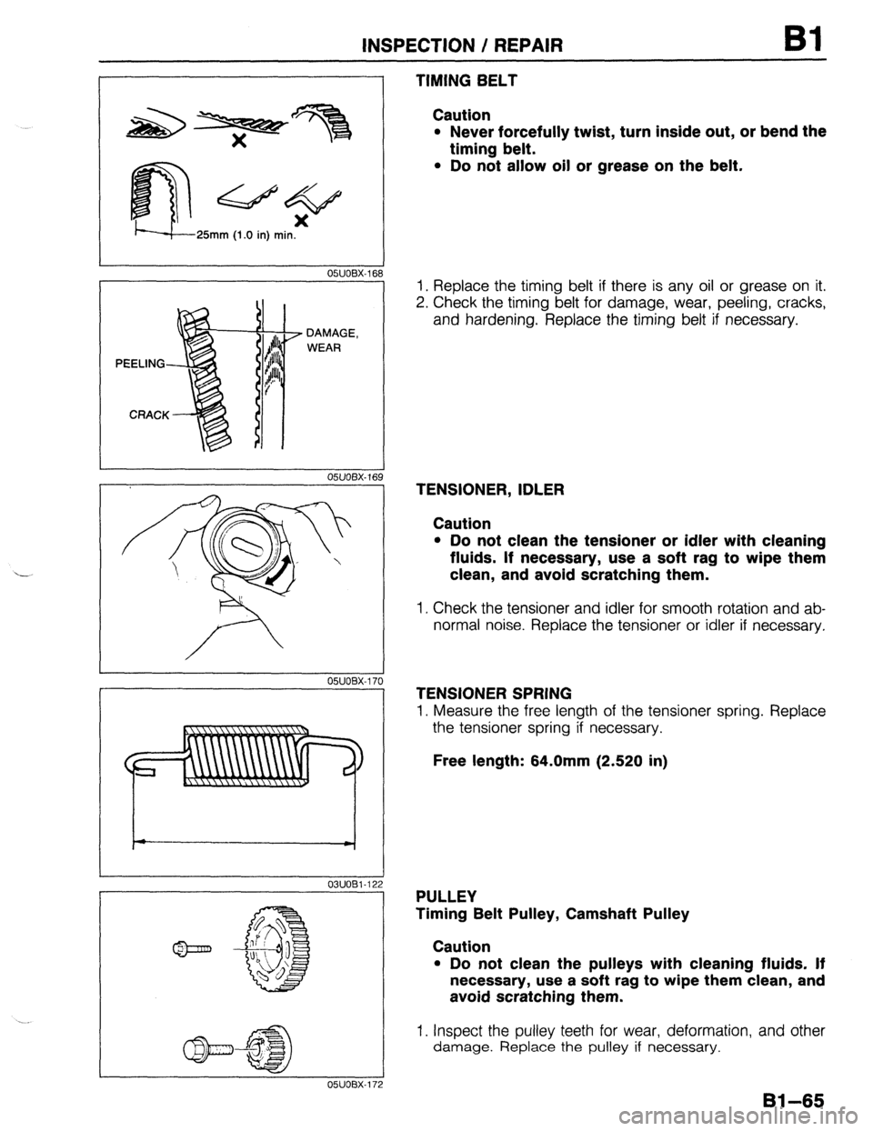
TIMING BELT
Caution
l Never forcefully twist, turn inside out, or bend the
timing belt.
l Do not allow oil or grease on the belt.
1. Replace the timing belt if there is any oil or grease on it.
2. Check the timing belt for damage, wear, peeling, cracks,
and hardening. Replace the timing belt if necessary.
TENSIONER, IDLER
Caution
l Do not clean the tensioner or idler with cleaning
fluids. If necessary, use a soft rag to wipe them
clean, and avoid scratching them.
1. Check the tensioner and idler for smooth rotation and ab-
normal noise. Replace the tensioner or idler if necessary,
TENSIONER SPRING
1. Measure the free length of the tensioner spring. Replace
the tensioner spring if necessary.
Free length: 64.0mm (2.520 in)
PULLEY
Timing Belt Pulley, Camshaft Pulley
Caution
l Do not clean the pulleys with cleaning fluids. If
necessary, use a soft rag to wipe them clean, and
avoid scratching them.
1. Inspect the pulley teeth for wear, deformation, and other damage. Replace the pulley if necessary.
Bl-65
Page 187 of 1164

INSPECTION / REPAIR B2
0311082-007
I!!?
STEM TIP
23UOBZ03f
23UOW03i
IL VALVE STEM
OWOBX-125 CLEARANCE
4. Measure the manifold contact surface distortion in the four
directions shown in the figure.
Distortion: 0.15mm (0.006 In) max.
5. If distortion exceeds specification, grind the surface or re-
place the cylinder head.
VALVE MECHANISM
Valve and Valve Guide
1. inspect each valve for the following. Replace or resurface
the valve if necessary.
(1) Damaged or bent stem.
(2) Rough or damaged face.
(3) Damaged or unevenly worn stem tip.
2. Measure the valve head margin thickness of each valve.
Replace the valve if necessary.
Margin thickness
IN : 0.9mm (0.0354 in)
EX: l.Omm (0.0394 in)
3. Measure the length of each valve.
Length
Standard
IN : 101.34mm (3.9696 in)
EX: 101.44mm (3.9937 in)
Minimum
IN : 100.64mm (3.9701 in)
EX: 100.94mm (3.9740 in)
4. Measure the stem diameter of each valve at the points
shown.
Diameter
IN : 5.970-5965mm (0.2350-0.2356 in)
EX: 5.965-5960mm (0.2346-0.2354 in)
5. Measure the inner diameter of each valve guide at the points
shown.
Inner diameter
IN : 6.01-6.03mm (0.2366-0.2374 in)
EX: 6.01-6.03mm (0.2366-0.2374 in)
6. Calculate the valve stem to guide clearance.
Subtract the outer diameter of the valve stem from the in-
ner diameter of the corresponding valve guide.
Clearance
IN : 0.025-0.060mm (0.0010-0.0024 in)
EX: 0.030-0.065mm (0.0012-0.0026 in)
Maximum: 0.20mm (0.006 in)
7. If the clearance exceeds specification, replace the valve
and/or valve guide.
B2-55
Page 190 of 1164

B2 INSPECTION / REPAIR
23UOB2-060
i$
03UOB2-08
ANGLE LIMIT
Ii
0311082.Ot
w v
05UOBX-138
03UOB2-OE
82-58
I8
9. Measure the protruding length (dimension L) of the valve
stem.
Dimension L: 45.0mm (1.7717 in)
(1) If L is 45.0-45.5mm (1.772-l .791 in), no correc-
tion needed.
(2) If L is 45.5-46.5mm (1.791-l .831 in), adjust with
washer on spring seat area of cylinder head.
(3) If L is 46.5mm (1.831 in) or more, replace cylinder
head.
Valve Spring
1. Inspect each valve spring for cracks or damage.
2. Measure the free length and out-of-square. Replace the
valve spring if necessary.
Free length
Standard: 46.26mm (1.821 in)
Minimum:
224-253 N (22.8-25.8 kg, 50-57 lb)/
395mm (1.555 in)
Out-of-square: 1.62mm (0.064 in) max.
CAMSHAFT
1. Set the front and rear journals on V-blocks.
2. Measure the camshaft runout. Replace the camshaft if
necessary.
Runout: 0.03mm (0.0012 in) max.
3. Inspect the camshaft for wear or damage. Replace the cam-
shaft if necessary.
4. Measure the cam lobe heights at the two points as shown.
Height
Standard
IN : 44.094mm (1.7360 in)
EX: 44.600mm (1.7560 in)
Minimum
IN : 43.894mm (1.7281 in)
EX: 44.400mm (1.7480 in)
Page 197 of 1164
INSPECTION / REPAIR B2
25mm (1 .O in) MIN.
05UOEX-16;
DAMAGE,
WEAR
05UOBX-16
1
s
9
OWOBX-170
O-WOBX-171 .___--__-____--
OSUOBX-172
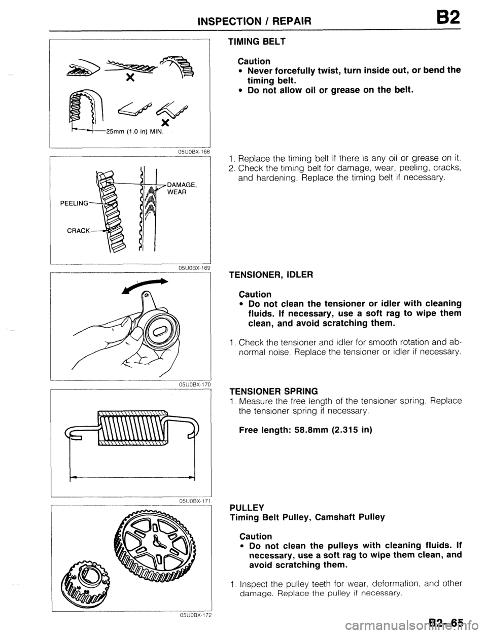
TIMING BELT
Caution
l Never forcefully twist, turn inside out, or bend the
timing belt.
l Do not allow oil or grease on the belt.
1. Replace the timing belt if there is any oil or grease on it.
2. Check the timing belt for damage, wear, peeling, cracks,
and hardening. Replace the timing belt if necessary.
TENSIONER, IDLER
Caution
l Do not clean the tensioner or idler with cleaning
fluids. If necessary, use a soft rag to wipe them
clean, and avoid scratching them.
1. Check the tensioner and idler for smooth rotation and ab-
normal noise. Replace the tensioner or idler if necessary.
TENSIONER SPRING
1. Measure the free length of the tensioner spring. Replace
the tensioner spring if necessary.
Free length: 58.8mm (2.315 in)
PULLEY
Timing Belt Pulley, Camshaft Pulley
Caution
l Do not clean the pulleys with cleaning fluids. If
necessary, use a soft rag to wipe them clean, and
avoid scratching them.
1. Inspect the pulley teeth for wear, deformation, and other
damage. Replace the pulley if necessary.
B2-65
Page 248 of 1164

OIL PUMP
OWODX-032
r----‘---I ----
L-
---- 05UODX-033
r- __I_.__^--
_- .-.. --.-.__-----^---
---7--l
L-.-.LlLd-..- ..-.---A OWODX-034
___ll_--_l___-----------
___I- 1
.i
5
INSPECTION
Pressure Spring
1 Inspect the spring for weakness or breakage.
2. Measure the free length. Replace the spring if necessary.
Free length: 45.5mm (1.791 in) -
Rotor Clearance
1. Measure the following clearances. Replace the rotor if
necessary.
Tooth tip clearance: 0.20mm (0.0079 in) max.
Outer rotor to pump body clearance:
0.22mm (0.0087 in) max.
Side clearance: 0.14mm (0.0055 in) max.
Assembly Note
Oil seal
1, Apply a small amount of clean engine oil to the lip of a new
oil seal.
2. Push the oil seal slightly in by hand,
Caution
l The oil seal must be pressed in until it is flush with
the edge of the oil pump body.
-’
3. Press the oil seal in evenly with a suitable pipe.
Oil seal outer diameter: 44mm (1.73 in)
Page 383 of 1164
![MAZDA PROTEGE 1992 Workshop Manual VARIABLE INERTIA CHARGING SYSTEM (VI-)
VARIABLE INERTIA
CHARGING SYSTEM (VICS) [DOHC]
DESCRIPTION
VACUUM CHAMBER
SHUTTER VALVE ACTUATOR
F
THREE-WAY VALVE CLOSED
5,000 rpm
SHUTTER VALVE
BELOW MAZDA PROTEGE 1992 Workshop Manual VARIABLE INERTIA CHARGING SYSTEM (VI-)
VARIABLE INERTIA
CHARGING SYSTEM (VICS) [DOHC]
DESCRIPTION
VACUUM CHAMBER
SHUTTER VALVE ACTUATOR
F
THREE-WAY VALVE CLOSED
5,000 rpm
SHUTTER VALVE
BELOW](/img/28/57077/w960_57077-382.png)
VARIABLE INERTIA CHARGING SYSTEM (VI-)
VARIABLE INERTIA
CHARGING SYSTEM (VICS) [DOHC]
DESCRIPTION
VACUUM CHAMBER
SHUTTER VALVE ACTUATOR
F
THREE-WAY VALVE CLOSED
5,000 rpm
SHUTTER VALVE
BELOW 5,000 rpm ABOVE 5,000 rpm
SHUTTER VALVE CLOSED SHUTTER VALVE OPEN
By varying the length of the intake air path in the intake manifold and dynamic chamber, the resonance
induced inertia charging effect is improved, yielding higher torque and a wider torque band.
The length of the intake track is controlled within the intake manifold and dynamic chamber by opening and
closing the shutter valve at 5,000 rpm.
l-R; FCZz consists of the shutter valves, shutter valve actuator, three-way solenoid valve, vacuum chamber,
F-117