gas type MAZDA PROTEGE 1992 Workshop Manual
[x] Cancel search | Manufacturer: MAZDA, Model Year: 1992, Model line: PROTEGE, Model: MAZDA PROTEGE 1992Pages: 1164, PDF Size: 81.9 MB
Page 33 of 1164

OUTLINE, TROUBLESHOOTING GUIDE Bl
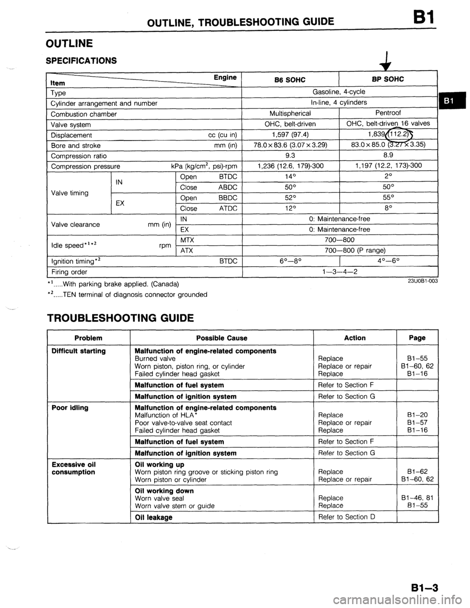
OUTLINE
SPECIFICATIONS
item Engine
Type
Cylinder arrangement and number
Combustion chamber
Valve system
Displacement cc (cu in)
Bore and stroke mm (in)
Compression ratio
Compression pressure
kPa (kg/cm2, psi)-rpm
Open BTDC
IN
Close ABDC
Valve timing
EX Open
BBDC
Close ATDC
IN
Valve clearance
mm (in)
EX
Idle speed*‘*’ MTX
rpm ATX
Ignition timing*2
BTDC
Firing order
*‘.....With parking brake applied. (Canada)
*‘.....TEN terminal of diagnosis connector grounded B6 SOHC BP SOHC
Gasoline, 4-cycle
in-line, 4 cylinders
Multispherical Pentroof
OHC, belt-driven OHC, belt-driven 16 valves
1,597 (97.4) 1,839&i 12.23
78.0 x 83.6 (3.07 x 3.29) 83.0x 85.0 -3.35)
9.3 8.9
1,236 (12.6, 179)300 1,197 (12.2, 173)-300
140 2O
50° 5o”
52O 55O
120 8
0: Maintenance-free
0: Maintenance-free
700-800
700-800 (P range)
6O----8O 4O--6O
1-3-4-2
23UOBl-003
TROUBLESHOOTING GUIDE
Problem
Difficult starting
Poor idling
Excessive oil
consumption Possible Cause
Malfunction of engine-related components
Burned valve
Worn piston, piston ring, or cylinder
Failed cvlinder head aasket Action Page
Replace 81-55
Replace or repair 81-60, 62
Reolace Bl-16
Malfunction of fuel system
1 Refer to Section F
I
Malfunction of ignition system
Malfunction of engine-related components
Malfunction of HLA*
Poor valve-to-valve seat contact
Failed cvlinder head aasket Refer to Section G
Replace
Replace or repair
Reolace 81-20
81-57
81-16
Malfunction of fuel system 1 Refer to Section F
I
Malfunction of ignition system Refer to Section G
Oil working up
Worn piston ring groove or sticking piston ring
Worn piston or cylinder
Oil working down
Worn valve seal
Worn valve stem or wide Replace
Replace or repair
Replace
Replace 81-62
Bl-60, 62
81-46, 81
81-55
Oil leakage Refer to Section D
81-3
Page 135 of 1164

OUTLINE, TROUBLESHOOTING GUIDE
OUTLINE
SPECIFICATIONS
ItC- Engine
BP DOHC
Type Gasoline, 4-cycle
Cylinder arrangement and number In-line, 4 cylinders
Combustion chamber Pentroof
Valve svstem DOHC, belt-driven 16 valves
Displacement
Bore and stroke cc (cu in) 1,839 (112.2)
mm (in) I 83.0 x 85.0 (3.27 x 3.35)
Compression ratio
Compression pressure
IN
Valve timing
EX kPa (kg/cm*, psi)-rpm
BTDC Open
Close ABDC
Open BBDC
Close ATDC 9.0
1,256 (12.8, 182)300
!zJ”
48O
56O
140
Valve clearance IN 0: Maintenance-free
mm (in)
EX 0: Marntenance-free
Idle speed *’ *’ MTX
rpm
ATX
Ignition timing*2
Firing order
::...With parking brake applied. (Canada)
. ..TEN terminal of diagnosis connector grounded BTDC 700-800
700-800 (P range)
90-l 1 O
l-3-4-2
P3UOBZ003
TROUBLESHOOTING GUIDE
Problem
Difficult starting
Poor idling
Excessive oil
consumption Possible Cause
Malfunction of engine-related components
Burned valve
Worn piston, piston ring, or cylinder
Failed cylinder head gasket
Malfunction of fuel system
Malfunction of ignition system
Malfunction of engine-related components
Malfunction of HLA*
Poor valve-to-valve seat contact
Failed cylinder head gasket
Malfunction of fuel system
Malfunction of ignition system
Oil working up
Worn piston ring groove or sticking piston ring
Worn oiston or cvlinder
Oil working down
Worn valve seal
Worn valve stem or auide
Oil leakaae i
Replace 82-55
Replace or repair 92-60, 62
Reolace B2-16
Refer to Section F
I
Replace 82-47, 79
Replace 82-55
Refer to Section 0 I
82-3
Page 241 of 1164

ENGINE OIL, OIL FILTER D
b
I
03UODX-00
ONODX-01
r
03UODX-011
ENGINE OIL
INSPECTION
1. Be sure the vehicle is on level ground.
2. Warm up the engine to normal operating temperature and
stop it.
3. Wait for five minutes.
4. Remove the oil level gauge and check the oil level and con-
dition.
5. Add or replace oil as necessary.
Note
l The distance between the L and F marks on the level
gauge represents 0.8 liter (0.85 US qt, 0.70 Imp qt).
REPLACEMENT
Warning
l Be careful when draining; the oil is hot.
1. Warm up the engine to normal operating temperature and
stop it.
2. Remove the oil filler cap and the oil pan drain plug.
3. Drain the oil into a suitable container.
4. Install a new gasket and the drain plug.
Tightening torque:
29-41 N,m (3.0-4.2 m-kg, 22-30 ft-lb)
5. Refill the engine with the specified type and amount of en-
gine oil.
6. Refit the oil filler cap.
7. Run the engine and check for leaks.
8. Check the oil level and add oil if necessary.
Oil pan capacity
B6 SOHC
BP SOHC and DOHC
liters (US qt, Imp qt)
3.0 (3.2, 2.6)
3.6G.843.2)
w
03UODX-011
D-7
Page 246 of 1164

OIL PAN
I 03UODX.02
05UOBX.20
1
05UODX-021
56 SOHC
03UODX-02
3P s
03UODX-02!
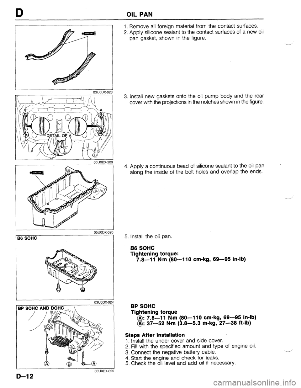
1. Remove all foreign material from the contact surfaces.
2. Apply silicone sealant to the contact surfaces of a new oil
pan gasket, shown in the figure.
3. Install new gaskets onto the oil pump body and the rear
cover with the projections in the notches shown in the figure.
4. Apply a continuous bead of silicone sealant to the oil pan
along the inside of the bolt holes and overlap the ends.
5. Install the oil pan.
B6 SOHC
Tightening torque:
7.6-11 N-m (80-110 cm-kg, 69-95 in-lb)
BP SOHC
Tightening torque
A : 7.8-l 1 N-m (80-l 10 cm-kg, 69-95 in-lb)
8 B : 37-52 N.m (3.8-5.3 m-kg, 27-38 ft-lb)
Steps After Installation
1. Install the under cover and side cover.
2. Fill with the specified amount and type of engine oil.
3. Connect the negative battery cable.
4. Start the engine and check for leaks.
5. Check the oil level and add oil if necessary.
D-12
Page 257 of 1164

RADIATOR, THERMOSTAT t
THERMOSTAT
REMOVAL / INSTALLATION INSPECTION
Check for the following and repair or replace as necessary.
1. Cracks, damage, and water leakage.
2. Bent fins (repair with a screwdriver).
3. Distorted or bent radiator inlet.
Steps After Installation
1. Fill the radiator with the specified amount and type of en-
gine coolant. (Refer to page E-6.)
2. Connect the negative battery cable.
3. Start the engine and check for leaks.
Caution
l Position the hose clamp in the original location on the hose, and squeeze the clamp lightly
with large pliers to ensure a good fit.
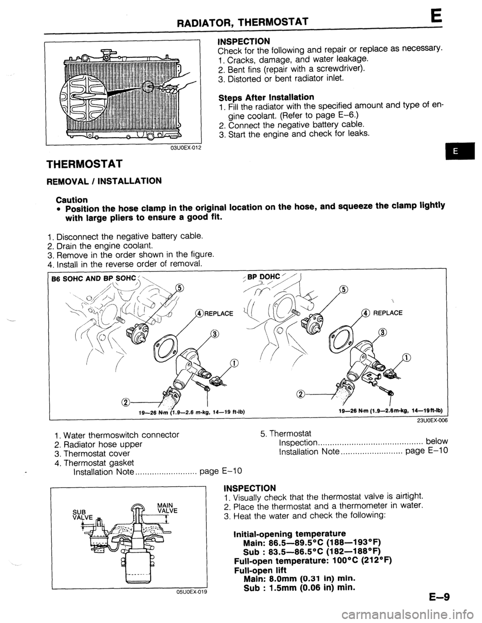
1. Disconnect the negative battery cable.
2. Drain the engine coolant.
3. Remove in the order shown in the figure.
4. Install in the reverse order of removal.
SOHC AND BP SOHC : \,
19-26 N&6.9-2.6 m-kg, 14-19 ft-lb) 19-26 N-m (l.S--2&m-kg, 14-Wft-lb)
23UOEX-006
1. Water thermoswitch connector
2. Radiator hose upper
3. Thermostat cover
4. Thermostat gasket 5. Thermostat
Inspection . . . . .., .., ,.. ,.. . . . ,.. . . . . . . . . . . . . . . . . . . . . . . below
Installation Note ..,....................... page E-10
Installation Note . . . . . . . . . . . . . . . . . . . . . . . . . .
page E-10
INSPECTION
1. Visually check that the thermostat valve is airtight.
2. Place the thermostat and a thermometer in water.
3. Heat the water and check the following:
Initial-opening temperature
Main: 86.5-89.5°C (188-193OF)
Sub : 83.5-86.5OC (182-188OF)
Full-open temperature: 1 OOOC (212OF)
Full-open lift
OSUOEX-019
Main: 8.0mm (0.31 In) min.
Sub : 1.5mm (0.06 in) min.
E-9
Page 258 of 1164

E THERMOSTAT
Installation Note JIGGLE PIN Thermostat
6 8 8
1. Install the thermostat into the cylinder head with the jiggle
pin at the top. ..__
Thermostat gasket
1. Install a new gasket with the seal print side facing the cylin-
der head.
03UOEX-014
Steps After Installation
1. Fill the radiator with the specified amount and type of engine coolant. (Refer to page E-6.)
2. Connect the negative battery cable,
3. Start the engine and check for leaks.
03UOEX-015
.-
E-IO
Page 260 of 1164

BP DOHC
L 7.8-11 N-m (60-110 cm-kg, 69-95 in-lb)
E WATER PUMP
157-167
I
(W-17, 116-123) I
I
/
I
I
I
---N-w------
---------------
----_---_
-I
N.m (m-kg, ft-lb) 1
^^, *--., ^^^
1. Timing belt
Service . . . . . . . . . . . . . . . . . . . . . . . . . . . . . . . . . . . . . . . . Section 5. Water pump assembly
B2
2. Water inlet pipe and gasket Inspect for cracks, damaged mounting
3. Water bypass pipe and O-ring surface, bearing condition, and leakage
4. Oil dip stick pipe bracket 6. Water pump gasket
Steps After Installation
1. Fill the radiator with the specified amount and type of engine coolant. (Refer to page E-6.)
2. Connect the negative battery cable,
3. Start the engine and check for leaks.
03UOEX-018
E-12
Page 1019 of 1164

TECHNICAL DATA TD
r-
RP sm.lc: I Item
Crankpin bearing Engine
86 SOHC
I -. VW.._
Crankpin bearing oil clearance mm (in) Standard 0.028-0.068 (0.001 l-0.0027)
Maximum 0.10 (0.004)
Available undersized bearing mm (in)
0.25 (O.OlO), 0.50 (0.020) 0.75 (0.030) Thrust bearing
Crankshaft end play mm (in) Standard 0.080-0.282 (0.0031-0.0111)
Maximum 0.30 (0.012)
Standard size 2.500-2.550 (0.0984-0.1004)
Bearing width mm (in) 0.25 (0.010) oversize 2.625-2.675 (0.1033-0.1053)
0.50 (0.020) oversize 2.750-2.800 (0.1083-0.1102)
0.75 (0.030) oversize 2.875-2.925 (0.1132-0.1152)
1 Timing belt
Belt deflection mm (in)/98 N (10 kg, 22 lb) 1 11 .o-13.0 (0.43-0.51) 82.
ENGINE (BP DOHC) Item
Type
Cylinder arrangement and number BP DOHC
Gasoline, 4-cycle
In-line 4-cylinders
-. I
Combustion chamber
Valve svstem DOHC, belt-d
Bore x Stroke
Total piston displacement ventroot
riven
(3.2:
mm (in) 1 83.0 x 85.0
cc (cu in) ]
7x3.35)1 1,839 (112.2)
I 16 valves I 9.0
-300
mn Compression ratio
Standard 1,256 (12.8, 182)
Compression pressure Minimum 883 (9.0, 128)-Z kPa (kglcm2,
Psi)-rPm
Maximum dif
‘ference
between eat -, h cvlinder 196 (2.0, 28)
IN Open BTDC 5O
Valve timing Close ABDC 48’
EX Open BBDC 56O
Close ATDC .4 In
IY-
IN
mm (in) EX 0 Maintenance-l
Valve clearance
0 Maintenance-i ‘ree
‘me Cylinder head
Height mm (in)
Distortion mm (in)
Grinding mm (in)
Standard
Cylinder head-to-HLA clearance mm (in) Maximum Valve and valve guide 133.8-134.0 (5.268-5.276)
0.10 (0.004) max.
0.10 (0.004) max.
0.025-0.066 (0.0010-0.0026)
0.18 (0.0071)
Valve head diameter IN
mm (in) EX 32.9-33,l (1.295-l ,303)
27.85-28.15 (1.096-1.108)
Valve head margin thickness IN
mm On) Fx 0.9 (0.0354)
1 .o fO.0393)
1 Valve face angle . .
I
FX I I
Valve length IN
Standard 101.34 (3.9898)
mm (in) Minimum 100.84 (3.9701)
Standard 101.44 (3.9937) I -, .
I
Valve stem diameter EX
Minimum loo.94 i3.974oj
IN
mm (in) - EX 5.970-5.985 (0.2350-0.2356)
5.965-5.980 (0.2348-0.2354)
mm (in) I
. , , 6.01-6.03 (0.23 166-0.2374)
1 IN
I 0.025-0.060 (0.0010-0.0024)
3.0012-0.0026)
( Maximum 0.20 (0.008)
I
TD-5
Page 1064 of 1164

Z-Gl-8 Reading Wiring Diagrams
Svmbols I
Symbol Meaning Symbol Meaning
Battery (I, Generates electricity through Resistance l A resistor with a constant value
chemical reaction l Mainly used to protect electrical
l Supplies direct current to circuits components in circuits by maintaining
rated voltage
l Reading resistance values
Ground (1)
l Connecting point to vehicle body or No.1 Cobr band
-A- other ground wire where current flows -No.2 Cobr band
from positive to negative terminal of -No.3 Cobr band
battery No.4 Cobr band
1
l Ground (1) indicates a ground point to Flnt color. Rerkrancs
body through wire harness
Ground (2) l Gound (2) indicates point where
component is grounded directly to body
Remark
oCurrent wilt not flow through a circuit if
ground is faulty
Fuse (1)
(box)
Fuse (2)
l Melts when current flow exceeds that
specified for circuit, stopping current
flow
Precautions
o Do not replace with fuses exceeding
specified capacity
(Cartridge)
vlain fuse/Fusible
l Electrical switching component
a Turns on when voltage is applied to Motor
0 Converts electrical energy into
mechanical energy
Transistor (2)
coiibmr (Cl
l Reading code l Pulls in and expels gases and liquids
Lamp
Number of terminals O:Low- frequency NPN
l Emits light and generates heat when
Cigarette lighter
current flows through filament a Electrical coil that generates heat