torque MAZDA PROTEGE 1992 Workshop Manual
[x] Cancel search | Manufacturer: MAZDA, Model Year: 1992, Model line: PROTEGE, Model: MAZDA PROTEGE 1992Pages: 1164, PDF Size: 81.9 MB
Page 5 of 1164
HOW TO USE THIS MANUAL GI
HOW TO USE THIS MANUAL
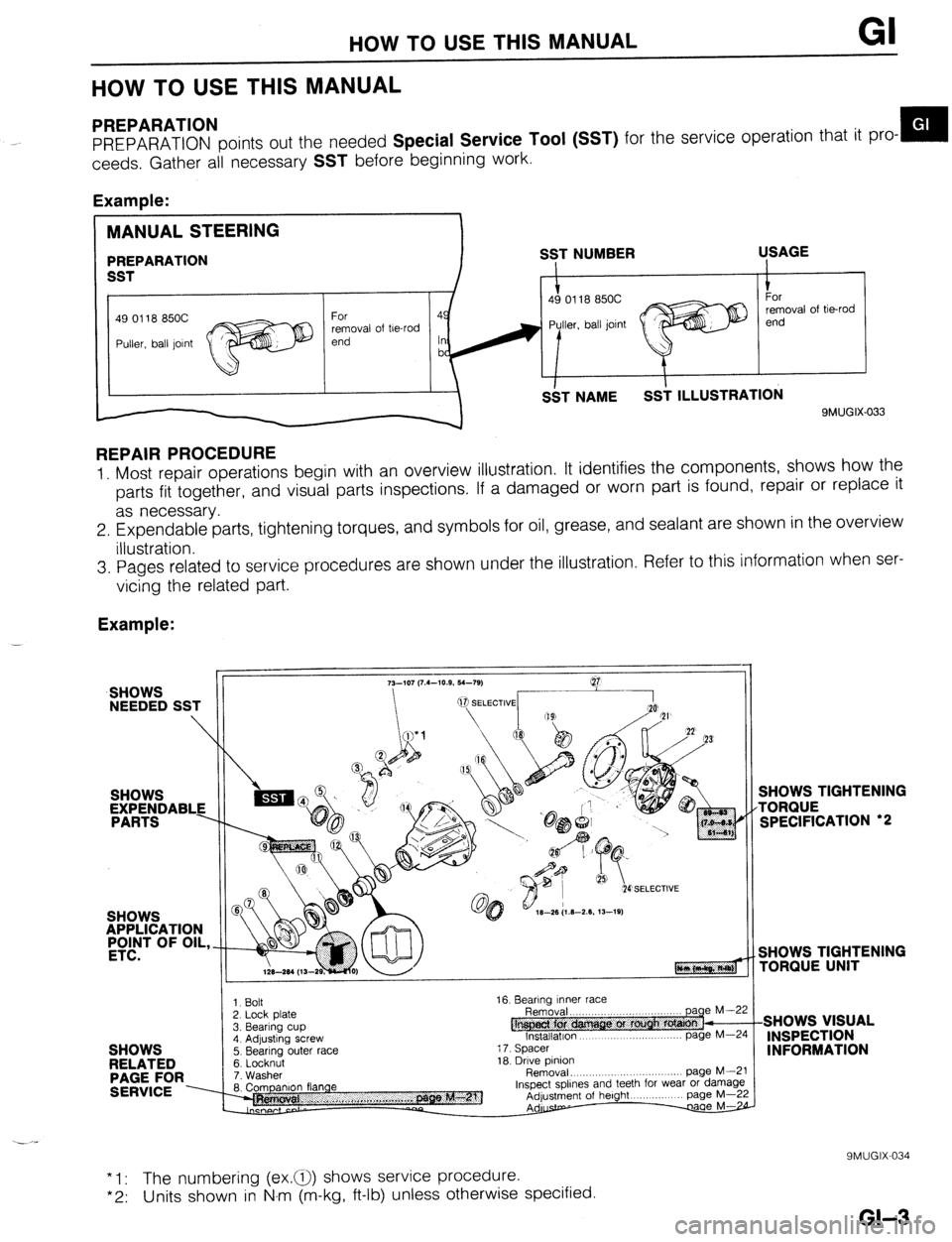
PREPARATION
PREPARATION points out the needed Special Service Tool (SST) for the service operation that it pro- m
ceeds. Gather all necessary
SST before beginning work.
Example:
49 0118 850C
removal of be-rod
9MUGIX-033
REPAIR PROCEDURE
1. Most repair operations begin with an overview illustration. It identifies the components, shows how the
parts fit together, and visual parts inspections. If a damaged or worn part is found, repair or replace it
as necessary.
2. Expendable parts, tightening torques, and symbols for oil, grease, and sealant are shown in the overview
illustration.
3. Pages related to service procedures are shown under the illustration. Refer to this information when ser-
vicing the related part.
Example:
SHOWS
NEEDED SST
SHOWS
APPLICATION
#T OF OIL,
SHOWS
RELATED
PAGE FOR
SERVICE ----
3. Bearing cup 1. Bolt
2. Lock Dlate
4. Adjusting screw
5. Bearing outer race
6. Locknut
7. Washer
8. Companion flange 16. Bearing Inner race
@ Removal. ,,,..,,,..
lnstallatlon page
page M--5 M-Z
i 7. Spacer
18. Drive pinion
Removal, .,,, ,.,, .,......... page M--i
Inspect spllnes and teeth for wear or damagl
Adjustment of height page M-2
Adurstp- w
SHOWS TIGHTENING
TORQUE
SPECIFICATION ‘2
SHOWS TIGHTENING
rORQlJE UNIT
SHOWS VISUAL
INSPECTION
INFORMATION
* 1: The numbering (ex.a) shows service procedure.
*2: Units shown in N.m (m-kg, ft-lb) unless otherwise specified.
9MUGIX-034
GI-3
Page 8 of 1164
GI FUNDAMENTAL PROCEDURES
9MUGIX-04t 3
9MUGIX-041
9MUGIX.004
I
Depending on location:
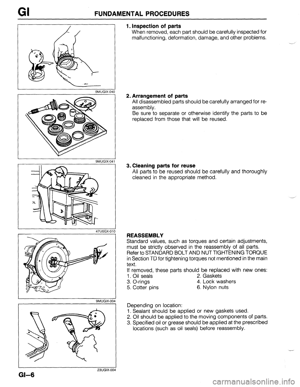
1. Inspection of parts
When removed, each part should be carefully inspected for
malfunctioning, deformation, damage, and other problems.
2. Arrangement of parts
All disassembled parts should be carefully arranged for re-
assembly.
Be sure to separate or otherwise identify the parts to be
replaced from those that will be reused.
3. Cleaning parts for reuse
All parts to be reused should be carefully and thoroughly
cleaned in the appropriate method.
REASSEMBLY
Standard values, such as torques and certain adjustments,
must be strictly observed in the reassembly of all parts.
Refer to STANDARD BOLT AND NUT TIGHTENING TORQUE
in Section TD for tightening torques not mentioned in the main
text.
If removed, these parts should be replaced with new ones:
1. Oil seals 2. Gaskets
3. O-rings 4. Lock washers
5. Cotter pins 6. Nylon nuts
1. Sealant should be applied or new gaskets used.
2. Oil should be applied to the moving components of parts.
3. Specified oil or grease should be applied at the prescribed
locations (such as oil seals) before reassembly.
I
23lJGIX.004
GI-6
Page 12 of 1164
GI IDENTIFICATION NUMBER LOCATIONS/UNITS/ABBREVlATlONS
VEHICLE IDENTIFICATION NUMBER (VIN) AUTOMATIC TRANSAXLE MODEL AND NUMBER
ENGINE MODEL AND NUMBER
B6 ENGINE
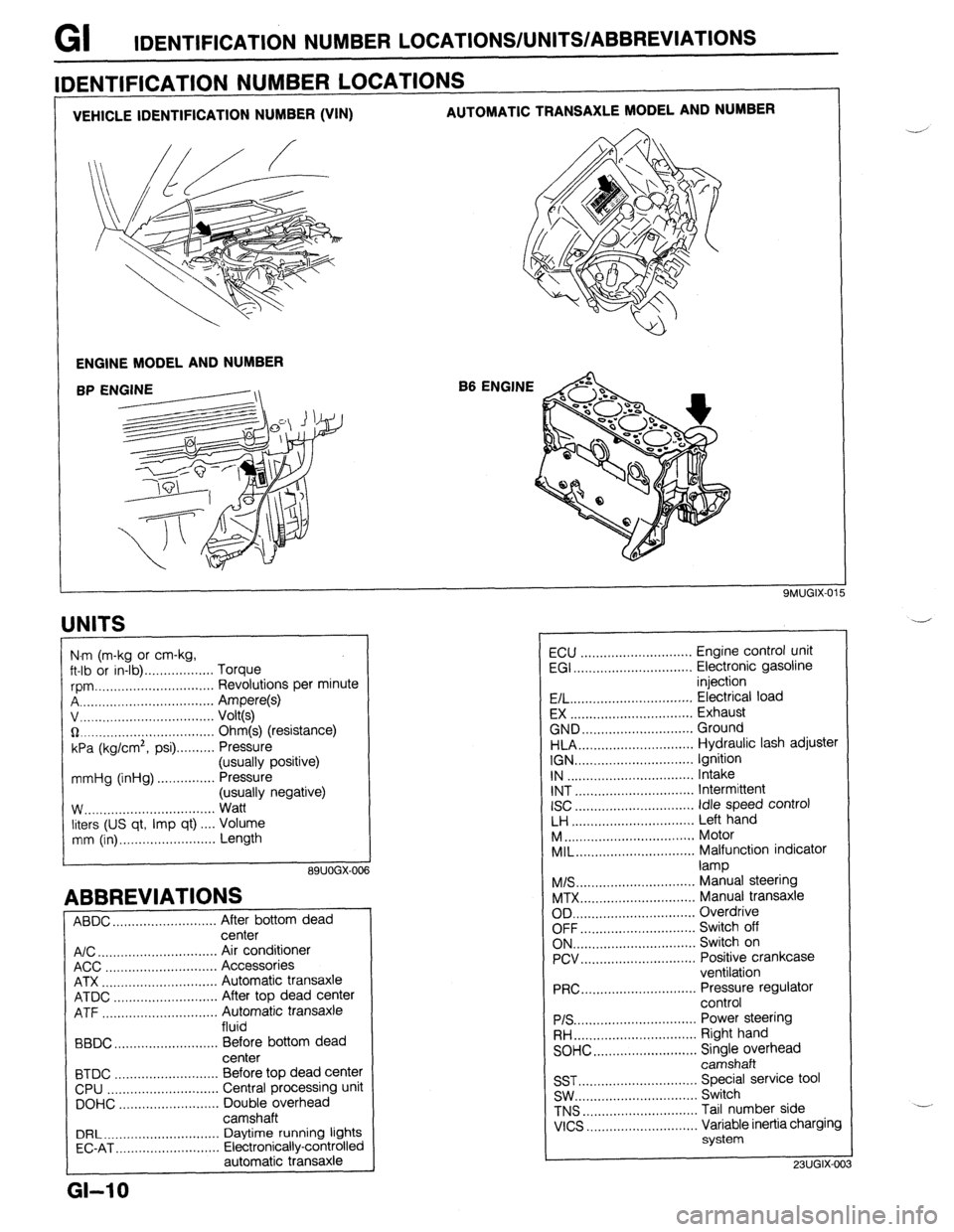
IDENTIFICATION NUMBER LOCATIONS
UNITS
I
N.m (m-kg or cm-kg,
ft-lb or in-lb) . . . . . . . . . . . . . . . . . . Torque
rpm ._..,,,.............,.......... Revolutions per minute
A . . . . . . . . . . . . . . . . . Ampere(s)
v, . . . . . . . . . . . . . .
Volt(s)
$2 _....._..,......................... Ohm(s) (resistance)
kPa (kg/cm2,
psi) . . . . . . . . . . Pressure
(usually positive)
mmHg (inHg) . . . . . . . . . . . . . . . Pressure
(usually negative)
W.. . . . . . . . . . . .
Watt
liters (US qt, Imp qt) ,... Volume
mm (in) ..,......,...,........... Length
89UOGX-00
ABBREVIATIONS
ABDC . . . . . . . . . . . . . . . . . . . . .
After bottom dead
center
A/C . . . . . . . . . . . . . . . . . . . . . . . . . . . . . . .
Air conditioner
ACC ..,.,...... 3 . . . . . . . . . . . . . . . . . Accessories
ATX . . . . . . . . . . . . . . . . . . . . . . . . . . . . . . Automatic transaxle
ATDC ..,,...,...,............... After top dead center
ATF . . . . . . . . . . . . . . . . . Automatic transaxle
fluid
BBDC ,,..,.......,...,......,... Before bottom dead
center
BTDC .,......,...............,.. Before top dead center
CPU ..,,.......,...,..........,.. Central processing unit
DOHC ..,...,..,............,,.. Double overhead
camshaft
DRL ____.......................... Daytime running lights
EC-AT .,_.......,............,,.. Electronically-controlled
automatic transaxle
L
GI-10
ECU ............................. Engine control unit
EGI ............................... Electronic gasoline
injection
E/L.. .............................. Electrical load
EX ................................ Exhaust
GND.. ........................... Ground
HLA.. ............................ Hydraulic lash adjuster
IGN ............................... Ignition
IN ................................. Intake
INT ............................... Intermittent
ISC
............................... idle speed control
LH ................................ Left hand
M..
................................ Motor
MIL..
............................. Malfunction indicator
lamp
M/S..
............................. Manual steering
MTX.. ............................ Manual transaxle
OD ................................ Overdrive
OFF.. ............................ Switch off
ON.. .............................. Switch on
PCV.. ............................ Positive crankcase
ventilation
PRC..
............................ Pressure regulator
control
PIS ................................ Power steering
RH..
.............................. Right hand
SOHC.. .........................
z;;kiprhead
SST ............................... Special service tool
SW.. .............................. Switch
TNS
.............................. Tail number side
VICS
............................. Variable inertia charging
system
23UGIX-00
Page 32 of 1164
INDEX
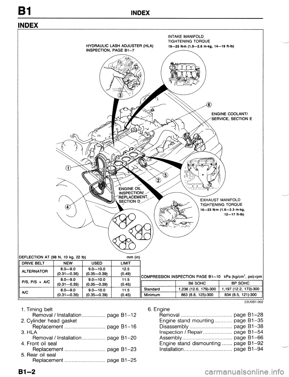
NDEX
INTAKE MANIFOLD,
TIGHTENING TORQUE
.-’ HYDRAULIC LASH ADJUSTER (HLA)
INSPECTION, PAGE Bl-7 19-25 N.m (1.9-2.6 m-kg, 14-19 ft-lb)
DEFLECTION AT (98 N, 10 kc
19
22 lb)
r “Y7 ENGINE COOLANT/
SECTION
EXHAUST MANIFOLD
TIGHTENING TORQUE
16-23 N.m (1.6-2.3 m-kg,
12-17 ft-lb
mm (in)
11 DRIVE BELT NEW USED LIMIT
COMPRESSION INSPECTION PAGE 61-10 kPa (kg/cm*, psi)-rpm
y-1, Sta,,dar‘-j , ,238;;;;;;$))-3(J() , ,,97;;2~;;&)0
883 (8.8, 125)-300 834 (8.5, 121)-300 II A/C 8.0-9.
(0.31-0.35) I (0.35-0.39) I (0.45) 11 Minimum
-
E
1. Timing belt
23UOBl-00:
Removal / installation . . . . . . . . . . . . . . . . page 61-l 2
2. Cylinder head gasket
Rep!acement . . . . . . . . . . . . . . . . . . . . . . . . . . . . page Bl-16
3. HLA
Removal / Installation . . . . . . . . . . . . . . . page 81-20
4. Front oil seal
Replacement . . . . . . . . . . . . . . . . . . . . . . . . . . . . page Bl -23
5. Rear oil seal Removal ................................... 6. Engine
page Bl-28
Engine stand mounting.. .......... page 81-35
Disassembly ............................. page Bl-38
Inspection / Repair .................... page Bl-54
Assembly.. ................................ page 81-66
Engine stand dismounting.. ..... page 81-92
Installation page 81-94 .+- .................................
Replacement . . , . . ,.. . . . . . . . . . . . . . . . . . . . page Bl-25
81-2
Page 37 of 1164
ENGINE TUNE-UP PROCEDURE Bl
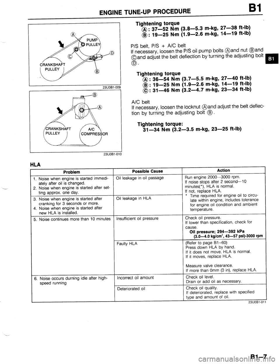
Tightening torque
@ : 37-52 N,m (3.8-5.3 m-kg, 27-38 ft-lb)
@ : 19-25 Nsm (1.9-2.6 m-kg, 14-19 ft-lb)
23UOBl-OC
P/S belt, P/S + A/C belt
If necessary, loosen the P/S oil pump bolts @and nut @and
Oand adjust the belt deflection by turning the adjusting bolt
0.
Tightening torque
@I : 36-54 N.m (3.7-5.5 m-kg, 27-40 ft-lb)
@ : 19-25 N#m (1.9-2.6 m-kg, 14-19 ft-lb)
0: 31-46 N-m (3.2-4.7 m-kg, 23-34 ft-lb)
A/C belt
If necessary, loosen the locknut @and adjust rhe belt deflec-
tion by turning the adjusting bolt @.
Tightening torque:
31-34 N-m (3.2-3.5 m-kg, 23-25 ft-lb)
1
HLA
Problem Possible Cause Action
1. Noise when engine is started immedi- Oil leakage in oil passage Run engine 2000-3000 rpm.
ately after oil is changed. If noise stops after 2 second-10
2. Noise when engine is started after set- minutes(*), HLA is normal.
ting approx. one day. If not, replace HLA.
3. Noise when engine is started after Oil leakage in HLA - * Time required for engine oil to circu-
cranking for 3 seconds or more. late within engine, includes tolerance
4. Noise when engine is started after for engine oil condition and ambient
new HLA is installed. temperature.
5. Noise continues more than 10 minutes Insufficient oil pressure Check oil pressure.
If lower than specification, check for
cause.
Oil pressure; 294-392 kPa
(3.0-4.0 kg/cm*, 43-57 psi)-3000 rpm
(Refer to page 81-60)
Press down HLA by hand.
If it does not move,. HLA is normal.
If it moves, replace HLA.
t
I
Measure valve clearance.
If more than Omm (0 in), replace HLA.
5. Noise occurs durning idle after high-
speed running Incorrect oil amount
Deteriorated oil Check oil level.
Drain or add oil as necessary.
Check oil quality.
If deteriorated, replace with specified
type and amount of oil.
23UOBl-01
Bl-7
Page 38 of 1164
Bl ENGINE TUNE-UP PROCEDURE
13UOBi-036
-i
OWOBX-261
13UOBl-08
LOCK BOLTS
IGNITION TIMING, IDLE SPEED
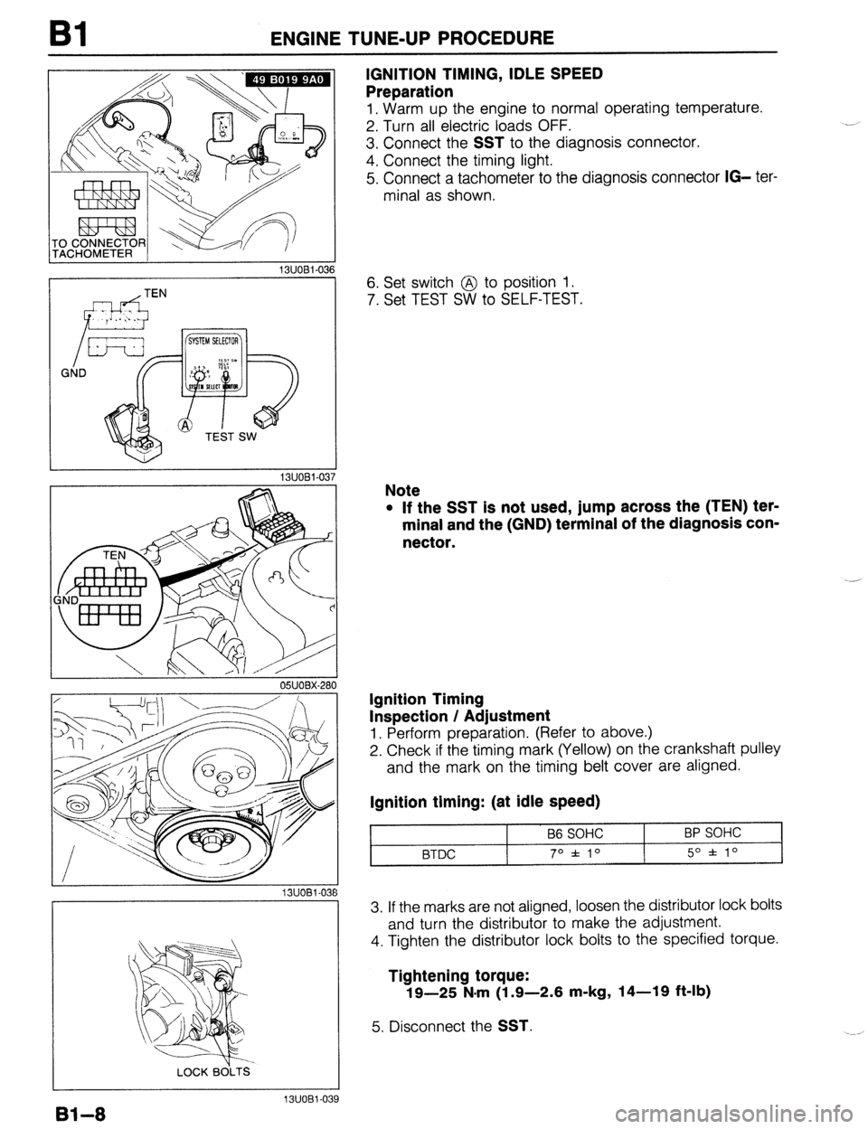
Preparation
1, Warm up the engine to normal operating temperature.
2. Turn all electric loads OFF.
3. Connect the
SST to the diagnosis connector.
4. Connect the timing light.
5. Connect a tachometer to the diagnosis connector
IG- ter-
minal as shown.
6. Set switch @ to position 1.
7. Set TEST SW to SELF-TEST.
Note
l If the SST is not used, jump across the (TEN) ter-
minal and the (GND) terminal of the diagnosis con-
nector.
Ignition Timing
Inspection / Adjustment
1. Perform preparation. (Refer to above.)
2. Check if the timing mark (Yellow) on the crankshaft pulley
and the mark on the timing belt cover are aligned.
Ignition timing: (at idle speed)
B6 SOHC
BTDC 70 f 10 BP SOHC
5O f lo
3. If the marks are not aligned, loosen the distributor lock bolts
and turn the distributor to make the adjustment.
4. Tighten the distributor lock bolts to the specified torque.
Tightening torque:
19-25 N.m (1.9-2.6 m-kg, 14-19 ft-lb)
5. Disconnect the SST.
Bl-8
13UOBl-039
Page 40 of 1164
Bl COMPRESSION
COMPRESSION
If the engine exhibits low power, poor fuel economy, or poor idle, check the following:
1. Ignition system (Refer to Section G.)
2. Compression
3. Fuel system (Refer to Section F.)
23UOBl-01
23UOBl-06
23UOBl-014 23UOBl-012
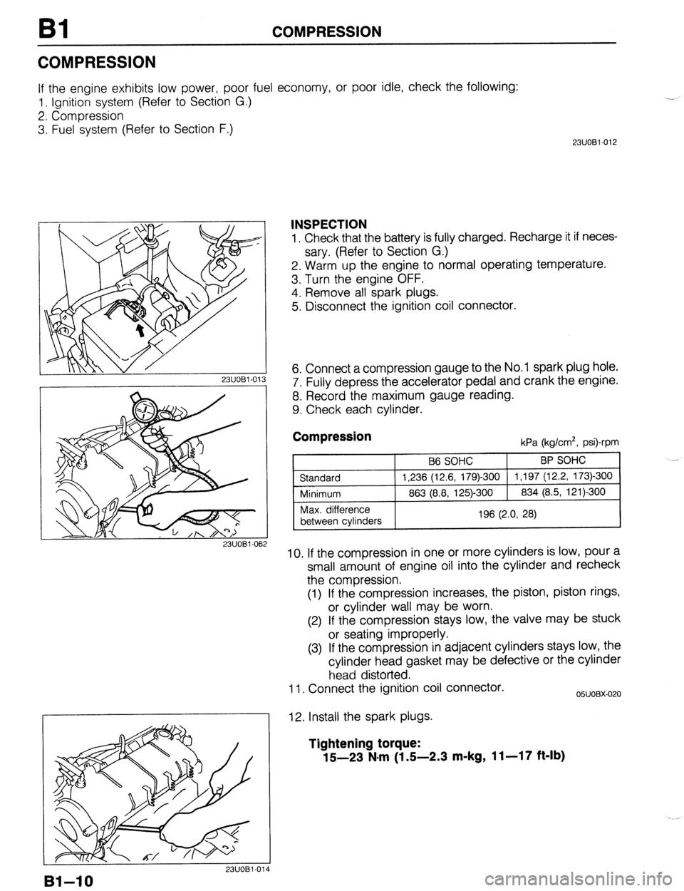
INSPECTION
1. Check that the battery is fully charged. Recharge it if neces-
sary. (Refer to Section G.)
2. Warm up the engine to normal operating temperature.
3. Turn the engine OFF.
4. Remove all spark plugs.
5. Disconnect the ignition coil connector.
6. Connect a compression gauge to the No. 1 spark plug hole.
7. Fully depress the accelerator pedal and crank the engine.
8. Record the maximum gauge reading.
9. Check each cylinder.
Compression kPa (kg/cm*, psi)-rpm
10. If the compression in one or more cylinders is low, pour a
small amount of engine oil into the cylinder and recheck
the compression.
(1) If the compression increases, the piston, piston rings,
or cylinder wall may be worn.
(2) If the compression stays low, the valve may be stuck
or seating improperly.
(3) If the compression in adjacent cylinders stays low, the
cylinder head gasket may be defective or the cylinder
head distorted.
11. Connect the ignition coil connector.
12. Install the spark plugs.
05UOBX-020
Tightening torque:
15-23 N*m (1 S-2.3 m-kg, 11-17 ft-lb)
Bl-10
Page 44 of 1164
Bl ON-VEHICLE MAINTENANCE
13EOBl-023
MARKS
13EOBl-02, 4
I
03UOBl-02
98 N
(10 kg, 22 lb)
13EOBl-02 15
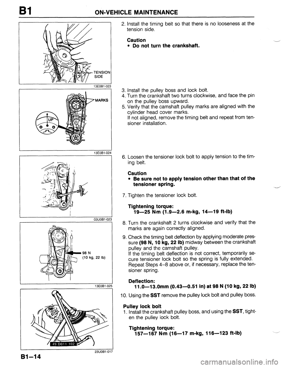
2. Install the timing belt so that there is no looseness at the
tension side.
Caution
l Do not turn the crankshaft. .-
3. Install the pulley boss and lock bolt.
4. Turn the crankshaft two turns clockwise, and face the pin
on the pulley boss upward.
5. Verify that the camshaft pulley marks are aligned with the
cylinder head cover marks.
If not aligned, remove the timing belt and repeat from ten-
sioner installation.
6. Loosen the tensioner lock bolt to apply tension to the tim-
ing belt.
Caution
l Be sure not to apply tension other than that of the
tensioner spring.
7. Tighten the tensioner lock bolt.
--
Tightening torque:
19-25 N,m (1.9-2.6 m-kg, 14-19 ft-lb)
8. Turn the crankshaft 2 turns clockwise and verify that the
marks are again correctly aligned.
9. Check the timing belt deflection by applying moderate pres-
sure (96 N,
10 kg, 22 lb) midway between the crankshaft
pulley and the camshaft pulley.
If the timing belt deflection is not correct, temporarily se-
cure tensioner lock bolt so the spring is fully extended.
Repeat Steps 4-8 above or, if necessary, replace the ten-
sioner spring.
Deflection:
11 .O-13.0mm (0.43-0.51 in) at 96 N (10 kg, 22 lb)
10. Using the SST remove the pulley lock bolt and pulley boss.
Pulley lock bolt
1. Install the crankshaft pulley boss, and using the SST, tight-
en the pulley lock bolt.
Tightening torque:
157-167 N,m (16-17 m-kg, 116-123 ft-lb)
91-14
Page 49 of 1164
.
ON-VEHICLE MAINTENANCE
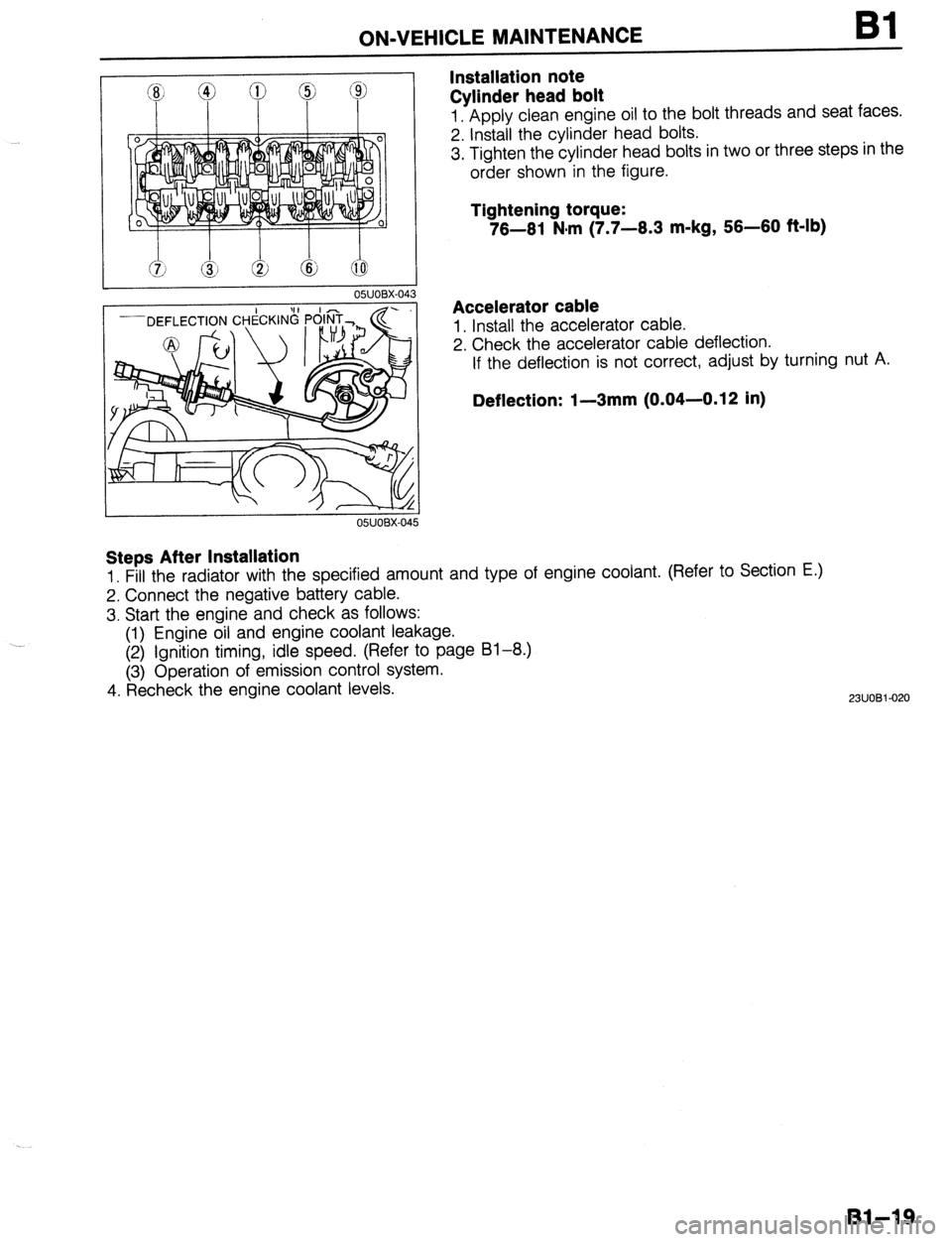
Installation note
Cylinder head bolt Bl
1. Apply clean engine oil to the bolt threads and seat faces.
2. Install the cylinder head bolts.
3. Tighten the cylinder head bolts in two or three steps in the
order shown in the figure.
Tightening torque:
76-61 N#m (7.7-6.3 m-kg, 56-60 f&lb)
Accelerator cable
1. Install the accelerator cable.
2. Check the accelerator cable deflection.
If the deflection is not correct, adjust by turning nut A.
Deflection: I-3mm (0.04-0.12 in)
Steps After Installation
1. Fill the radiator with the specified amount and type of engine coolant. (Refer to Section E.)
2. Connect the negative battery cable.
3. Start the engine and check as follows:
(1) Engine oil and engine coolant leakage.
(2) Ignition timing, idle speed. (Refer to page 81-8.)
(3) Operation of emission control system.
4. Recheck the engine coolant levels.
2311081-020
Bl-19
Page 52 of 1164

Bl ON-VEHICLE MAINTENANCE
8 e
93UOlA.08
EX
03UOBl-035
HEAD COVER
)
23UOBl-023
Steps After Installation
1, Connect the negative battery cable.
2. Start the engine and fully warm up.
3. Verify that there is no tappet noise. 2. Install the rocker arm and rocker shaft assembly.
Caution
l The bolts must be tightened gradually and in the or-
der shown in the figure.
Tightening torque:
22-28 N-m (2.2-2.9 m-kg, 18-21 ft-lb)
BP SOHC
1. Assemble the rocker arm and rocker shaft assembly as
shown in the figure.
Caution
l Face the rocker shaft identification mark upward.
l The installation bolt holes are different for the ex-
haust and intake sides.
Identification mark
IN . . . . . . . . . . White
EX . . . . . . . . . . . Blue
2. Install the rocker arm and rocker shaft assembly.
3. Tighten the rocker arm bolts in two or three steps in the or-
der shown in the figure.
Tightening torque:
22-28 Nsrn (2.2-2.9 m-kg, 16-21 ft-lb)
Cylinder head cover
1. Install the cylinder head cover.
Tightening torque
Bolt @:
4.9-8.8 N-m (50-90 cmikg, 43-78 in-lb)
Bolt @:
7.8-l 1 Nnrn (80-l 10 cm-kg, 69-95 in-lb)
Caution
l If the head cover gasket is reused, apply sealant in
the groove as shown.
03UOBl-038
.-
Bl-22