jump start MAZDA PROTEGE 1992 Workshop Manual
[x] Cancel search | Manufacturer: MAZDA, Model Year: 1992, Model line: PROTEGE, Model: MAZDA PROTEGE 1992Pages: 1164, PDF Size: 81.9 MB
Page 262 of 1164

E ELECTRIC COOLING FAN SYSTEM, FAN MOTOR
03UOEX-02
I
1
I
‘4
.
2
.:
)
SYSTEM INSPECTION
1. Jump across the fan test (TFA) terminal and the ground
(GND) terminal of the diagnosis connector.
2. Turn the ignition switch ON and verify that the fan operates.
If the fan does not operate, inspect the cooling fan system
components and wire harness. -.-
3. Remove the radiator cap and place a thermometer in the
radiator filler neck.
4. Start the engine.
5. Verify that the fan operates when the coolant temperature
reaches approx. 97OC (207OF).
If it does, check the water thermoswitch.
(Refer to page E-16.)
FAN MOTOR
INSPECTION
Single-Speed Type
1. Check that the battery is fully charged.
2. Disconnect the fan motor connector.
3. Connect the battery and an ammeter to the fan motor con-
nectar.
4. Verify that current is as specified.
Current (A)
B6 SOHC
BP SOHC
BP DOHC MTX ATX
6.6 f 1 6.6 f 1
6.6 f 1 -
6.6 f 1 -
5. If current is not within specification and/or the fan does not
turn smoothly, replace the fan motor.
Two-Speed Type
1. Check that the battery is fully charged.
2. Disconnect the fan motor connector.
3. Connect the battery and an ammeter to the fan motor con-
nectors for low-speed inspection. 4. Verify that the fan motor operates smoothly at the standard
current.
Current (A): 8.8 + 10% MAX
I
03UOEX-022
E-14
Page 296 of 1164
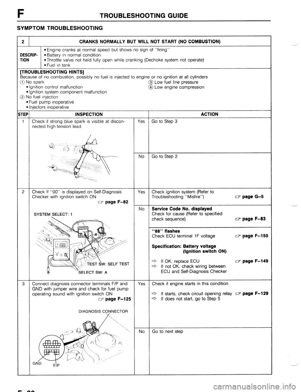
F TROUBLESHOOTING GUIDE
SYMPTOM TROUBLESHOOTING
2 CRANKS NORMALLY BUT WILL NOT START (NO COMBUSTION)
l Engine cranks at normal speed but shows no sign of “firing”
DESCRIP-
*Battery in normal condition
TION
*Throttle valve not held fully open while cranking (Dechoke system not operate)
*Fuel in tank [TROUBLESHOOTING HINTS]
Because of no combustion, possibly no fuel is injected to engine or no ignition at all cylinders
:I) No spark
@I Low fuel line pressure
l Ignition control malfunction
@ Low engine compression l Ignition system component malfunction
3 No fuel injection
l Fuel pump inoperative l Injectors inoperative
TEP INSPECTION
ACTION
1 Check if strong blue spark is visible at discon-
Yes Go to Step 3
netted high-tension lead
No Go to Step 2
2 Check if “00” is displayed on Self-Diagnosis
Yes Check ignition system (Refer to
Checker with ignition switch ON
Troubleshooting “Misfire”) w page G-5
w page F-82
No Service Code No. displayed
Check for cause (Refer to specified
check sequence) w page F-83
“88” flashes
Check ECU terminal 1F voltage w page F-150
Specification: Battery voltage
(Ignition switch ON)
W: SELF TEST e If OK, replace ECU w page F-149 c3 If not OK, check wiring between
SELECT SW: A ECU and Self-Diagnosis Checker
3 Connect diagnosis connector terminals F/P and
Yes Check if engine starts in this condition
GND with jumper wire and check for fuel pump
operating sound with ignition switch ON c3 If starts, check circuit opening relay c7 page F-129
w page F-125
c3 If does not start, go to Step 5
DIAGNOSIS C
Go to next step ._-,
._. ,
F-30
Page 307 of 1164

TROUBLESHOOTING GUIDE
iTEP INSPECTION ACTION
5 Warm-up engine to normal operating tempera-
Yes Change fuel to another brand
ture and stop it
Connect diagnosis connector terminals F/P and
GND with jumper wire for 3 minutes with ignition
switch ON, then check if engine starts easily
DIAGNOSIS CONNECTOR No
Go to next step
G
F/P 6
Try known good ECU and check if condition
Yes Replace ECU w page F-149 improves w page F-149 No
Change fuel to another brand
23UOFX-02:
F-41
Page 387 of 1164
FUEL PUMP CONNECTOR
/
REAR SEAT C
FUEL SYSTEM F
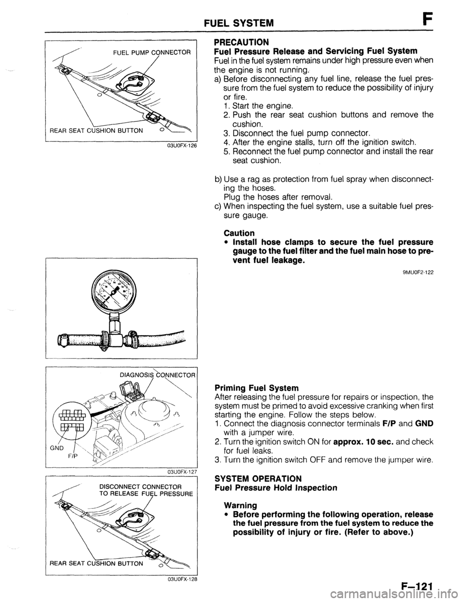
PRECAUTION
Fuel Pressure Release and Servicing Fuel System
Fuel in the fuel system remains under high pressure even when
the engine is not running.
a) Before disconnecting any fuel line, release the fuel pres-
sure from the fuel system to reduce the possibility of injury
or fire.
1. Start the engine.
2. Push the rear seat cushion buttons and remove the
cushion.
3. Disconnect the fuel pump connector.
4. After the engine stalls, turn off the ignition switch.
5. Reconnect the fuel pump connector and install the rear
seat cushion.
b) Use a rag as protection from fuel spray when disconnect-
ing the hoses.
Plug the hoses after removal.
c) When inspecting the fuel system, use a suitable fuel pres-
sure gauge.
Caution
l Install hose clamps to secure the fuel pressure
gauge to the fuel filter and the fuel main hose to pre-
vent fuel leakage.
9MUOF2-122 OBUOFX-126
DlAGNOS&O,NNECTOR
03UOFX-12.
-
DISCONNECT CONNECTOR
/ TO RELEASE FUEL PRESSURE
03UOFX-12;
Priming Fuel System
After releasing the fuel pressure for repairs or inspection, the
system must be primed to avoid excessive cranking when first
starting the engine. Follow the steps below.
1. Connect the diagnosis connector terminals
F/P and GND
with a jumper wire.
2. Turn the ignition switch
ON for approx. 10 sec. and check
for fuel leaks.
3. Turn the ignition switch OFF and remove the jumper wire.
SYSTEM OPERATION
Fuel Pressure Hold Inspection
Warning
l Before performing the following operation, release
the fuel pressure from the fuel system to reduce the
possibility of injury or fire. (Refer to above.)
F-121
Page 401 of 1164
PRESSUREREGULATORCONTROLSYSTEM F
03UOFX-17
*
03UOFX-14!
OSUOFX-17
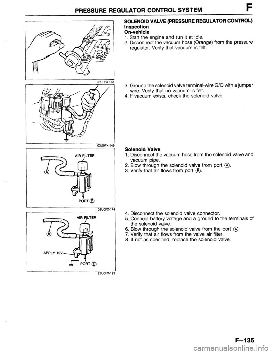
SOLENOID VALVE (PRESSURE REGULATOR CONTROL)
Inspection
On-vehicle
1. Start the engine and run it at idle.
2. Disconnect the vacuum hose (Orange) from the pressure
regulator. Verify that vacuum is felt.
3. Ground the solenoid valve terminal-wire G/O with a jumper
wire. Verify that no vacuum is felt.
4. If vacuum exists, check the solenoid valve.
Solenoid Valve
1. Disconnect the vacuum hose from the solenoid valve and
vacuum pipe.
2. Blow through the solenoid valve from port @
3. Verify that air flows from port @.
4. Disconnect the solenoid valve connector.
5. Connect battery voltage and a ground to the terminals of
the solenoid valve.
6. Blow through the solenoid valve from the port @.
7. Verify that air flows from the valve air filter.
8. If not as specified, replace the solenoid valve.
F-l 35
Page 917 of 1164
WARNING SYSTEM T
13UOTX-07
63U15X-05
, I//
‘nF -
-
-
FUEL
13UOTX.08C
- CHARGE
13UOTX-08
13UOTX-08
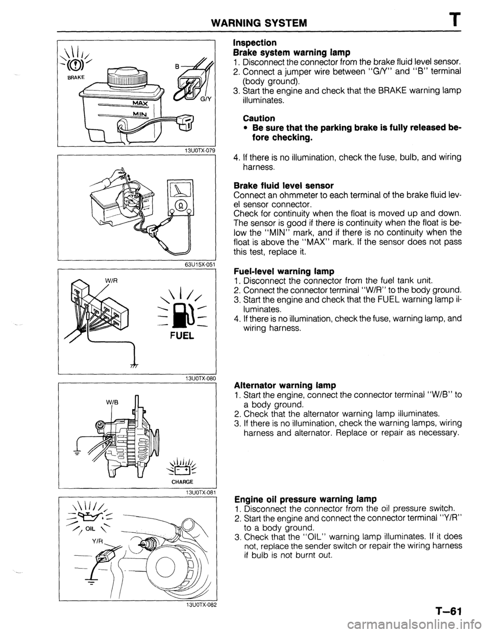
Inspection
Brake system warning lamp
1. Disconnect the connector from the brake fluid level sensor.
2. Connect a jumper wire between “G/Y” and “6” terminal
(body ground).
3. Start the engine and check that the BRAKE warning lamp
illuminates.
Caution
l Be sure that the parking brake is fully released be-
fore checking.
4. If there is no illumination, check the fuse, bulb, and wiring
harness.
Brake fluid level sensor
Connect an ohmmeter to each terminal of the brake fluid lev-
el sensor connector.
Check for continuity when the float is moved up and down.
The sensor is good if there is continuity when the float is be-
low the “MIN” mark, and if there is no continuity when the
float is above the “MAX” mark. If the sensor does not pass
this test, replace it.
Fuel-level warning lamp
1. Disconnect the connector from the fuel tank unit.
2. Connect the connector terminal “W/R” to the body ground.
3. Start the engine and check that the FUEL warning lamp il-
luminates.
4. If there is no illumination, check the fuse, warning lamp, and
wiring harness.
Alternator warning lamp
1. Start the engine, connect the connector terminal “W/B” to
a body ground.
2. Check that the alternator warning lamp illuminates.
3. If there is no illumination, check the warning lamps, wiring
harness and alternator. Replace or repair as necessary.
Engine oil pressure warning lamp
1. Disconnect the connector from the oil pressure switch.
2. Start the engine and connect the connector terminal “Y/R”
to a body ground.
3. Check that the “OIL” warning lamp illuminates. If it does
not, replace the sender switch or repair the wiring harness
if bulb is not burnt out.
T-61
Page 918 of 1164
T
I WARNING SYSTEM
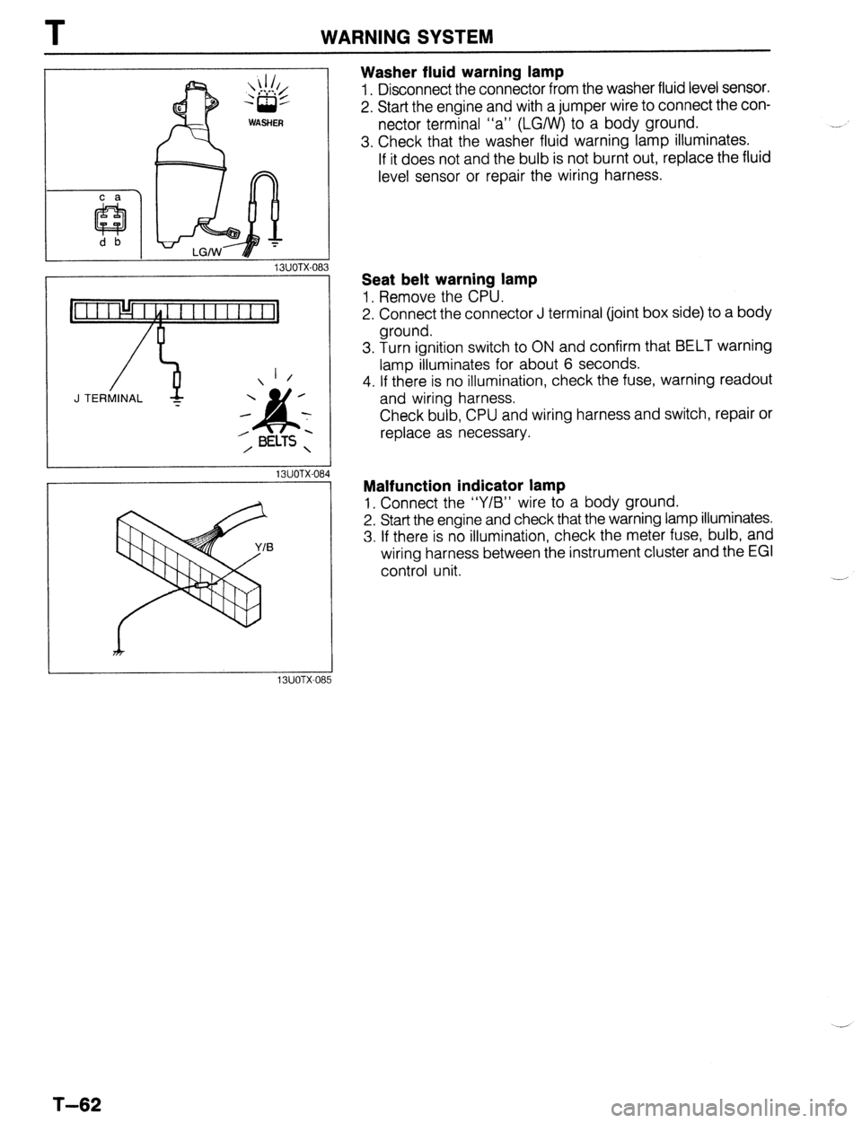
Washer fluid warning lamp
1. Disconnect the connector from the washer fluid level sensor.
2. Start the engine and with a jumper wire to connect the con-
nector terminal “a” (LGIW) to a body ground.
3. Check that the washer fluid warning lamp illuminates.
If it does not and the bulb is not burnt out, replace the fluid
level sensor or repair the wiring harness.
13UOTX-08
_-
1 /
J TERMINAL -
13UOTX-08
13UOTX-08
Seat belt warning lamp
1, Remove the CPU.
2. Connect the connector J terminal (joint box side) to a body
ground.
3. Turn ignition switch to ON and confirm that BELT warning
lamp illuminates for about 6 seconds.
4. If there is no illumination, check the fuse, warning readout
and wiring harness.
Check bulb, CPU and wiring harness and switch, repair or
replace as necessary.
Malfunction indicator lamp
1, Connect the “Y/B” wire to a body ground.
2. Start the engine and check that the warning lamp illuminates.
3. If there is no illumination, check the meter fuse, bulb, and
wiring harness between the instrument cluster and the EGI
control unit.
T-62
Page 1069 of 1164
Troubleshooting Z-Gl-13
el
-
Ill
31
-
I1
Jl
:n
r.
7a
ver
le
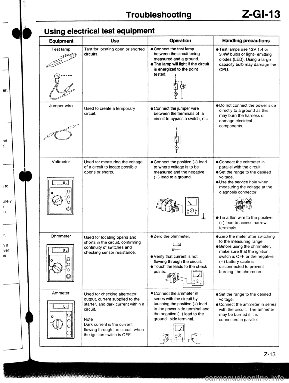
Usina electrical test eaubment -----w - I - Equipment Use Operation Handling precautions
Test lamp Test for locating open or shorted l Connect the test lamp
0 Test lamps use 12V 1.4 or
R circuits. between the circuit being
3.4W bulbs or light- emitting
measured and a ground.
diodes (LED). Using a large
*The
lamp will light if the circuit
capacity bulb may damage the
is energized to the point
CPU.
,.WD,.l
b tested.
Jumper wire
Used to create a temporary l Connect the jumper wire 0 Do not connect the power side
circuit. between the terminals of a directly to a ground as this
circuit to bypass a switch, etc. may burn the harness or
damage electrical
/d<;>‘-
d components.
I
n
Voltmeter
Used for measuring the voltage
l Connect the positive (+) lead l Connect the voltmeter In
of a circuit to locate possible to where voltage is to be parallel with the circuit.
opens or shorts. measured and the negative
0 Set the range to the desired
(- ) lead to a ground. voltage.
l Use the service hole when
measuring the voltage at the
diagnosis connector.
~Tie a thin wire to the posrtive
(+) lead to access narrow
terminals.
Ohmmeter
Ammeter Used for locating opens and
l Zero the ohmmeter. *Zero the meter after switching
shorts in the circuit, confirming
I to the measuring range.
continuity of switches and
checking sensor resistance. &.--
l Before using the ohmmeter,
make sure that the ignition
l Verify that current is not switch is OFF or the negative
flowing through the circuit. (- ) battery cable is
0 Touch the leads to the check disconnected to prevent
points.* burning the ohmmeter.
Used for checking alternator
l Connect the ammeter in l Set the range to the desired
output, current supplied to the series with the circuit by
voltage.
starter, and dark current within a touching the positive (+) lead
l Connect the ammeter in series
circuit. to the power side terminal and
with the circuit. The ammeter
the negative (- ) lead to the
may be burned If it is
Note ground- side terminal.
connected in parallel.
Dark current is the current
flowing through the circuit when
the Ignition switch is OFF.