key battery MAZDA PROTEGE 1992 Workshop Manual
[x] Cancel search | Manufacturer: MAZDA, Model Year: 1992, Model line: PROTEGE, Model: MAZDA PROTEGE 1992Pages: 1164, PDF Size: 81.9 MB
Page 54 of 1164

Bl ON-VEHICLE MAINTENANCE
01 EOBX-056
23UOBi -0:
Steps After Installation
1. Lower the vehicle.
2. Connect the negative battery cable.
3. Start the engine and check the ignition timing.
(Refer to page 61-8)
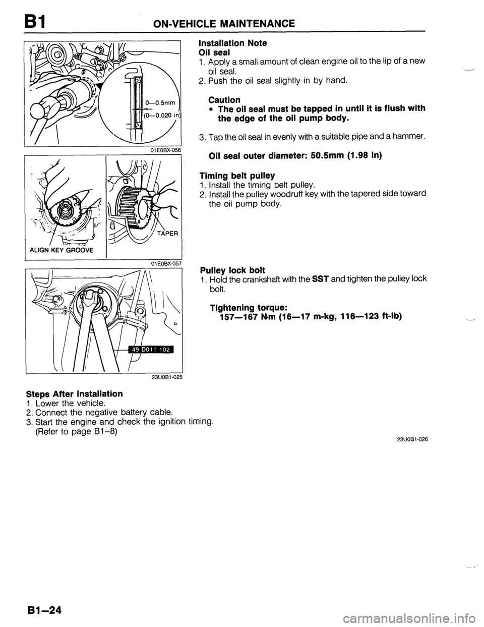
Installation Note
Oil seal
1. Apply a small amount of clean engine oil to the lip of a new
oil seal.
2. Push the oil seal slightly in by hand.
Caution
l The oil seal must be tapped in until it is flush with
the edge of the oil pump body.
3. Tap the oil seal in evenly with a suitable pipe and a hammer.
Oil seal outer diameter: 50.5mm (1.98 in)
Timing belt pulley
1. Install the timing belt pulley.
2. Install the pulley woodruff key with the tapered side toward
the oil pump body.
Pulley lock bolt
1. Hold the crankshaft with the SST and tighten the pulley lock
bolt.
Tightening torque:
157-167 N*rn (16-17 m-kg, 116-123 ft-lb)
23UOBi-026
Bl-24
Page 159 of 1164

ON-VEHICLE MAINTENANCE
I 05UOBX-063
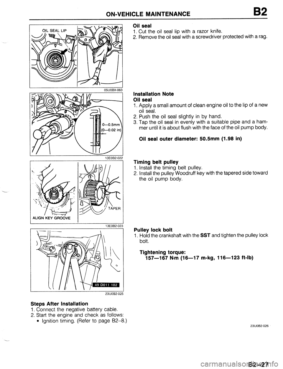
Oil seal
1. Cut the oil seal lip with a razor knife.
2. Remove the oil seal with a screwdriver protected with a rag.
13EOB2-02
ALIGN.KEY GRCi&E
13EOB2-02
23UOB2-025
Steps After Installation
1. Connect the negative battery cable.
2. Start the engine and check as follows:
l Ignition timing. (Refer to page 92-8.)
3
Installation Note
Oil seal
1. Apply a small amount of clean engine oil to the lip of a new
oil seal.
2. Push the oil seal slightly in by hand.
3. Tap the oil seal in evenly with a suitable pipe and a ham-
mer until it is about flush with the face of the oil pump body.
Oil seal outer diameter: 50.5mm (1.98 in)
Timing belt pulley
1. Install the timing belt pulley.
2. Install the pulley Woodruff key with the tapered side toward
the oil pump body.
Pulley lock bolt
1. Hold the crankshaft with the SST and tighten the pulley lock
bolt.
Tightening torque:
157-187 N.m (18-17 m-kg, 116-123 ft-lb)
23UOB2-026
82-27
Page 907 of 1164

INTERIOR LAMP SYSTEM T
IG key illumination does not operate
Check room IOA fuse NG
- Short circuit
0 OK
Confirm battery voltage on V Defective harness (Fuse - Joint box), or bulb
0 OK
Confirm continuity on B wire of the joint box (CPU) to
ground Repair harness (Joint box - Body ground)
OK
When any door is opened, confirm that interior lamp
comes on
OK NG
~ Defective harness (Joint box - Door switch), or door
switch
Confirm continuity between N terminal of JB-09 connec- _ NG
-
tor and B terminal of JB-03 connector Repair harness (JB-09 - JB-03)
I OK
Replace CPU
23UOTX-029
Inspection
Door switch (Front sides with passive belt)
Confirm continuity between the R/W wire and the B wire of
the door switch connector (in passive motor connector).
Condition Continuity
Push X
Not push 0
0: Indicates continuity X: No continuity
03UOTX-181 Door switch (Others)
Confirm for continuity between the terminals of the door switch.
Condition Continuity
Push X
Not push 0
0: Indicates continuity X: No continuity
1 I OSJOTX-082
T-51
Page 913 of 1164

CENTRAL PROCESSING UNIT (CPU) T
Inspection
1. Remove the CPU and check the voltage or continuity between terminals of joint box and a body ground.
Ve: Battery voltage
Terminal
A Connected to Test condition Specification
B Rear wiper motor Ignition switch
Va
Light switch ON (first and second position) V0
C TNS switch
Light switch OFF ov
Seat belt buckled Ofi
D Seat belt buckle switch
Seat belt unbuckled
co
E
Rear wiper switch ON
OCI
F
Rear wiper switch
Rear wiper switch OFF
co
Rear washer switch ON 00
G Rear washer switch
Rear washer switch OFF
00
H
Key reminder switch ON
Va
I Key reminder switch
Key reminder switch OFF
ov
Ignition switch OFF ov
J Seat belt warning lamp
Ignition switch ON
VB
K Ground Constant
ov
L IG key illumination Constant
VB
For 5 seconds after ign. switch ON and belt unbuckled
00
M Passive shoulder belt
Other conditions
00
All doors closed
Va
N Door switch
Any door open
ov
0 Battery Constant VB
P Ignition switch
ignition switch ON V0
23UOTX-031
T-57
Page 914 of 1164

T WARNING SYSTEM
WARNING SYSTEM
WARNING BUZZER AND TIMER
Circuit Diagram
WARNING LAMP
REAR WIPER SW
RASSIVE CONTROL UNIT
Inspection
Remove the CPU and check the voltage or continuity between terminals of joint box and a body ground.
Key reminder alarm does not sound.
VB: Battery voltage
Terminal Connected to Test condition Specification To correct
I
Key reminder switch Key in cylinder VB Check ignition switch and
(ignition switch) Key out bf cylinder ov wiring harness
(Refer to page T-21)
P Ignition switch Ignition switch ON
‘/B Check ignition switch and
wiring harness
(Refer to page T-21)
N Door switch Any door open ov Check door switches and
All doors closed VS wiring harness
(Refer to page T-51)
23UOTX-031
T-58
Page 915 of 1164

WARNING SYSTEM
Light-off reminder alarm does not sound.
VB: Battery voltage
Terminal Connected to Test condition Specification To correct
C Headlight switch Headlight switch ON VB Check headlight switch and
wiring harness
(Refer to pages T-27, 28)
P Ignition switch Ignition switch ON VB Check ignition switch and
wiring harness
(Refer to page T-21)
N Door switch Any door open ov Check door switches and
All doors closed V0 wiring harness
(Refer to page T-51)
23UOTX-033
Seat belt alarm does not sound.
VB: Battery voltage
Terminal Connected to Test condition Specification To correct
P ignition switch Ignition switch ON
Vs Check ignition switch and
wiring harness
(Refer to page T-21)
D Seat belt buckle switch Seat belt buckled
00 Check seat belt buckle switch
Seat belt unbuckled
00 and wiring harness
(Refer to page S-102)
23UOTX-034
Seat belt timer does not operate.
VB: Battery voltage
Terminal Connected to Test condition Specification To correct
P Ignition switch Ignition switch ON VE Check ignition switch and
wiring harness
(Refer to page T-21)
23UOTX-035
Passive shoulder belt alarm does not sound.
VB: Battery voltage
Connected to Test condition
Ignition switch Ignition switch Specification
VB
Passive shoulder belt
control unit For 5 seconds after
ignition switch and belt
unbuckled
Other conditions 00
co
IG key illumination timer does not operate.
To correct
I
Check ignition switch and
wiring harness
(Refer to page T-21)
Check passive shoulder belt
control unit and wiring harness
(Refer to page S-104)
23UOTX-036
Ve: Battery voltage
Terminal Connected to Test condition Specification To correct
L IG key illumination Either door open
VB Check bulbs and wiring
harness
N Door switch Any door open ov Check door switches and
All doors closed
VB wiring harness
(Refer to page T-51)
23UOTX-037
T-59