service MAZDA PROTEGE 1992 Owner's Manual
[x] Cancel search | Manufacturer: MAZDA, Model Year: 1992, Model line: PROTEGE, Model: MAZDA PROTEGE 1992Pages: 1164, PDF Size: 81.9 MB
Page 259 of 1164

WATER PUMP WATER PUMP
E
REMOVAL / INSTALLATION
Caution
l Do not disassemble the water pump. If a problem is found, replace the pump as a Unit.
1. Disconnect the negative battery cable.
2. Drain the engine coolant.
3. Remove in the order shown in the figure, referring to
Removal Note.
4. Install in the reverse order of removal.
B6 SOHC AND BP SOHC
83, t B6, BP SOHC
I
I
L-----------------_-- ------- -1
/ \/
19-26 (1.9-2.6, 14-19) LVVVLI. YY,
1. Timing belt 4. Water pump assembly
Service ., . . .., ,, ., . . . . . ,. ,.,. ., ,., . . ,,.... . . . . , Section Bl Inspect for cracks, damaged mounting
2. Water inlet pipe
and gasket surface, bearing condition, and leakage
3. Water bypass pipe and O-ring 5. Water pump gasket
E-l 1
Page 260 of 1164

BP DOHC
L 7.8-11 N-m (60-110 cm-kg, 69-95 in-lb)
E WATER PUMP
157-167
I
(W-17, 116-123) I
I
/
I
I
I
---N-w------
---------------
----_---_
-I
N.m (m-kg, ft-lb) 1
^^, *--., ^^^
1. Timing belt
Service . . . . . . . . . . . . . . . . . . . . . . . . . . . . . . . . . . . . . . . . Section 5. Water pump assembly
B2
2. Water inlet pipe and gasket Inspect for cracks, damaged mounting
3. Water bypass pipe and O-ring surface, bearing condition, and leakage
4. Oil dip stick pipe bracket 6. Water pump gasket
Steps After Installation
1. Fill the radiator with the specified amount and type of engine coolant. (Refer to page E-6.)
2. Connect the negative battery cable,
3. Start the engine and check for leaks.
03UOEX-018
E-12
Page 268 of 1164

F INDEX
DlSTRhUTOR
SERVICE, SECTION G INHIBITOR SWITCH (ATX)
SERVICE, SECTION K
F-2
Page 282 of 1164

F OUTLINE
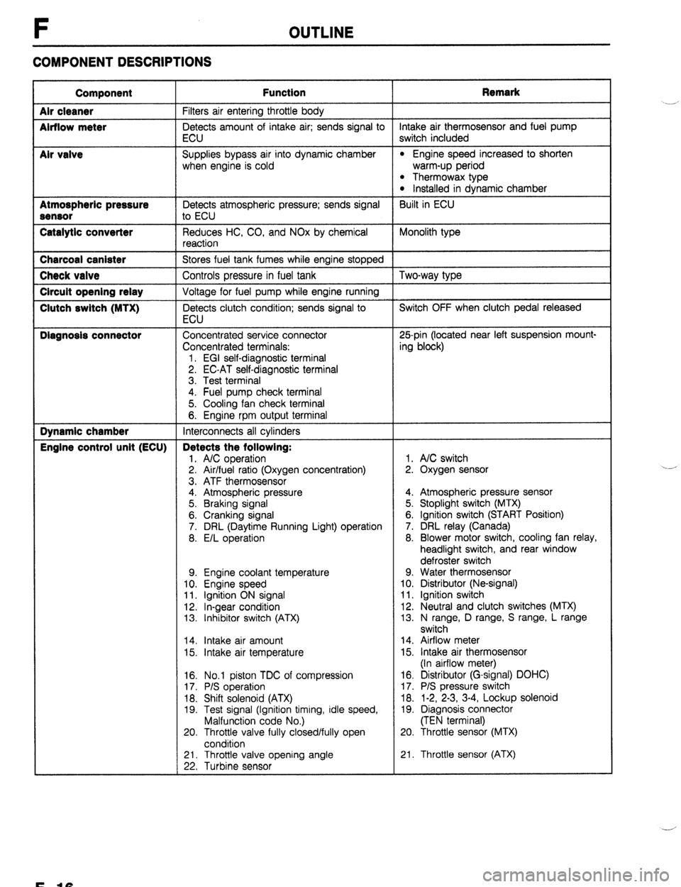
COMPONENT DESCRIPTIONS
Component
Air cleaner
Airflow meter
Mr valve
Atmospheric pressure
Sensor
Catalytic converter Function Remark
Filters air entering throttle body
Detects amount of intake air; sends signal to intake air thermosensor and fuel pump
ECU switch included
Supplies bypass air into dynamic chamber
l Engine speed increased to shorten
when engine is cold warm-up period
l Thermowax type l Installed in dynamic chamber
Detects atmospheric pressure; sends signal Built in ECU
to ECU
Reduces HC, CO, and NOx by chemical Monolith type
reaction Charcoal canister
Stores fuel tank fumes while engine stopped Check valve
Controls pressure in fuel tank Two-way type Circuit opening relay
Voltage for fuel pump while engine running Clutch switch (MTX)
Detects clutch condition; sends signal to Switch OFF when clutch pedal released
ECU Diagnosis connector
Concentrated service connector 25pin (located near left suspension mount-
Concentrated terminals: ing block)
1. EGI self-diagnostic terminal
2. EC-AT self-diagnostic terminal
3. Test terminal
4. Fuel pump check terminal
5. Cooling fan check terminal
6. Engine rpm output terminal Dynamic chamber
Interconnects all cylinders Engine control unit (ECU) Detects the following:
1. A/C operation 1. A/C switch
2. Air/fuel ratio (Oxygen concentration) 2. Oxygen sensor
3. ATF thermosensor
4. Atmospheric pressure 4. Atmospheric pressure sensor
5. Braking signal 5. Stoplight switch (MTX)
6. Cranking signal 6. Ignition switch (START Position)
7. DRL (Daytime Running Light) operation 7. DRL relay (Canada)
8. E/L operation 8. Blower motor switch, cooling fan relay,
headlight switch, and rear window
defroster switch
9. Engine coolant temperature 9. Water thermosensor
10. Engine speed 10. Distributor (Ne-signal)
11. Ignition ON signal 11. Ignition switch
12. In-gear condition 12. Neutral and clutch switches (MTX)
13. Inhibitor switch (ATX) 13. N range, D range, S range, L range
switch
14. Intake air amount 14. Airflow meter
15. Intake air temperature 15. Intake air thermosensor
(In airflow meter)
16. No.1 piston TDC of compression
17. P/S operation
18. Shift solenoid (ATX)
19. Test signal (Ignition timing, idle speed,
Malfunction code No.)
20. Throttle valve fully closed/fully open
condition 16. Distributor (G-signal) DOHC)
17. P/S pressure switch
18. 1-2, 2-3, 3-4, Lockup solenoid
19. Diagnosis connector
(TEN terminal)
20. Throttle sensor (MTX)
21. Throttle valve opening angle
22. Turbine sensor 21. Throttle sensor (ATX) .__r
F-10
Page 296 of 1164

F TROUBLESHOOTING GUIDE
SYMPTOM TROUBLESHOOTING
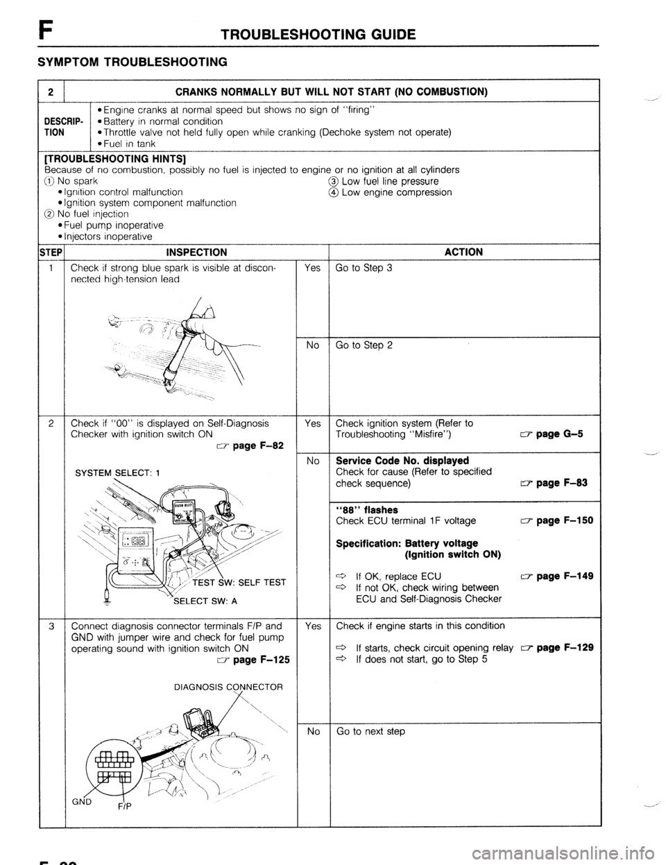
2 CRANKS NORMALLY BUT WILL NOT START (NO COMBUSTION)
l Engine cranks at normal speed but shows no sign of “firing”
DESCRIP-
*Battery in normal condition
TION
*Throttle valve not held fully open while cranking (Dechoke system not operate)
*Fuel in tank [TROUBLESHOOTING HINTS]
Because of no combustion, possibly no fuel is injected to engine or no ignition at all cylinders
:I) No spark
@I Low fuel line pressure
l Ignition control malfunction
@ Low engine compression l Ignition system component malfunction
3 No fuel injection
l Fuel pump inoperative l Injectors inoperative
TEP INSPECTION
ACTION
1 Check if strong blue spark is visible at discon-
Yes Go to Step 3
netted high-tension lead
No Go to Step 2
2 Check if “00” is displayed on Self-Diagnosis
Yes Check ignition system (Refer to
Checker with ignition switch ON
Troubleshooting “Misfire”) w page G-5
w page F-82
No Service Code No. displayed
Check for cause (Refer to specified
check sequence) w page F-83
“88” flashes
Check ECU terminal 1F voltage w page F-150
Specification: Battery voltage
(Ignition switch ON)
W: SELF TEST e If OK, replace ECU w page F-149 c3 If not OK, check wiring between
SELECT SW: A ECU and Self-Diagnosis Checker
3 Connect diagnosis connector terminals F/P and
Yes Check if engine starts in this condition
GND with jumper wire and check for fuel pump
operating sound with ignition switch ON c3 If starts, check circuit opening relay c7 page F-129
w page F-125
c3 If does not start, go to Step 5
DIAGNOSIS C
Go to next step ._-,
._. ,
F-30
Page 302 of 1164

F TROUBLESHOOTING GUIDE
5
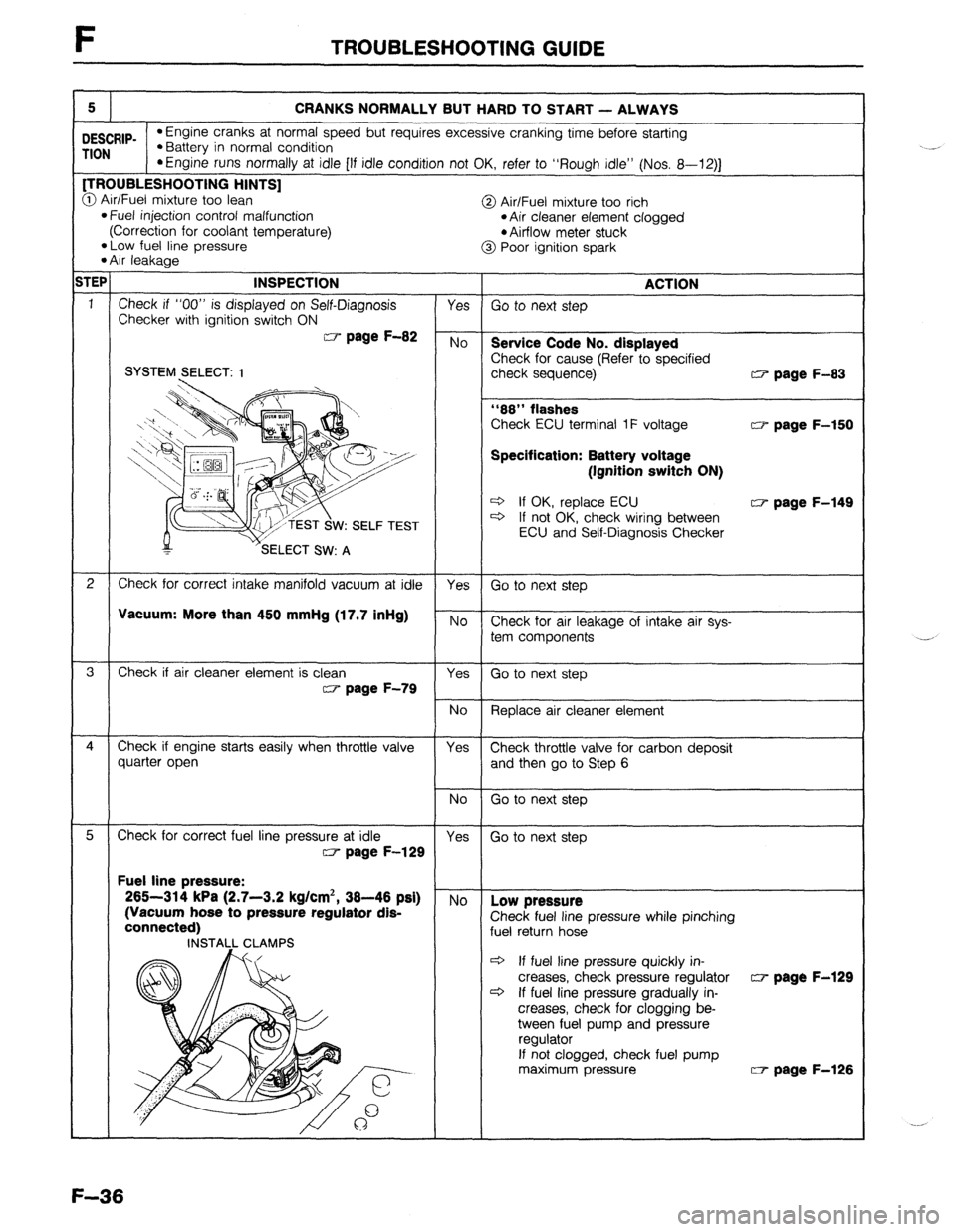
CRANKS NORMALLY BUT HARD TO START - ALWAYS
DESCRIP- l Engine cranks at normal speed but requires excessive cranking time before starting
TION l Battery in normal condition
*Engine runs normally at idle [If idle condition not OK, refer to “Rough idle” (Nos. 8-12)J [TROUBLESHOOTING HINTS]
@ Air/Fuel mixture too lean
@ Air/Fuel mixture too rich l Fuel injection control malfunction
(Correction for coolant temperature) *Air cleaner element clogged
l Airflow meter stuck
*Low fuel line pressure
l Air leakage @ Poor ignition spark
;TEP INSPECTION ACTION
1
Check if “00” is displayed on Self-Diagnosis Yes Go to next step
Checker with ignition switch ON W page F-82 No
Service Code No. displayed
Check for cause (Refer to specified SYSTEM SELECT: 1 check sequence) w page F-83
“88” flashes
Check ECU terminal 1F voltage w page F-150
Specification: Battery voltage
(Ignitlon switch ON)
* If OK, replace ECU w page F-149
W: SELF TEST c3 If not OK, check wiring between
ECU and Self-Diagnosis Checker
2 Check for correct intake manifold vacuum at idle
Yes Go to next step
VsCUUm: More than 450 mmHg (17.7 inHg) No Check for air leakage of intake air sys-
tem components
3 Check if air cleaner element is clean
Yes Go to next step w page F-79
No
Replace air cleaner element
4 Check if engine starts easily when throttle valve Yes Check throttle valve for carbon deposit
quarter open and then go to Step 6 Fuel line pressure:
265-314 kPa (2.7-3.2 kg/cm*, 38-46 psi)
(Vacuum hose to pressure regulator dis-
pressure while pinching
c3 If fuel line pressure quickly in-
creases, check pressure regulator w page F-129
c3 If fuel line pressure gradually in-
creases, check for clogging be-
tween fuel pump and pressure
If not clogged, check fuel pump
maximum pressure W- page F-126
F-36
Page 308 of 1164
![MAZDA PROTEGE 1992 Owners Manual F TROUBLESHOOTING GUIDE
8 ROUGH IDLE/ENGINE STALLS AT IDLE - ALWAYS
bESCRIP- l Engine starts normally but stalls or vibrates excessively at idle in every condition
‘ION TROUBLESHOOTING HINTS]
D MAZDA PROTEGE 1992 Owners Manual F TROUBLESHOOTING GUIDE
8 ROUGH IDLE/ENGINE STALLS AT IDLE - ALWAYS
bESCRIP- l Engine starts normally but stalls or vibrates excessively at idle in every condition
‘ION TROUBLESHOOTING HINTS]
D](/img/28/57077/w960_57077-307.png)
F TROUBLESHOOTING GUIDE
8 ROUGH IDLE/ENGINE STALLS AT IDLE - ALWAYS
bESCRIP- l Engine starts normally but stalls or vibrates excessively at idle in every condition
‘ION TROUBLESHOOTING HINTS]
D Air/Fuel mixture too lean @ Incorrect idle speed
l Air leakage l Idle speed misadjustment l Fuel injection control malfunction l Idle speed control malfunction
*Low fuel line pressure @ One or more spark plugs not firing
3 One or more injectors clogged or not operating @ Low engine compression
3 Low intake air amount @ Airflow meter stuck INSPECTION
1
1
2
3
4
5
6
- Check if “00” is displayed on Self-Diagnosis
Checker with ignition switch ON w page F-82
SYSTEM2ELECT: 1
M v’SELECT SW: A TEST
Check if ECU terminal voltages are OK
MTX...Especially 2D, 20 and 2Q
ATX... Especially 2B, 2E and 3D CT page F-150
Disconnect high-tension lead at idle and check if
engine speed decreases equally at each cylinder
Check for injector operating sound at idle
Check if battery voltage exists at injector connec-
tor (W/R) wire
Check if strong blue spark is visible at discon-
nected high-tension lead
, Yes No Service Code No. displayed
Check for cause (Refer to specified
:heck sequence) “88” flashes
Check ECU terminal IF voltage CT page F-150
Specification: Battery voltage
(Ignition switch ON)
3 If OK, replace ECU w page F-149 3 If not OK, check wiring between
ECU and Self-Diaanosis Checker Yes
Go to next step No
Check for cause Yes
Go to Step 8 No
Go to next step
Go to Step 6
Go to Step 5 Yes
No
Yes
No
Yes
No I-
30 to next step w page F-83
0 page F-151
Check if injector resistance is OK c7 page F-131
Resistance: Approx. 12-l 852
c3 If OK, check wiring between ECU
and injector
c3 If not OK, replace injector w page F-131
Check wiring between ECU and injector
Go to next step
Check high-tension lead w page G-17
Q If OK, check distributor cap and
rotor w page G-22
c3 If not OK, replace high-tension lead
F-42
Page 314 of 1164

F TROUBLESHOOTING GUIDE
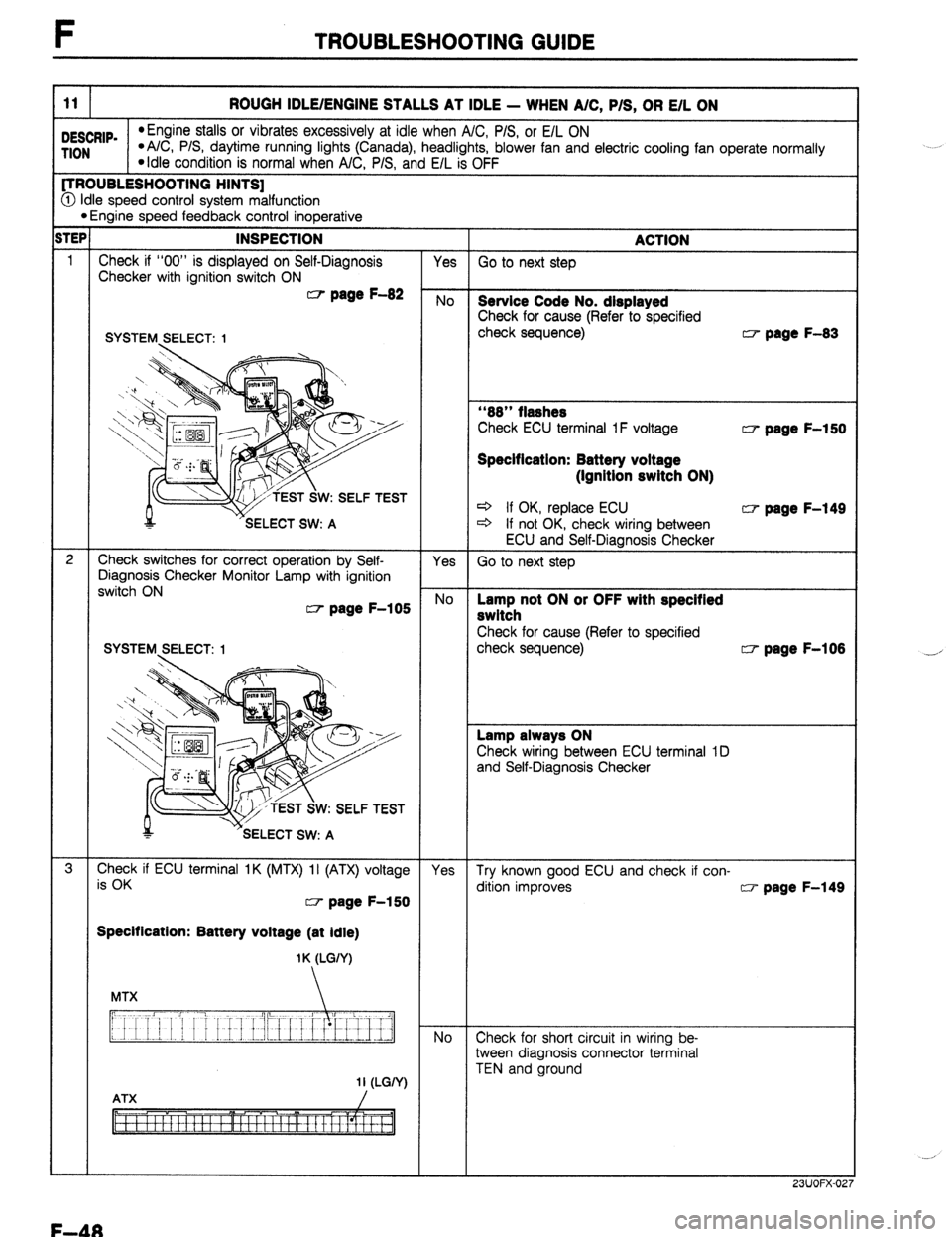
11 ROUGH IDLE/ENGINE STALLS AT IDLE - WHEN A/C, P/S, OR E/L ON
DESCRIP.
*Engine stalls or vibrates excessively at idle when A/C, P/S, or E/L ON TION *A/C, P/S, daytime running lights (Canada), headlights, blower fan and electric cooling fan operate normally
*Idle condition is normal when A/C, P/S, and E/L is OFF (TROUBLESHOOTING HINTS]
@ Idle speed control system malfunction l Engine speed feedback control inoperative ;TEP INSPECTION
ACTION
1
Check if “00” is displayed on Self-Diagnosis Yes
Checker with ignition switch ON Go to next step W page F-82 No
Service Code No. displayed
Check for cause (Refer to specified
SYSTEM SELECT: 1 check sequence) w page F-83
“88” flashes
W:SELFTEST
Check ECU terminal 1 F voltage w page F-150
Specification: Battery voltage
(Ignition switch ON)
* If OK, replace ECU w page F-149
c3 If not OK, check wiring between
ECU and Self-Diagnosis Checker
2 Check switches for correct operation by Self-
Yes
Diagnosis Checker Monitor Lamp with ignition Go to next step
switch ON CT page F-105
No Lamp not ON or OFF with specltied
switch
Check for cause (Refer to specified
check sequence) w page F-108
Lamp always ON
Check wiring between ECU terminal ID
and Self-Diagnosis Checker
W:SELFTEST
3
EhFKk if ECU terminal IK (MTX) II (ATX) voltage
Yes Try known good ECU and check if con-
dition improves w page F-150 w page F-149
Specification: Battery voltage (at Idle)
1 K (LGIY)
No
Check for short circuit in wiring be-
tween diagnosis connector terminal
TEN and ground
23UOFX-02
-’
F-48
Page 315 of 1164

TROUBLESHOOTING GUIDE F
12 ROUGH IDLE/ENGINE STALLS JUST AFTER STARTING
DESCRIP-
*Engine starts normally but vibrates excessively or stalls just after starting (acceleration from idle) TION
*Idle conditions are normal in the other conditions [TROUBLESHOOTING HINTS]
@ Fuel injection control system or idle speed control sys-
@ Idle speed misadjustment
tern malfunction @ Ignition timing misadjustment
*Start signal not input to ECU iTEl
-s-- 3
4
5 INSPECTION
-T- ACTION
Check if “00” is displayed on Self-Diagnosis
Checker with ignition switch ON w page F-82
SYSTEM,SELECT: I
r -SELECT SW: A
Check if ECU terminal voltages are OK
MTX...Especially 1 N
ATX... Especially 1T w page F-150
Connect System Selector to diagnosis connector
and set Test Switch to “SELF TEST” and check
for correct ignition timing at idle after warm-up w page F-78
Ignition timing (BTDC)
l BP DOHC : 9”-11 o l BP SOHC : 4O--6O
l B8 : 60-80
Check continuity between throttle sensor termi-
nals IDL and E CT page F-159
MTX
Clearance between throttle
lever and stopper
MTX O.lmm (0.004 in)
1 .Omm (0.039 in)
ATX 0.1 mm (0.004 in)
0.6mm (0.024 in) Continuity
Yes
No
Yes
No
Try known good ECU and check if condition
mproves w page F-149 Yes
No
Yes
Go to next step No
Check for cause Yes
In same condition as Step 3 inspection
and apply parking brake
Check for correct idle speed w page F-80
Idle speed: 700-800 rpm
No
Adjust Yes
Go to next step No
Adjust Go to next step Service Code No. displayed
Check for cause (Refer to specified
check sequence) w page F-83
“88” flashes
Check ECU terminal IF voltage w page F-150
Specification: Battery voltage
(Ignition switch ON)
d If OK, replace ECU w page F-149
* If not OK, check wiring between
ECU and Self-Diagnosis Checker c7 page F-151
3 If OK, go to next step
3 If not OK, adjust idle speed w page F-80
w page F-79
w page F-159
F-49
Page 318 of 1164
![MAZDA PROTEGE 1992 Owners Manual F TROUBLESHOOTING GUIDE
14 IDLE MOVES UP AND DOWN/IDLE HUNTING
DESCRIP-
*Engine speeds up and down periodically at idle
TION
[TROUBLESHOOTING HINTS]
@ idle switch (built in throttle sensor) OFF MAZDA PROTEGE 1992 Owners Manual F TROUBLESHOOTING GUIDE
14 IDLE MOVES UP AND DOWN/IDLE HUNTING
DESCRIP-
*Engine speeds up and down periodically at idle
TION
[TROUBLESHOOTING HINTS]
@ idle switch (built in throttle sensor) OFF](/img/28/57077/w960_57077-317.png)
F TROUBLESHOOTING GUIDE
14 IDLE MOVES UP AND DOWN/IDLE HUNTING
DESCRIP-
*Engine speeds up and down periodically at idle
TION
[TROUBLESHOOTING HINTS]
@ idle switch (built in throttle sensor) OFF at idle
@ Air leakage
@ Fuel injection amount inconstant
spoor contact point inside airflow meter
@ Poor ignition
iTEP INSPECTION
1 Check if “00” is displayed on Self-Diagnosis
Checker with ignition switch ON
CT page F-82
SYSTEM SELECT: 1
ACTION
Yes Go to next step
No
Service Code No. displayed
Check for cause (Refer to specified
check sequence) w page F-83
“88” flashes
,,;9 Check ECU terminal 1F voltage w page F-150
Specification: Battery voltage
(Ignition switch ON)
W: SELF TEST + If OK, replace ECU KIT page F-149
ELECT SW: A + If not OK, check wiring between
ECU and Self-Diagnosis Checker
2 Check for correct intake manifold vacuum at idle Yes Go to next step
Intake manifold vacuum:
More than 450 mmHg (17.7 inHg)
No Low vacuum
Check for air leakage at intake air
system
3 Check if air cleaner element is clean Yes Go to next step
w page F-79
No Replace air cleaner element
4
Disconnect high-tension lead at idle and check if Yes Go to next step
engine speed decreases equally at each cylinder
No Go to Step 9
5 Check if ECU terminal voltages are OK Yes Go to next step
w page F-150
No Check for cause KII page F-151
6
Connect System Selector to diagnosis connector Yes Go to next step
and set Test Switch to “SELF TEST” and check
for correct ignition timing at idle after warm-up
w page F-79
Ignition timing (BTDC)
l BP DOHC : 9”-11 o l BP SOHC : 4O-8” l B6 : 6O--8O No Adjust ignition timing r-7 page F-79
TEST SWITCH . .
F-52