steering wheel adjustment MAZDA PROTEGE 1992 Workshop Manual
[x] Cancel search | Manufacturer: MAZDA, Model Year: 1992, Model line: PROTEGE, Model: MAZDA PROTEGE 1992Pages: 1164, PDF Size: 81.9 MB
Page 627 of 1164

INDEX
ENGINE SPEED SENSING POWER STEERING (ESPS)
FLUID
ATF M STEERING WHEEL PLAY
O-30mm (O-l .18 in)
SPECIFICATION
-IIt or Dexron@lI
I T nFFl FCTIC-IN
--. --w. .-.. NEW: 8.0-9.0mm (0.31-0.35 in)
USED: 9.0-lO.Omm (0.35-0.39 in)
LIMIT: 11.5mm (0.45 in)
23UONX-00
1. Boot
4. Drive belt
Removal / installation
.................. page N- 6 Inspection ................................... page N-41
2. Steering gear and linkage Adjustment .................................
page N-42
Removal / Installation.. ................ page N-30 Replacement .............................. page N-42
Disassembly / Inspection.. ..........
page N-31 5. Power steering fluid
Assembly..
.................................. page N-34 Air bleeding ................................ page N-26
3. Power steering oil pump Inspection.. .................................
page N-27
Removal I Installation
.................. page N-37 6. Steering wheel and column
Disassembly / Inspection I Inspection (On-vehicle).
.............. page N-26
Assembly ..................................
page N-38 Removal / Installation..
................ page N- 9
Disassembly / Assembly ............. page
N-l 0
Inspection ................................... page N-l 1
N-3
Page 713 of 1164

WHEEL ALIGNMENT
WHEEL ALIGNMENT
PRE-INSPECTION
1. Check the tire inflations and set to the recommended pressure, if necessary.
2. Inspect the front wheel bearing play; replace the bearing if necessary.
3. inspect the wheel and tire runout.
4. Inspect the ball joints and steering linkage for any excessive looseness.
5. The vehicle must be on level ground and have no luggage or passenger load.
6. The difference in height between the left and right sides from the center of the wheel to the fender brim
must not exceed
10mm (0.39 in).
7. Shake the vehicle to check operation of the shock absorbers.
03UORX.007
FRONT WHEEL ALIGNMENT
Specifications
item
Specifications
Maximum Inner 4o” f: 2O
steering angle Outer
33O f 2O
Total mm (in) 2 f 3 (0.08 f 0.12)
toe-in dearee 0.20 f 0.30 Wheel alignment
(*‘Unladen) Front
*I Fuel tank full; radiator coolant and Camber angle -0005 * 45’
Caster angle 1°55’ f 55’
Kingpin angle 12O25’
engine oil at specified level; and spare tire, jack, and tools in designated positions.
23UORX-008
I
I 23UORX-023
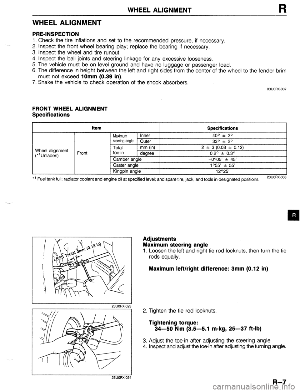
Adjustments
Maximum steering angle
1. Loosen the left and right tie rod locknuts, then turn the tie
rods equally.
Maximum left/right difference: 3mm (0.12 in)
2. Tighten the tie rod locknuts.
Tightening torque:
34-50 N-m (3.5-5.1 m-kg, 25-37 ft-lb)
3. Adjust the toe-in after adjusting the steering angle.
4. Inspect and adjust the toe-in after adjusting the turning angle.
I 23UORX-024
R-7