MERCEDES-BENZ AMG GT COUPE 2018 Owner's Manual
Manufacturer: MERCEDES-BENZ, Model Year: 2018, Model line: AMG GT COUPE, Model: MERCEDES-BENZ AMG GT COUPE 2018Pages: 294, PDF Size: 4.76 MB
Page 231 of 294
door opener, contact a Mercedes-Benz Service
Center.
Alternatively, you can call the following tele-
phone assistance services:
RUSA:Mercedes-Benz Customer Assistance
Center at 1-800 FOR-MERCEDES
RCanada: Customer Service at
1-800-387-0100
RHomeLink®hotline 1-800-355-3515 (free of
charge)
More information on HomeLink
®and/or com-
patible products is also available online at
http://www.homelink.co m.
Notes on the declaration of conformity
(
Ypage 27).
USA: FCC ID: CB2HMIHL4
Canada: IC: 279B-HMIHL4
Important safety notes
GWARNING
When you operate or program the garage door
with the integrated garage door opener, per-
sons in the range of movement of the garage
door can become trapped or struck by the
garage door. There is a risk of injury.
When using the integrated garage door
opener, always make sure that nobody is
within the range of movement of the garage
door.
GWARNING
Combustion engines emit poisonous exhaust
gases such as carbon monoxide. Inhaling
these exhaust gases leads to poisoning. There
is a risk of fatal injury. Therefore never leave
the engine running in enclosed spaces with-
out sufficient ventilation.
Programming
Programming the buttons
Pay attention to the "Important safety notes"
(Ypage 229).
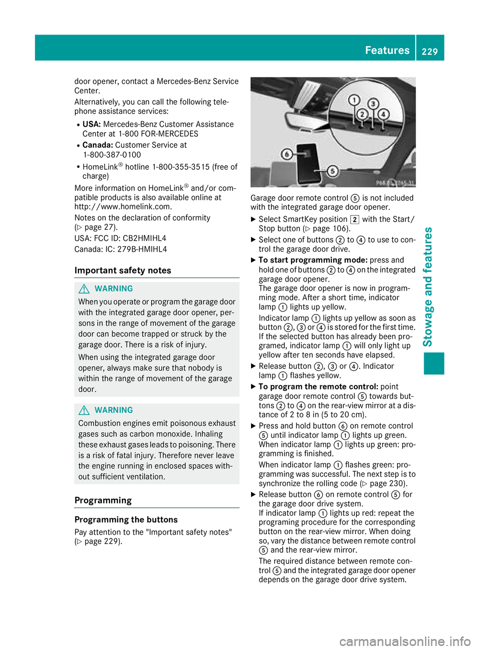
Garage door remote control Ais not included
with the integrated garage door opener.
XSelect SmartKey position 2with the Start/
Stop button (Ypage 106).
XSelect one of buttons ;to? to use to con-
trol the garage door drive.
XTo start programming mode: press and
hold one of buttons ;to? on the integrated
garage door opener.
The garage door opener is now in program-
ming mode. After a short time, indicator
lamp :lights up yellow.
Indicator lamp :lights up yellow as soon as
button ;,=or? is stored for the first time.
If the selected button has already been pro-
gramed, indicator lamp :will only light up
yellow after ten seconds have elapsed.
XRelease button ;,=or?. Indicator
lamp :flashes yellow.
XTo program the remote control: point
garage door remote control Atowards but-
tons ;to? on the rear-view mirror at a dis-
tance of 2 to 8 in (5 to 20 cm).
XPress and hold button Bon remote control
A until indicator lamp :lights up green.
When indicator lamp :lights up green: pro-
gramming is finished.
When indicator lamp :flashes green: pro-
gramming was successful. The next step is to
synchronize the rolling code (
Ypage 230).
XRelease button Bon remote control Afor
the garage door drive system.
If indicator lamp :lights up red: repeat the
programing procedure for the corresponding
button on the rear-view mirror. When doing
so, vary the distance between remote control
A and the rear-view mirror.
The required distance between remote con-
trol Aand the integrated garage door opener
depends on the garage door drive system.
Features229
Stowage and features
Z
Page 232 of 294
Several attempts might be necessary. You
should test every position for at least
25 seconds before trying another position.
Synchronizing the rolling code
Pay attention to the "Important safety notes"
(Ypage 229).
If the garage door system uses a rolling code,
you will also have to synchronize the garage
door system with the integrated garage door
opener in the rear-view mirror. To do this you will
need to use the programming button on the door
drive control panel. The programming button
may be located in different places depending on
the manufacturer. It is usually located on the
door drive unit on the garage ceiling.
Familiarize yourself with the garage door drive
operating instructions, e.g. under "Program-
ming additional remote controls", before carry-
ing out the following steps.
Your vehicle must be within reach of the garage
door or gate opener drive. Make sure that nei-
ther your vehicle nor any persons/objects are
present within the sweep of the door or gate.
XSelect SmartKey position 2with the Start/
Stop button (Ypage 106).
XGet out of the vehicle.
XPress the programming button on the door
drive unit.
You now have 30 seconds to initiate the next
step.
XGet into the vehicle.
XPress previously programed button ;,=
or ? on the integrated garage door opener
repeatedly until the door closes.
The rolling code synchronization is then com- plete.
Notes on programming the remote con-
trol
Canadian radio frequency laws require a "break"
(or interruption) of the transmission signals
after broadcasting for a few seconds. Therefore,
these signals may not last long enough for the
integrated garage door opener. The signal is notrecognized during programming. Comparable
with Canadian law, some U.S. garage door open-
ers also feature a "break". Proceed as follows:
Rif you live in Canada.
Rif you have difficulties programming the
garage door opener (regardless of where you
live) when following the programming steps.
XPress and hold one of buttons
;to? on the
integrated garage door opener.
After a short time, indicator lamp :lights up
yellow.
XRelease the button.
Indicator lamp :flashes yellow.
XPress button Bof garage door remote con-
trol Afor two seconds, then release it for two
seconds.
XPress button Bagain for two seconds.
XRepeat this sequence on button Bof remote
control Auntil indicator lamp :lights up
green.
When indicator lamp :lights up green: pro-
gramming is finished.
When indicator lamp :fl
ashes green: pro-
gramming was successful. The next step is to
synchronize the rolling code.
XRelease button Bof remote control Aof the
garage door drive.
When indicator lamp :lights up red: repeat
the programming process for the correspond-
ing button on the rear-view mirror. When
doing so, vary the distance between remote
control Aand the rear-view mirror.
The required distance between remote con-
trol Aand the integrated garage door opener
depends on the garage door drive system.
Several attempts might be necessary. You
should test every position for at least
25 seconds before trying another position.
Problems when programming
If you are experiencing problems programming
the integrated garage door opener on the rear-
view mirror, take note of the following instruc-
tions:
RCheck the transmitter frequency used by
garage door drive remote control Aand
whether it is supported. The transmitter fre-
quency can usually be found on the back of
remote control Afor the garage door drive.
The integrated garage door opener is com-
patible with devices that have units which
230Features
Stowage and features
Page 233 of 294
operate in the frequency range of 280 to
433 MHz.
RReplace the batteries in garage door remote
controlA. This increases the likelihood that
garage door remote control Awill transmit a
strong and precise signal to the integrated
garage door opener.
RWhen programming, hold remote control A
at varying distances and angles from but-
tons ;to? which you are programming. Try
various angles at a distance between 2and
8 inches (5to 20 cm) or at the same angle but
at varying distances.
RIf a further remote control Ais available for
the same garage door drive, repeat the same
programming steps with this remote control
A. Before performing these steps, make sure
that new batteries have been installed in
garage door drive remote control A.
RNote that some remote controls only transmit
for a limited amount of time (the indicator
lamp on the remote control goes out). Press
buttonBon remote control Aagain before
transmission ends.
RAlign the antenna cable of the garage door
opener unit. This can improve signal recep-
tion/transmission.
Opening/closing the garage door
After it has been programmed, the integrated
garage door opener performs the function of the
garage door system remote control. Please also
read the operating instructions for the garage
door system.
XSelect key position 2with the Start/Stop
button (Ypage 106).
XPress button ;,=or? which you pro-
grammed to operate the garage door.
Garage door system with a fixed code: indi-
cator lamp :lights up green.
Garage door system with a rolling code: indi-
cator lamp :flashes green.
The transmitter will transmit a signal as long
as the button is pressed. The transmission is
halted after a maximum of ten seconds and
indicator lamp :lights up yellow.
XPress button ;,=or? again if necessary.
Clearing the memory
Make sure that you clear the memory of the
integrated garage door opener before selling the
vehicle.
XSelect key position 2with the Start/Stop
button (Ypage 106).
XPress and hold buttons ;and ?.
Indicator lamp :initially lights up yellow and
then green.
XRelease buttons ;and ?.
The memory of the integrated garage door
opener in the rear-view mirror is cleared.
Floormats
GWARNING
Objects in the driver's footwell can restrict the pedal travel or obstruct a depressed pedal.
The operating and road safety of the vehicle is
jeopardized. There is a risk of an accident.
Make sure that all objects in the vehicle are
stowed correctly, and that they cannot enter
the driver's footwell. Install the floormats
securely and as specified in order to ensure
sufficient clearance for the pedals. Do not use
loose floormats and do not place floormats on
top of one another.
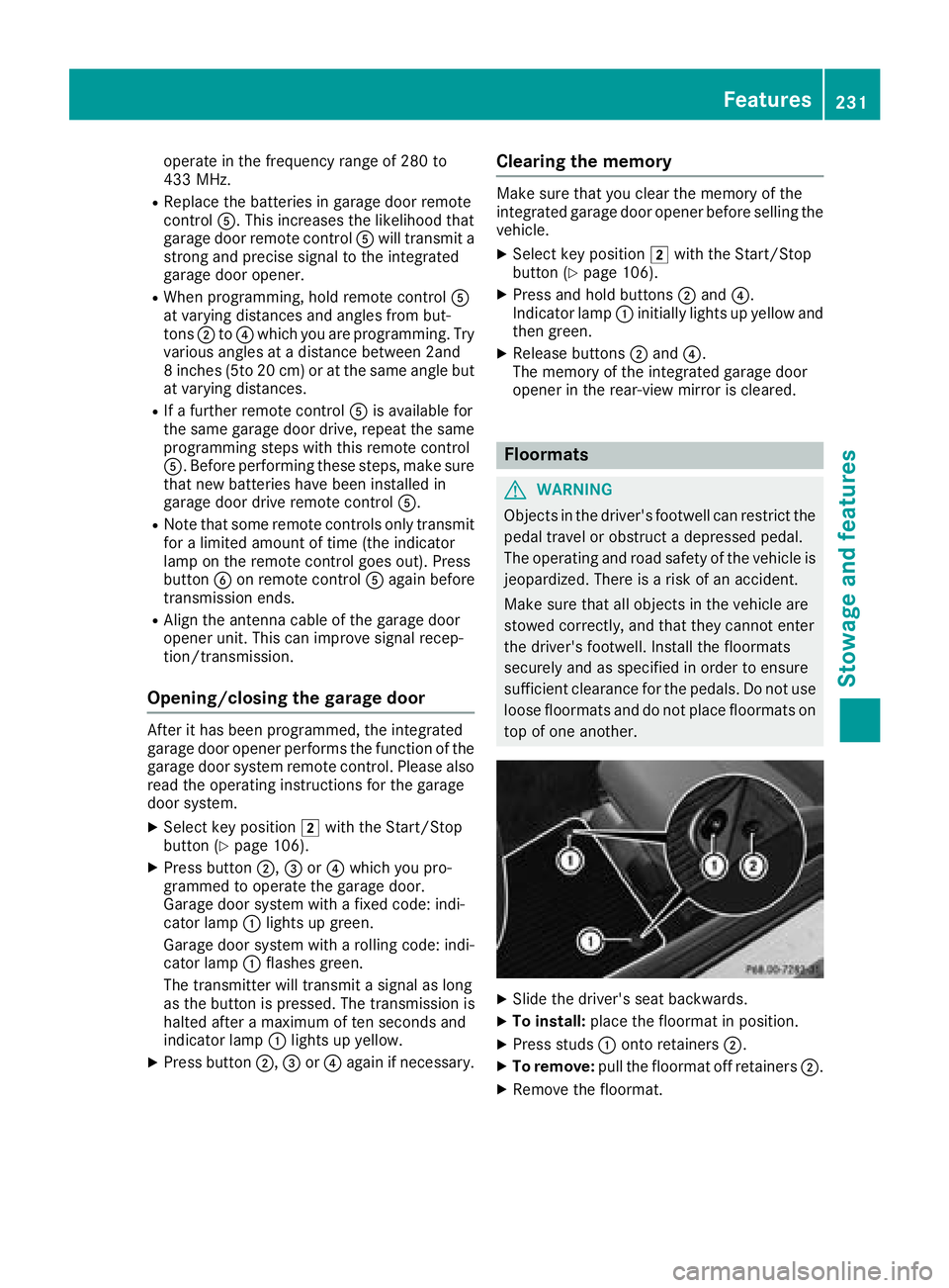
XSlide the driver's seat backwards.
XTo install: place the floormat in position.
XPress studs :onto retainers ;.
XTo remove:pull the floormat off retainers ;.
XRemove the floormat.
Features231
Stowage and features
Z
Page 234 of 294
Engine compartment
Hood
Important safety notes
GWARNING
If the hood is unlatched, it may open up when the vehicle is in motion and block your view.
There is a risk of an accident.
Never unlatch the hood while driving. Before
every trip, ensure that the hood is locked.
GWARNING
When opening and closing the hood, it may
suddenly fall into the closed position. There is a risk of injury to persons within range of
movement of the hood.
Open and close the hood only when no one is
within its range of movement.
GWARNING
Opening the hood when the engine is over-
heated or when there is a fire in the engine
compartment could expose you to hot gases
or other service products. There is a risk of
injury.
Let an overheated engine cool down before
opening the hood. If there is a fire in the
engine compartment, keep the hood closed
and contact the fire department.
GWARNING
The engine compartment contains moving
components. Certain components, such as
the radiator fan, may continue to run or start
again suddenly when the ignition is off. There is a risk of injury.
If you need to do any work inside the engine
compartment:
Rswitch off the ignition
Rnever reach into the area where there is a
risk of danger from moving components,
such as the fan rotation area
Rremove jewelry and watches
Rkeep items of clothing and hair, for exam-
ple, away from moving parts
GWARNING
The ignition system and the fuel injection sys-
tem work under high voltage. If you touch
components which are under voltage, you
could get an electric shock. There is a risk of
injury.
Never touch components of the ignition sys-
tem or fuel injection system when the ignition
is switched on.
Opening the hood
GWARNING
Certain components in the engine compart-
ment, such as the engine, radiator and parts
of the exhaust system, can become very hot.
Working in the engine compartment poses a
risk of injury.
Where possible, let the engine cool down and touch only the components described in the
following.
GWARNING
When the hood is open and the windshield
wipers are set in motion, you can be injured by
the wiper linkage. There is a risk of injury.
Always switch off the windshield wipers and
the ignition before opening the hood.
!Make sure that the windshield wipers are
not folded away from the windshield. You
could otherwise damage the windshield wip-
ers or the hood.
232Engine compartment
Maintenance and care
Page 235 of 294
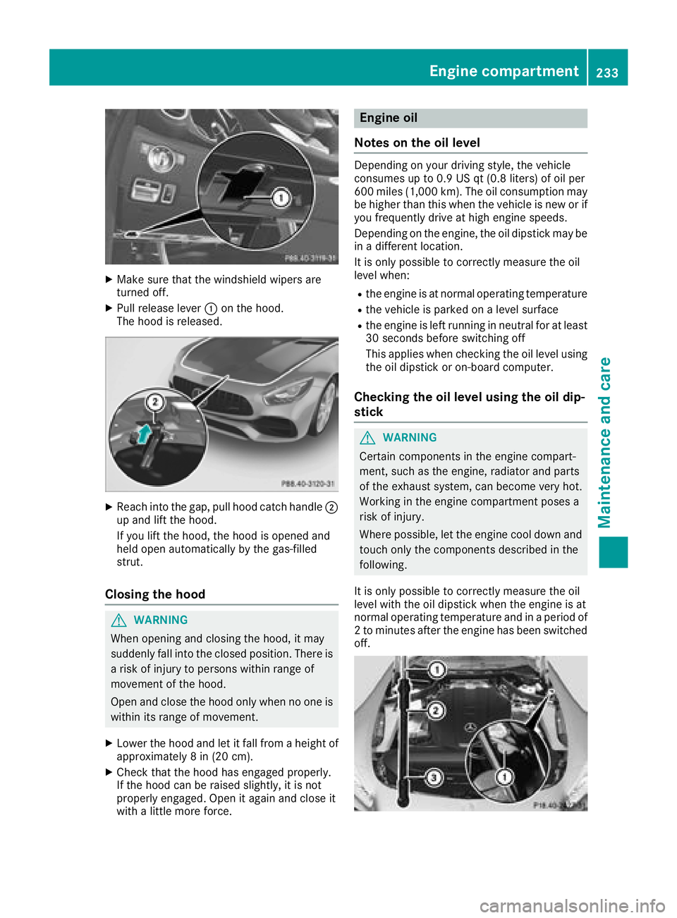
XMake sure that the windshield wipers are
turned off.
XPull release lever:on the hood.
The hood is released.
XReach into the gap, pull hood catch handle ;
up and lift the hood.
If you lift the hood, the hood is opened and
held open automatically by the gas-filled
strut.
Closing the hood
GWARNING
When opening and closing the hood, it may
suddenly fall into the closed position. There is a risk of injury to persons within range of
movement of the hood.
Open and close the hood only when no one is
within its range of movement.
XLower the hood and let it fall from a height of
approximately 8 in (20 cm).
XCheck that the hood has engaged properly.
If the hood can be raised slightly, it is not
properly engaged. Open it again and close it
with a little more force.
Engine oil
Notes on the oil level
Depending on your driving style, the vehicle
consumes up to 0.9 US qt (0.8 liters) of oil per
600 miles (1,000 km). The oil consumption may be higher than this when the vehicle is new or if
you frequently drive at high engine speeds.
Depending on the engine, the oil dipstick may be
in a different location.
It is only possible to correctly measure the oil
level when:
Rthe engine is at normal operating temperature
Rthe vehicle is parked on a level surface
Rthe engine is left running in neutral for at least
30 seconds before switching off
This applies when checking the oil level using
the oil dipstick or on-board computer.
Checking the oil level using the oil dip-
stick
GWARNING
Certain components in the engine compart-
ment, such as the engine, radiator and parts
of the exhaust system, can become very hot.
Working in the engine compartment poses a
risk of injury.
Where possible, let the engine cool down and touch only the components described in the
following.
It is only possible to correctly measure the oil
level with the oil dipstick when the engine is at
normal operating temperature and in a period of
2 to minutes after the engine has been switched
off.
Engine compartment233
Maintenance and care
Z
Page 236 of 294
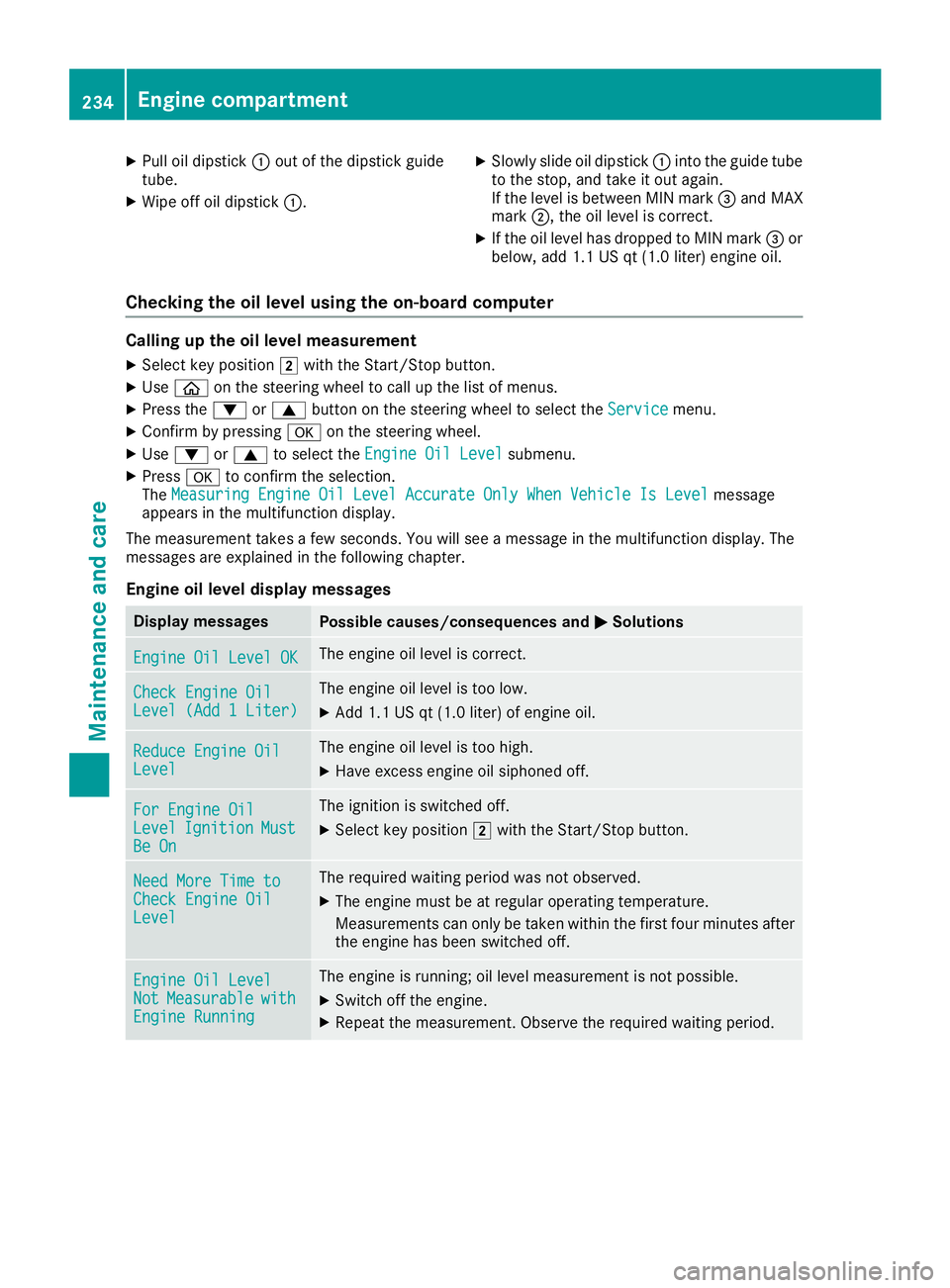
XPull oil dipstick:out of the dipstick guide
tube.
XWipe off oil dipstick :.
XSlowly slide oil dipstick :into the guide tube
to the stop, and take it out again.
If the level is between MIN mark =and MAX
mark ;, the oil level is correct.
XIf the oil level has dropped to MIN mark =or
below, add 1.1 US qt (1.0 liter) engine oil.
Checking the oil level using the on-board computer
Calling up the oil level measurement
XSelect key position 2with the Start/Stop button.
XUse ò on the steering wheel to call up the list of menus.
XPress the :or9 button on the steering wheel to select the Servicemenu.
XConfirm by pressingaon the steering wheel.
XUse: or9 to select the Engine Oil Levelsubmenu.
XPressato confirm the selection.
The Measuring Engine Oil Level Accurate Only When Vehicle Is Levelmessage
appears in the multifunction display.
The measurement takes a few seconds. You will see a message in the multifunction display. The
messages are explained in the following chapter.
Engine oil level display messages
Display messagesPossible causes/consequences and MSolutions
Engine Oil Level OKThe engine oil level is correct.
Check Engine OilLevel (Add 1 Liter)
The engine oil level is too low.
XAdd 1.1 US qt (1.0 liter) of engine oil.
Reduce Engine OilLevel
The engine oil level is too high.
XHave excess engine oil siphoned off.
For Engine OilLevelIgnitionMustBe On
The ignition is switched off.
XSelect key position2with the Start/Stop button.
Need More Time toCheck Engine OilLevel
The required waiting period was not observed.
XThe engine must be at regular operating temperature.
Measurements can only be taken within the first four minutes after
the engine has been switched off.
Engine Oil LevelNotMeasurablewithEngine Running
The engine is running; oil level measurement is not possible.
XSwitch off the engine.
XRepeat the measurement. Observe the required waiting period.
234Engine compartment
Maintenance and care
Page 237 of 294
Display messagesPossible causes/consequences andMSolutions
Engine Oil LevelCorrectMeasurementOnlyif Vehicl eIson Level Ground
The vehicl eis no tparked on alevel surface.
XPark th evehicl eon alevel surface.
Engine Oil LevelNot Measurabl e
Oil level measuremen twit hth eoil dipstick is possible. The measurin g
system is malfunctioning .
XVisitaqualified specialist workshop .
Adding engine oil
GWARNING
Certain component sin th eengin ecompart-
ment, suc has th eengine, radiato rand part s
of th eexhaust system, can become ver yhot .
Working in th eengin ecompartmen tposes a
ris kof injury.
Where possible, let th eengin ecool down and
touch only th ecomponent sdescribed in th e
following.
GWARNIN G
If engin eoil comes int ocontact wit hhot com-
ponents in th eengin ecompartment, it may
ignite. There is aris kof fir eand injury.
Mak esur ethat engin eoil is no tspilled next to
th efiller neck .Let th eengin ecool down and
thoroughly clean th eengin eoil off th ecom-
ponents before starting th eengine.
HEnvironmenta lnot e
Whe naddin goil, tak ecar eno tto spil lany. If
oil enters th esoil or waterways, it is harmful to
th eenvironment.
!Use only engin eoils and oil filters that are
approve dfor vehicles wit h aservic esystem. A
list of th eengin eoils and oil filters that hav e
been tested and approve din accordanc ewit h
Mercedes-Ben zSpecification sfor Service
Products is available at any authorize d
Mercedes-Ben zCenter. The followin
gcaus eengin efailure or damag e
to th eexhaust system:
RUse of engin eoils and oil filters that hav e
no tbeen expressl yapprove dfor th eservic e
system
RReplacement of engin eoil and oil filter after
th ereplacemen tinterval specified by th e
servic esystem has expired
RUse of engin eoil additive s
!Do notadd to omuc hoil. If th eoil level is
abov eth e"max "mar kon th edipstick ,to o
muc hoil has been added .This can lead to
damag eto th eengin eor th ecatalytic con-
verter. Hav eexcess oil siphoned off .
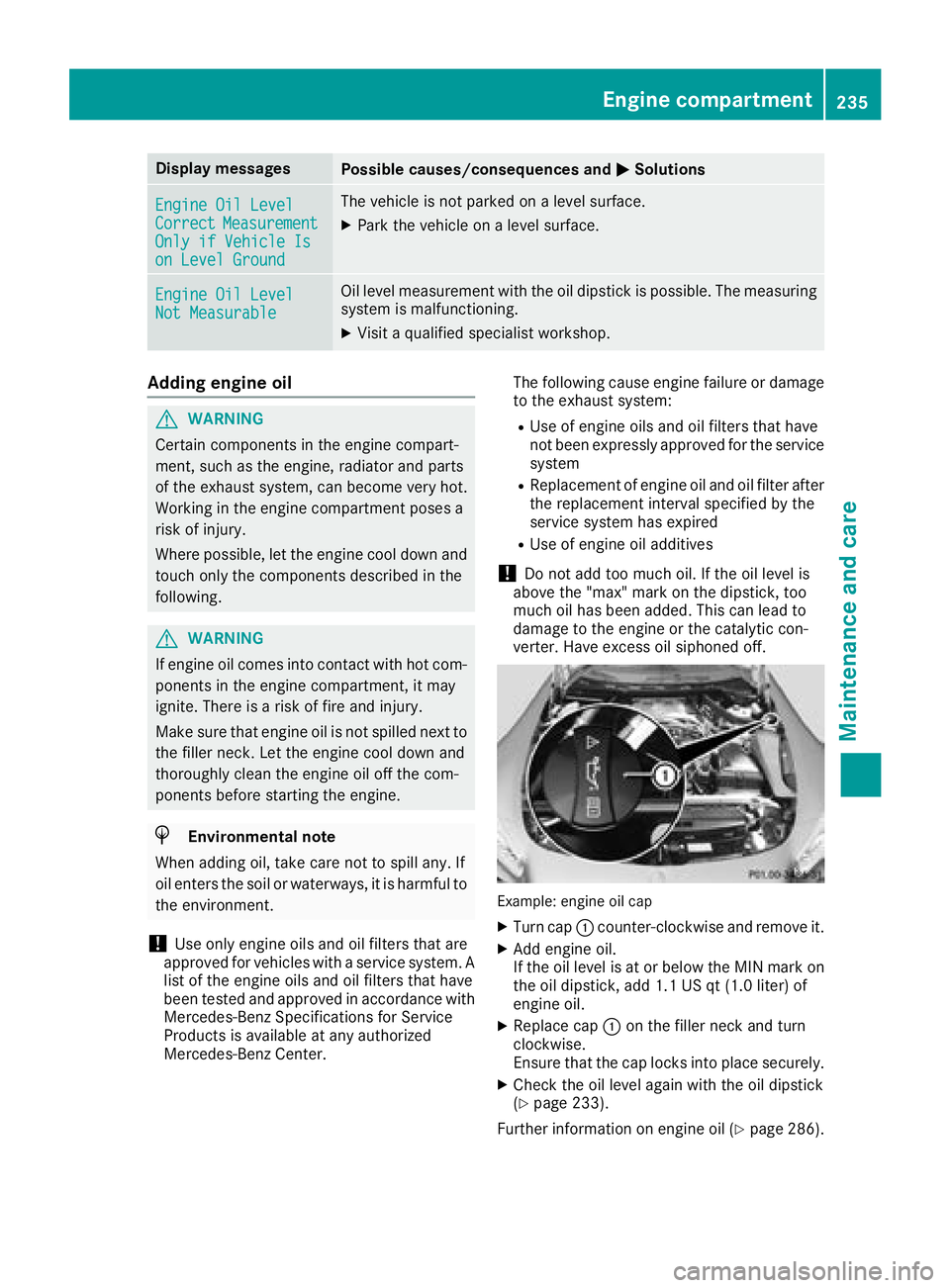
Example: engineoil cap
XTurn cap :counter-clockwise and remove it .
XAddengin eoil.
If th eoil level is at or belo wtheMIN mar kon
th eoil dipstick ,add 1. 1US qt (1. 0liter) of
engin eoil.
XReplac ecap :on th efiller neck and tur n
clockwise .
Ensur ethat th ecap locks int oplac esecurely.
XChec kth eoil level again wit hth eoil dipstick
(Ypage 233).
Further information on engin eoil (
Ypage 286).
Engine compartment235
Maintenance and care
Z
Page 238 of 294
Additional service products
Checking coolant level
GWARNIN G
Certain component sin th eengin ecompart-
ment, suc has th eengine, radiato rand part s
of th eexhaust system, can become ver yhot .
Working in th eengin ecompartmen tposes a
ris kof injury.
Wher epossible, let th eengin ecool down and
touch only th ecomponent sdescribed in th e
following.
GWARNIN G
Opening th ehoo dwhen th eengin eis over-
heated or when there is afir ein th eengin e
compartmen tcould expos eyou to hot gase s
or other servic eproducts .There is aris kof
injury.
Let an overheate dengin ecool down before
opening th ehood. If there is afir ein th e
engin ecompartment, keep th ehoo dclosed
and contact th efir edepartment.
GWARNIN G
The coolin gsystem is pressurized, particularly
when th emotor is warm .If you open th ecap ,
you could be scalded if hot coolan tsprays out .
There is aris kof injury.
Let th eengin ecool down before you open th e
cap .Wear gloves and eye protection .Slowly
open th ecap to reliev epressure.
!Befor estarting your journey, mak esur ethat
all engin ecover sare installed. Otherwise ,th e
engin ecan be damaged, e.g. throug hover-
heating .
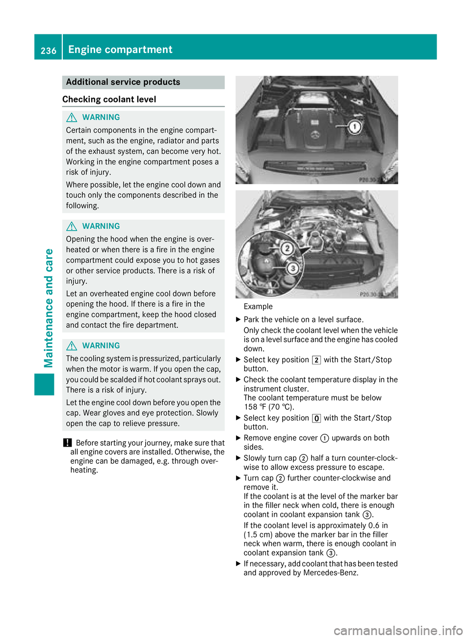
Example
XPark thevehicl eon alevel surface.
Only chec kth ecoolan tlevel when th evehicl e
is on alevel surfac eand th eengin ehas cooled
down .
XSelec tke yposition 2withth eStart/Sto p
button.
XChec kth ecoolan ttemperature display in th e
instrumen tcluster.
The coolan ttemperature mus tbe belo w
15 8 ‡ (70 †).
XSelec tke yposition uwithth eStart/Sto p
button.
XRemove engin ecover :upwards on bot h
sides.
XSlowly tur ncap ;half atur ncounter-clock -
wise to allow excess pressur eto escape.
XTurn cap ;further counter-clockwise and
remove it .
If th ecoolan tis at th elevel of th emarke rbar
in th efiller neck when cold, there is enough
coolan tin coolan texpansion tan k=.
If th ecoolan tlevel is approximately 0. 6in
(1. 5cm) abov eth emarke rbar in th efiller
neck when warm ,there is enough coolan tin
coolan texpansion tan k=.
XIf necessary, add coolan tthat has been tested
and approve dby Mercedes-Benz .
236Engine compartment
Maintenance and care
Page 239 of 294
XReplacecap ;and tur nit clockwise as far as
it will go.
XReplac eengin ecover :.
Fo rfurther information on coolant, see
(
Ypage 287).
Windshield washer system
GWARNIN G
Certain component sin th eengin ecompart-
ment, suc has th eengine, radiato rand part s
of th eexhaust system, can become ver yhot .
Workin gin th eengin ecompartmen tposes a
ris kof injury.
Wher epossible, let th eengin ecool down and
touch only th ecomponent sdescribe din th e
following.
GWARNIN G
Windshield washe rconcentrate could ignit eif
it comes int ocontact wit hhot engin ecompo -
nent sor th eexhaust system. There is aris kof
fir eand injury.
Mak esur ethat no windshield washe rcon-
centrat eis spilled next to th efiller neck .
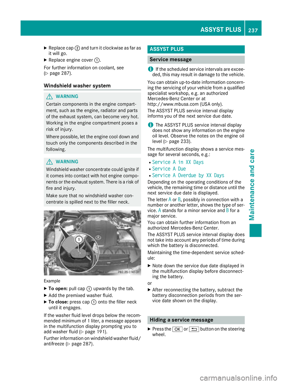
Example
XTo open :pull cap :upwards by th etab .
XAddth epremixed washe rfluid .
XTo close: press cap :onto th efiller neck
until it engages.
If th ewashe rfluid level drops belo wtherecom-
mended minimum of 1liter, amessage appear s
in th emultifunction display prompting you to
add washe rfluid (
Ypage 191).
Further information on windshield washe rfluid /
antifreez e (
Ypage 287).
ASSYST PLUS
Service message
i
If th escheduled servic eintervals are excee-
ded, this may result in damag eto th evehicle.
You can obtain up-to-date information concern -
ing th eservicing of your vehicl efrom aqualified
specialist workshop, e.g. an authorize d
Mercedes-Benz Cente ror at
http://www.mbusa.co m(US Aonly).
The ASSYS TPLU Sservic einterval display
inform syou of th enext servic edue date.
iThe ASSYS TPLU Sservic einterval display
does no tsho wany information on th eengin e
oil level. Observ eth enote son th eengin eoil
level (
Ypage 233).
The multifunction display shows aservic emes -
sage for several seconds, e.g. :
RService Ain XX Day s
RService ADue
RServic e AOverdu eby XX Day s
Dependingon th eoperating condition sof th e
vehicle, th eremaining time or distanc euntil th e
next servic edue dat eis displayed.
The lette rA
or B,possibl yin connection wit h a
number or another letter, shows th etyp eof ser -
vice. A
stand sfor aminor servic eand Bfora
major service.
You can obtain further information from an
authorize dMercedes-Benz Center.
The ASSYS TPLU Sservic einterval display does
no ttak eint oaccoun tany periods of time during
whic hth ebattery is disconnected.
Maintainin gth etime-dependen tservic esched-
ule:
XNot edown th eservic edue dat edisplayed in
th emultifunction display before disconnect -
ing th ebattery.
or
XAfte rreconnecting th ebattery, subtrac tth e
battery disconnection periods from th eser -
vic edat eshown on th edisplay.
Hiding a service message
XPress th ea or% buttonon th esteering
wheel.
ASSYST PLUS237
Maintenance and care
Z
Page 240 of 294
Displaying service messages
XSwitchon th eignition .
XUseò on thesteerin gwhee lto cal lup th e
list of menus.
XPress 9or: on thesteerin gwhee lto
selec tth eServic emenuand confirm wit h
a.
XPress 9or: on thesteerin gwhee lto
selec tth eASSYST PLU Ssubmenuand con-
fir m wit ha.
The servic edue dat eappears in th emulti-
function display.
Information about Service
Resetting th eASSYS TPLUS service
interva ldisplay
!If th eASSYST PLU Sservic einterval display
has bee ninadvertentl yreset ,this setting can
be correcte dat aqualified specialis twork-
shop.
Hav eservic ewor kcarrie dout as described in
th eMaintenance Booklet .Thi smay otherwise
lead to increase dwear and damage to th e
major assemblies or th evehicle.
A qualified specialis tworkshop ,e.g. an author -
ized Mercedes-Ben zCenter, will reset th e
ASSYST PLU Sservic einterval display after th e
servic ewor khas bee ncarrie dout .You can also
obtain further information on maintenance
work, fo rexample.
Specia lservice requirement s
The specifiedmaintenance interval take sonly
th enormal operation of th evehicle into
account. Under arduous operatin gcondition sor
increase dload on th evehicle, maintenance
wor kmus tbe carrie dout more frequently, fo r
example:
RRegular city drivin gwit hfrequent intermedi-
at estops
RIf th evehicle is primarily used to trave lshort
distances
RUse in mountainous terrain or on poo rroad
surfaces
RIf th eengin eis ofte nlef tidling fo rlon gperiods
RIn racetrac kmode Under these or similar conditions, have, fo
r
example, th eair filter, engin eoil and oil filte r
replaced or changed more frequently. Under
arduous operatin gconditions, th etires mus tbe
checke dmore often. Further information can be
obtained at aqualified specialis tworkshop ,e.g.
an authorized Mercedes-Ben zCenter.
iIn racetrac kmode, th evehicle is subjec tto
higher loads, meaning that additional main -
tenance wor kis required. If you plan race-
track use, consult aqualified specialis twork-
sho pfirst .Mercedes-Ben zrecommends that
you use an authorized Mercedes-Ben zCente r
fo rthis purpose.
Drivin gabroad
An extensive Mercedes-Ben zServic enetwor kis
also available in other countries. You can obtain
further information from any authorized
Mercedes-Ben zCenter.
Car e
General notes
HEnvironmental not e
Dispose of empty packagin gand cleanin g
cloths in an environmentally responsible man -
ner.
!Whe ncleanin gyour car ,do no tuse:
Rdry, coars eor har dcloths
Rabrasiv ecleanin gagents
Rsolvents
Rcleanin gagents containin gsolvents
Do no tscrub .
Do no ttouch th esurfaces and films wit hhar d
objects ,e.g. rings or ic escrapers .Otherwise ,
you may scratch or damage th esurfaces and
films .
!Do no tpar kyour vehicle fo r alon gperiod of
time directl yafter cleaning, particularly after
cleanin gth ewhee lrim wit hwhee lcleaner.
Wheel cleaner can lead to th eincrease dcor-
rosio nof th ebrake discs and pads .Therefore,
drive fo r afew minutes after cleaning. By
heatin gup th ebrakes, th ebrake discs and
pads dry. The vehicle can then be parke dfo r a
lon gperiod of time.
238Care
Maintenance and care