MERCEDES-BENZ C-CLASS CABRIOLET 2016 Owners Manual
Manufacturer: MERCEDES-BENZ, Model Year: 2016, Model line: C-CLASS CABRIOLET, Model: MERCEDES-BENZ C-CLASS CABRIOLET 2016Pages: 377, PDF Size: 6.9 MB
Page 221 of 377
Important safety notes
G
WARNING
The bicycle rack can detach from the vehicle if
you
R exceed the permissible payload of the
trailer tow hitch
R use the bicycle rack incorrectly
R attach the bicycle rack to the ball coupling
beneath the ball head
There is a risk of an accident.
For your safety and that of other road users,
observe the following:
R Always observe the permissible payload of
the trailer tow hitch.
R Use the bicycle rack only to transport bicy-
cles.
R Always attach the bicycle rack correctly by
clamping onto the ball head and, if possible, to the guide pin on the ball coupling as well.
R To transport four bicycles, always use bicy-
cle racks with additional support on the ball
coupling's guide pin. R
Use only bicycle racks approved by
Mercedes-Benz.
R Always comply with the bicycle rack's oper-
ating manual.
! Using unsuitable bicycle racks or using
them incorrectly can cause damage to and
fractures in the trailer tow hitch.
Use only bicycle racks approved by
Mercedes-Benz.
Bicycle racks cause your vehicle's driving char-
acteristics to change. The vehicle
R is heavier
R is restricted in its acceleration and gradient-
climbing capability
R has an increased braking distance
This can impair the vehicle's handling charac-
teristics. Adapt your driving style accordingly.
Maintain a safe distance and drive carefully.
When using bicycle racks, set the tyre pressure on the rear axle of the vehicle for the maximum
load. Further information on tyre pressure can
be found on the tyre pressure table
(Y page 345). Loading instructions
The greater the distance between the load's centre of gravity and the ball head, the higher the load exerted on the trailer tow hitch.
Therefore, observe the following notes:
R Attach heavy bicycles as close as possible to the vehicle.
R Always distribute the load on the bicycle rack as symmetrically as possible to the vehicle longi-
tudinal axis.
Before loading the bicycle rack, Mercedes-Benz advises you to remove all add-on parts from the
bicycles, e.g. bicycle baskets, child seats or batteries. This will allow you to improve the aerody-
namic resistance and the bicycle rack's centre of gravity.
Always secure bicycles against slipping and check that they are firmly seated at regular intervals.
Do not use tarpaulins or other covers. This could impair the driving characteristics and rear visibility. The aerodynamic resistance would also rise, and so would the load exerted on the trailer tow hitchas a result. 218
Bicycle rackDriving and pa
rking
Page 222 of 377
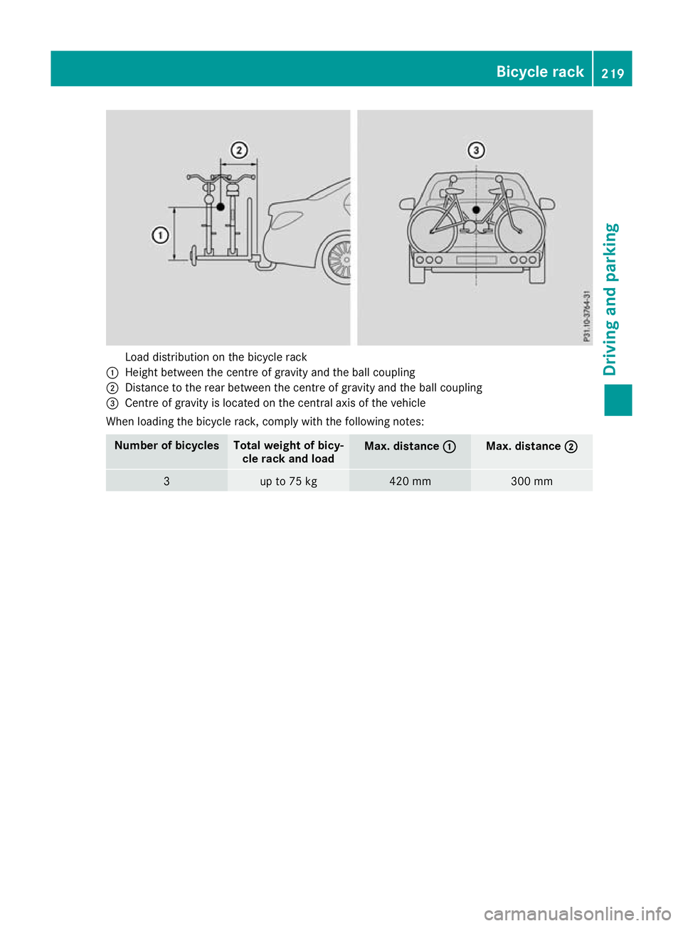
Load distribution on the bicycle rack
: Height between the centre of gravity and the ball coupling
; Distance to the rear between the centre of gravity and the ball coupling
= Centre of gravity is located on the central axis of the vehicle
When loading the bicycle rack, comply with the following notes: Number of bicycles Total weight of bicy-
cle rack and load Max. distance
:
: Max. distance
;
; 3 up to 75 kg 420 mm 300 mmBicycle rack
219Driving and parking Z
Page 223 of 377
Important safety notes
G
WARNING
Operating the integrated information systems and communications equipment in the vehicle
while driving will distract you from traffic con-
ditions. You could then lose control of the
vehicle. There is a risk of an accident.
Only operate these devices if road traffic con-
ditions permit. If you are unsure about the
surrounding conditions, pull over to a safe
location and make entries only while the vehi-
cle is stationary.
You must observe the legal requirements for the country in which you are currently driving whenoperating the on-board computer. G
WARNING
If the instrument cluster has failed or mal-
functioned, you may not recognise function
restrictions relevant to safety. The operating
safety of your vehicle may be impaired. There is a risk of an accident.
Drive on carefully. Have the vehicle checked
at a qualified specialist workshop immedi-
ately.
If the operating safety of your vehicle is
impaired, park the vehicle safely as soon as pos- sible. Contact a qualified specialist workshop.
The on-board computer shows only display mes- sages or warnings from certain systems on the
multifunction display. You should therefore
make sure your vehicle is operating safely at all times.
For an overview, see the instrument cluster illus-
tration (Y page 35). Displays and operation
Instrument cluster lighting
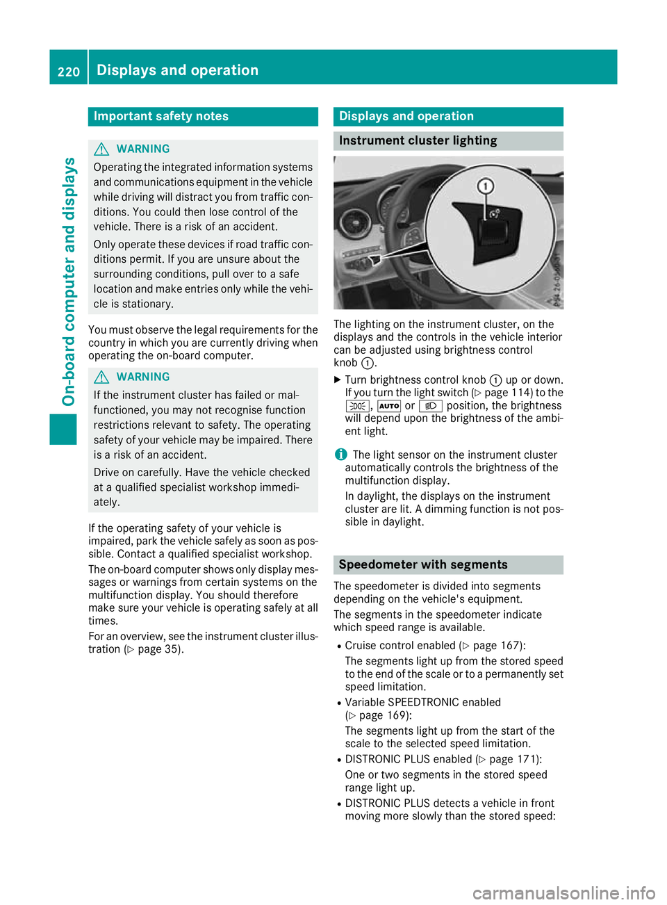
The lighting on the instrument cluster, on the
displays and the controls in the vehicle interior
can be adjusted using brightness control
knob :.
X Turn brightness control knob :up or down.
If you turn the light switch (Y page 114) to the
T, ÃorL position, the brightness
will depend upon the brightness of the ambi-
ent light.
i The light sensor on the instrument cluster
automatically controls the brightness of the
multifunction display.
In daylight, the displays on the instrument
cluster are lit. A dimming function is not pos-
sible in daylight. Speedometer with segments
The speedometer is divided into segments
depending on the vehicle's equipment.
The segments in the speedometer indicate
which speed range is available.
R Cruise control enabled (Y page 167):
The segments light up from the stored speed to the end of the scale or to a permanently set
speed limitation.
R Variable SPEEDTRONIC enabled
(Y page 169):
The segments light up from the start of the
scale to the selected speed limitation.
R DISTRONIC PLUS enabled (Y page 171):
One or two segments in the stored speed
range light up.
R DISTRONIC PLUS detects a vehicle in front
moving more slowly than the stored speed: 220
Displays and operationOn-board computer and displays
Page 224 of 377
The segments between the speed of the vehi-
cle in front and the stored speed light up. Rev counter
! Do not drive in the overrevving range. Doing
so will damage the engine.
The red band in the rev counter indicates the
engine's overrevving range.
The fuel supply is interrupted to protect the
engine when the red band is reached. Outside temperature display
You should pay special attention to road condi-
tions when temperatures are around freezing
point.
Bear in mind that the outside temperature dis-
play indicates the measured air temperature
and not the road surface temperature.
The outside temperature display is in the multi-
function display (Y page 222).
Changes in the outside temperature are dis-
played after a short delay. Coolant temperature gauge
G
WARNING
If you open the bonnet while the engine is
overheating or while there is a fire in the
engine compartment, you could come into
contact with hot gases or other leaking ser-
vice products. There is a danger of injury.
Allow an overheating engine to cool down
before opening the bonnet. If there is a fire in the engine compartment, leave the bonnet
closed and notify the fire brigade.
The coolant temperature display is shown in the lower section of the rev counter (Y page 35).
At high outside temperatures and when driving
in mountainous terrain, the coolant temperature
may rise to the end of the scale.
Under normal operating conditions and with the specified coolant level, the display may rise to
120 †. Operating the on-board computer
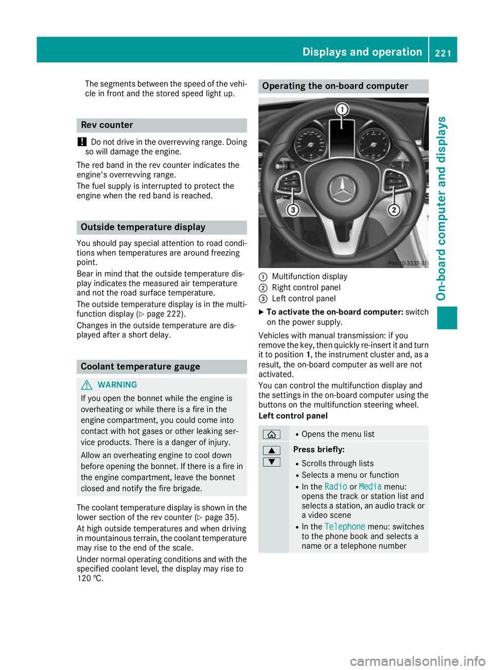
:
Multifunction display
; Right control panel
= Left control panel
X To activate the on-board computer: switch
on the power supply.
Vehicles with manual transmission: if you
remove the key, then quickly re-insert it and turn
it to position 1, the instrument cluster and, as a
result, the on-board computer as well are not
activated.
You can control the multifunction display and
the settings in the on-board computer using the buttons on the multifunction steering wheel.
Left control panel ò R
Opens the menu list 9
: Press briefly:
R Scrolls through lists
R Selects a menu or function
R In the Radio Radio orMedia
Media menu:
opens the track or station list and
selects a station, an audio track or a video scene
R In the Telephone Telephone menu: switches
to the phone book and selects a
name or a telephone number Displays and operation
221On-board computer and displays Z
Page 225 of 377
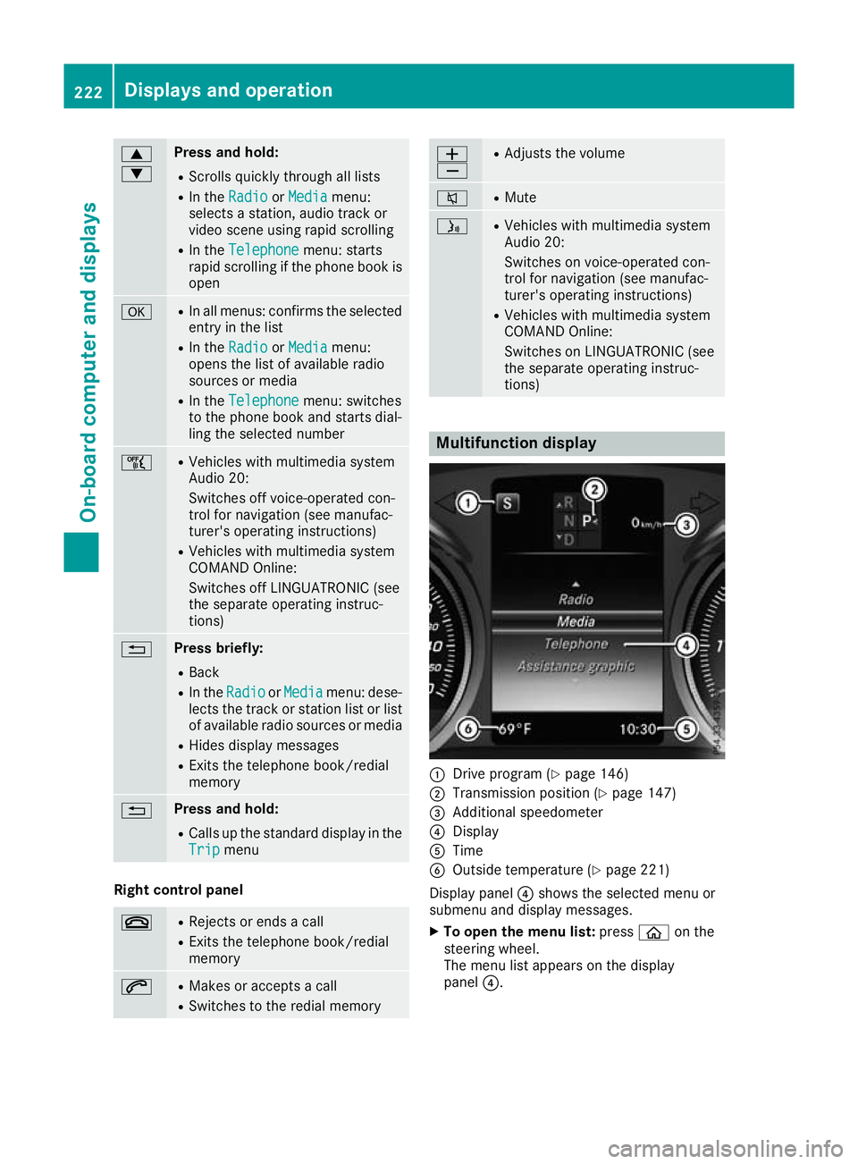
9
: Press and hold:
R
Scrolls quickly through all lists
R In the Radio Radio orMedia Media menu:
selects a station, audio track or
video scene using rapid scrolling
R In the Telephone Telephone menu: starts
rapid scrolling if the phone book is open a R
In all menus: confirms the selected
entry in the list
R In the Radio
Radio orMedia
Media menu:
opens the list of available radio
sources or media
R In the Telephone Telephone menu: switches
to the phone book and starts dial-
ling the selected number ñ R
Vehicles with multimedia system
Audio 20:
Switches off voice-operated con-
trol for navigation (see manufac-
turer's operating instructions)
R Vehicles with multimedia system
COMAND Online:
Switches off LINGUATRONIC (see
the separate operating instruc-
tions) % Press briefly:
R Back
R In the Radio Radio orMedia
Media menu: dese-
lects the track or station list or list
of available radio sources or media
R Hides display messages
R Exits the telephone book/redial
memory % Press and hold:
R
Calls up the standard display in the
Trip Trip menu Right control panel
~ R
Rejects or ends a call
R Exits the telephone book/redial
memory 6 R
Makes or accepts a call
R Switches to the redial memory W
X R
Adjusts the volume 8 R
Mute ó R
Vehicles with multimedia system
Audio 20:
Switches on voice-operated con-
trol for navigation (see manufac-
turer's operating instructions)
R Vehicles with multimedia system
COMAND Online:
Switches on LINGUATRONIC (see
the separate operating instruc-
tions) Multifunction display
:
Drive program (Y page 146)
; Transmission position (Y page 147)
= Additional speedometer
? Display
A Time
B Outside temperature (Y page 221)
Display panel ?shows the selected menu or
submenu and display messages.
X To open the menu list: pressòon the
steering wheel.
The menu list appears on the display
panel ?. 222
Displays and operationOn-board computer and displays
Page 226 of 377
Possible readings on the multifunction dis-
play:
R ZGearshift recommendation for manual
transmission (Y page 144) or for automatic
transmission (manual gearshifting)
(Y page 152)
R j Active Parking Assist (Y page 188)
R È SPEEDTRONIC (Y page 169)
R ¯ Cruise control (Y page 167)
R a DISTRONIC PLUS Steering Assist and
Stop&Go Pilot (Y page 178)
R _ Adaptive Highbeam Assist Plus
(Y page 117)
R è ECO start/stop function (Y page 137)
R ë HOLD function (Y page 179)
R ð Maximum permissible speed exceeded
(for certain countries only) Head-up display
General notes The Head-up Display projects information from
the navigation system and the driver assistance
systems above the dashboard into the driver's
field of vision. This way, the Head-up Display
enables drivers to see information without hav-
ing to take their eyes off the road.
A requirement for the display of the content is
that the following functions are available in the
vehicle and are switched on:
R Cruise control
R SPEEDTRONIC
R DISTRONIC PLUS
R Traffic Sign Assist
R Navigation
Important safety notes The head-up display is only an aid and is not a
substitute for attentive driving.
Speed limits and overtaking restrictions are not
always correctly displayed. Traffic signs always
have priority over the Traffic Sign Assist display.
The visibility of the head-up display is influenced by the following conditions:
R the driver's seat position
R the positioning of the display image
R the general light conditions R
sunglasses with polarisation filters
R wet road surfaces
R blocking of sunlight by objects on the display
cover
In the event of extreme sunlight, sections of the
display may fade. This can be reversed by
switching the head-up display off and on again.
i Vehicles with the head-up display are equip-
ped with a special windscreen. Should repairs
be necessary, have the windscreen replaced
at a qualified specialist workshop.
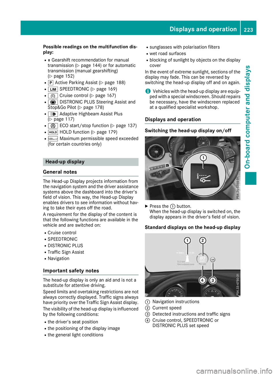
Displays and operation Switching the head-up display on/off
X
Press the :button.
When the head-up display is switched on, the display appears in the driver's field of vision.
Standard displays on the head-up display :
Navigation instructions
; Current speed
= Detected instructions and traffic signs
? Cruise control, SPEEDTRONIC or
DISTRONIC PLUS set speed Displays and operation
223On-board computer and displays Z
Page 227 of 377

AMG displays on the head-up display
:
Upshift indicator
; RACETIMER lap
= RACETIMER lap time
? Current speed
A Currently selected gear, gearshift options
with manual gearshifting
B Current engine speed
Setting options You can make the following settings on the
head-up display submenu:
R Adjust the position of the head-up display on
the windscreen (Y page 235)
R Adjust the brightness of the displays on the
head-up display (Y page 235)
R Select which information you want to appear
on the head-up display (Y page 234)
Using the Display content
Display content function, you
can, depending on your vehicle's equipment,
choose between four standard displays. The
selected content then appears on the head-
up display.
In Mercedes-AMG vehicles, you can choose
between further AMG displays in addition to
the standard displays, depending on your
vehicle's equipment.
If you select a display with traffic signs, traffic
signs detected by Traffic Sign Assist appear
on the head-up display. Menus and submenus
Menu overview
Press òon the steering wheel to open the
menu list.
Operating the on-board computer (Y page 221).Depending on the vehicle equipment, you can
select the following menus:
R Trip
Trip menu (Y page 224)
R Navi Navi menu (navigation instructions)
(Y page 226)
R Radio
Radio menu (Y page 228)
R Media
Media menu (Y page 228)
R Telephone
Telephone menu (Ypage 230)
R Assistance graphic
Assistance graphic menu (Ypage 231)
R Service
Service menu (Ypage 232)
R Settings
Settings menu (Ypage 232)
R AMG
AMG menu in Mercedes-AMG vehicles
(Y page 237) Trip menu
Standard display X
Press and hold the %button on the steer-
ing wheel until the Trip
Tripmenu with trip
meter :and total distance recorder ;
appears. 224
Menus and submenusOn-board computer and displays
Page 228 of 377
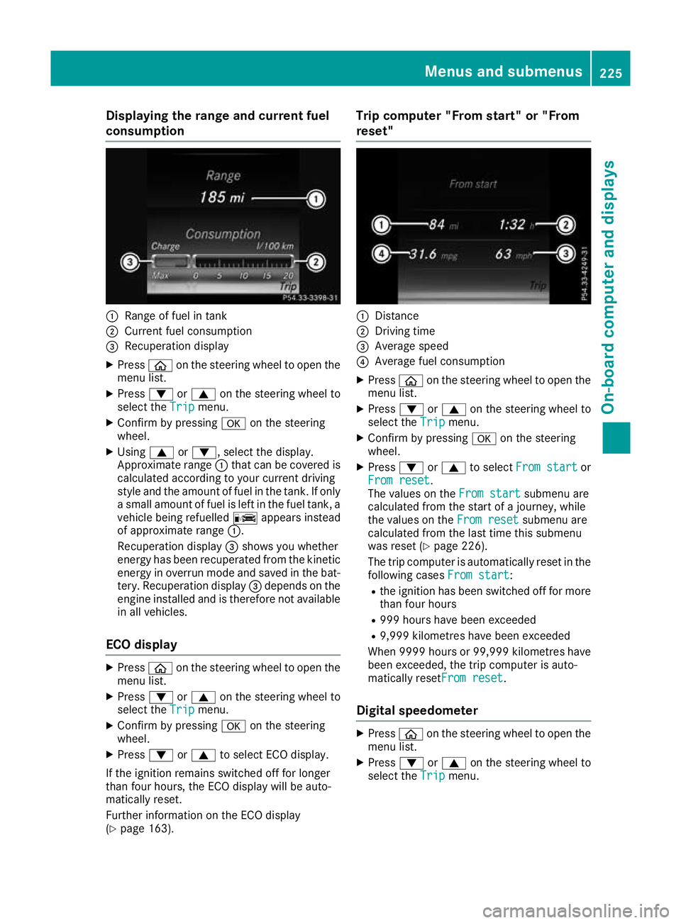
Displaying the range and current fuel
consumption :
Range of fuel in tank
; Current fuel consumption
= Recuperation display
X Press òon the steering wheel to open the
menu list.
X Press :or9 on the steering wheel to
select the Trip
Tripmenu.
X Confirm by pressing aon the steering
wheel.
X Using 9or:, select the display.
Approximate range :that can be covered is
calculated according to your current driving
style and the amount of fuel in the tank. If only a small amount of fuel is left in the fuel tank, a
vehicle being refuelled Cappears instead
of approximate range :.
Recuperation display =shows you whether
energy has been recuperated from the kinetic energy in overrun mode and saved in the bat-
tery. Recuperation display =depends on the
engine installed and is therefore not available in all vehicles.
ECO display X
Press òon the steering wheel to open the
menu list.
X Press :or9 on the steering wheel to
select the Trip
Trip menu.
X Confirm by pressing aon the steering
wheel.
X Press :or9 to select ECO display.
If the ignition remains switched off for longer
than four hours, the ECO display will be auto-
matically reset.
Further information on the ECO display
(Y page 163). Trip computer "From start" or "From
reset"
:
Distance
; Driving time
= Average speed
? Average fuel consumption
X Press òon the steering wheel to open the
menu list.
X Press :or9 on the steering wheel to
select the Trip
Trip menu.
X Confirm by pressing aon the steering
wheel.
X Press :or9 to select From start From start or
From reset
From reset.
The values on the From start From startsubmenu are
calculated from the start of a journey, while
the values on the From reset From resetsubmenu are
calculated from the last time this submenu
was reset (Y page 226).
The trip computer is automatically reset in the following cases From start
From start:
R the ignition has been switched off for more
than four hours
R 999 hours have been exceeded
R 9,999 kilometres have been exceeded
When 9999 hour sor 99,999 kilometres have
been exceeded, the trip computer is auto-
matically resetFrom reset From reset.
Digital speedometer X
Press òon the steering wheel to open the
menu list.
X Press :or9 on the steering wheel to
select the Trip
Tripmenu. Menus and submenus
225On-board computer and displays Z
Page 229 of 377
X
Confirm by pressing aon the steering
wheel.
X Press :or9 to select the digital
speedometer.
Resetting values X
Press òon the steering wheel to open the
menu list.
X Press :or9 on the steering wheel to
select the Trip
Trip menu.
X Confirm by pressing aon the steering
wheel.
X Press :or9 to select the function that
you wish to reset.
X Press abriefly.
X Press :to select Yes Yesand press ato
confirm.
You can reset the values of the following func- tions:
R Trip meter
R "From start" trip computer
R "From reset" trip computer
R ECO display
If you reset the values in the "ECO display",
the values in the "From start" trip computer
are also reset. If you reset the values in the
"From start" trip computer, the values in the
"ECO display" are also reset. Navigation menu
Displaying navigation instructions On the
Navi Navimenu, the multifunction display
shows navigation instructions. You can find fur-
ther information on navigation instructions in
the Digital Owner's Manual in the multimedia
system.
X Switch on the multimedia system.
X Press òon the steering wheel to open the
menu list.
X Press :or9 on the steering wheel to
select the Navi
Navi menu.
X Confirm by pressing aon the steering
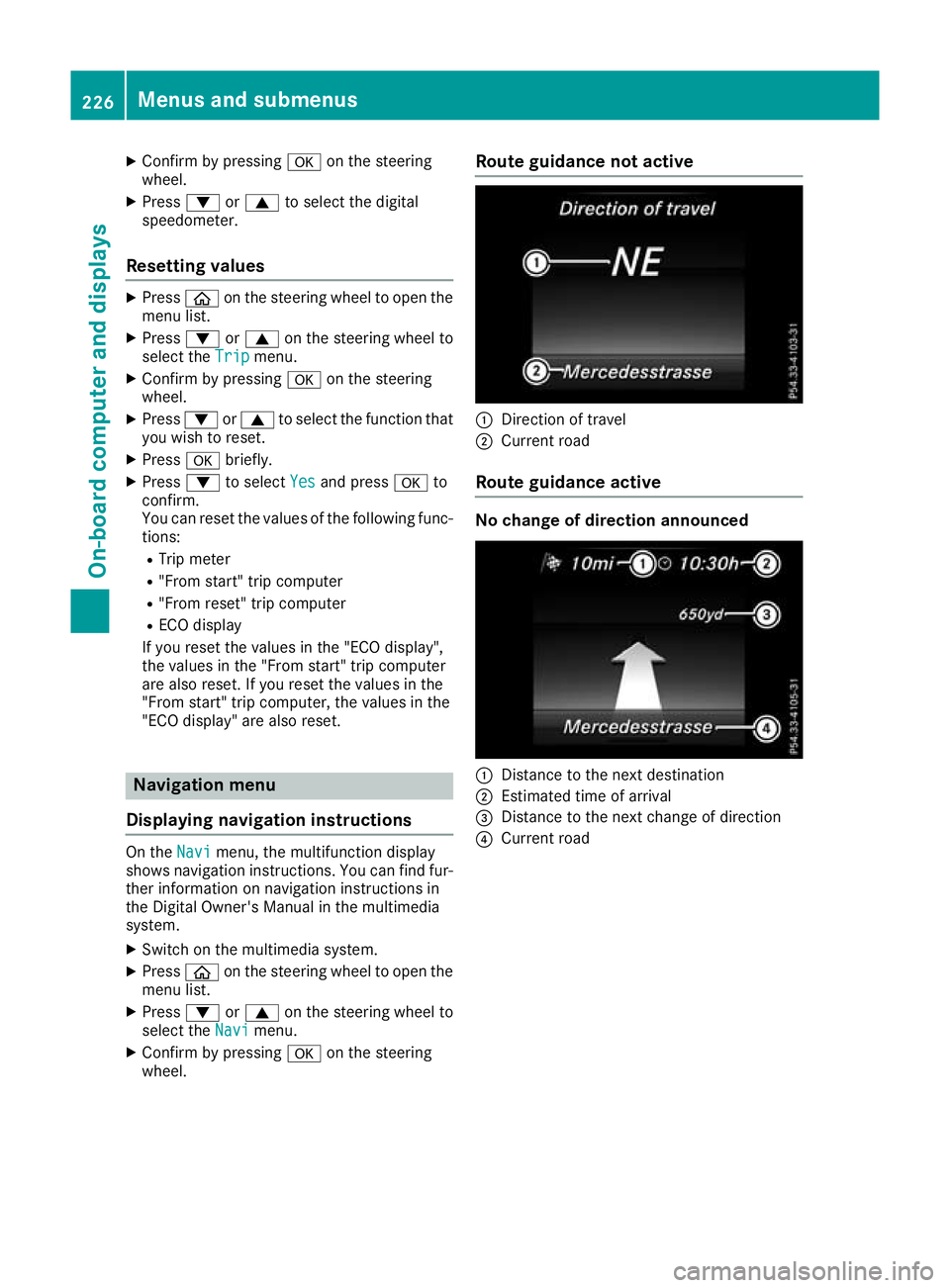
wheel. Route guidance not active
:
Direction of travel
; Current road
Route guidance active No change of direction announced
:
Distance to the next destination
; Estimated time of arrival
= Distance to the next change of direction
? Current road 226
Menus and submenusOn-board computer and displays
Page 230 of 377
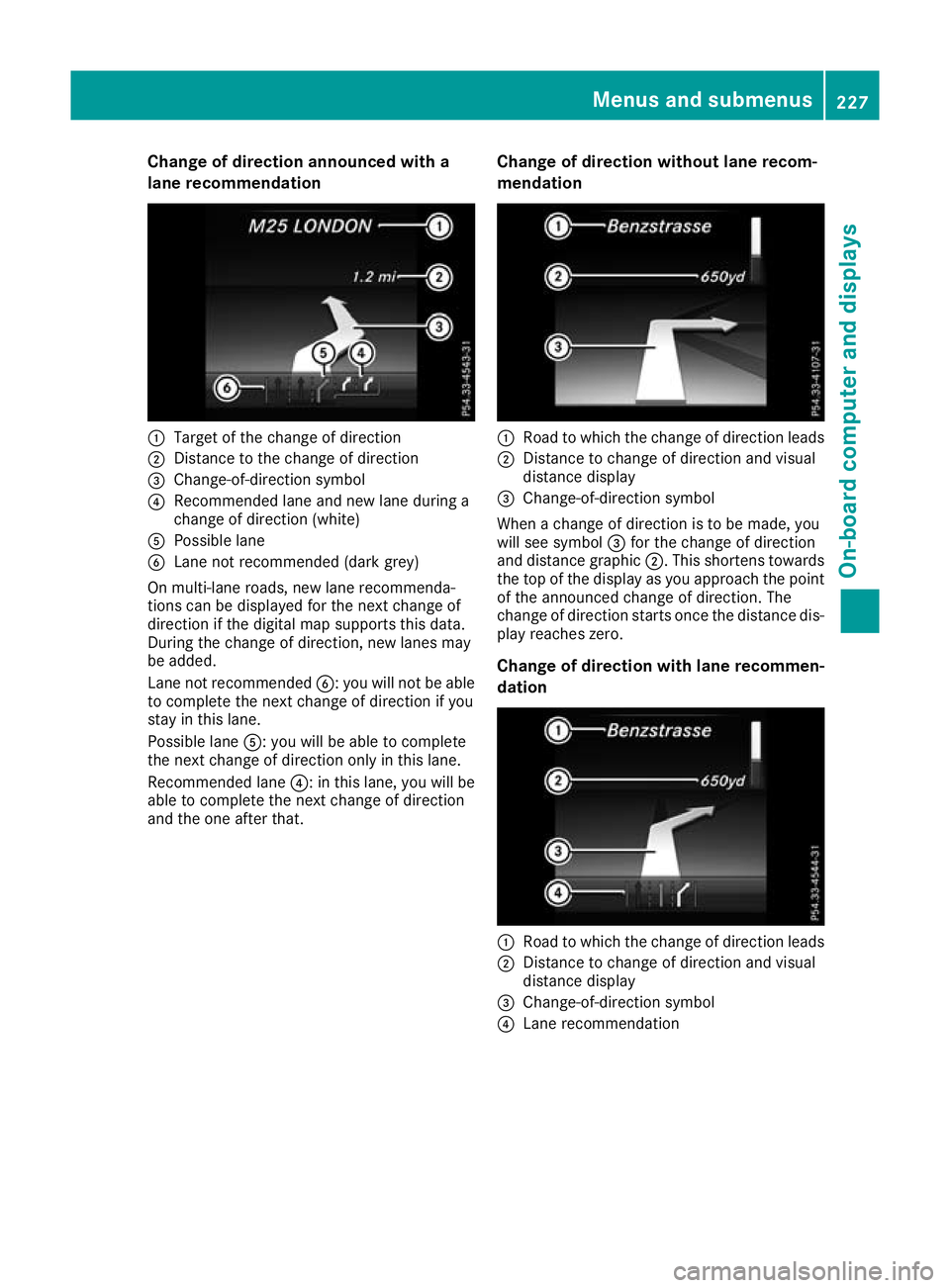
Change of direction announced with a
lane recommendation :
Target of the change of direction
; Distance to the change of direction
= Change-of-direction symbol
? Recommended lane and new lane during a
change of direction (white)
A Possible lane
B Lane not recommended (dark grey)
On multi-lane roads, new lane recommenda-
tions can be displayed for the next change of
direction if the digital map supports this data.
During the change of direction, new lanes may
be added.
Lane not recommended B: you will not be able
to complete the next change of direction if you
stay in this lane.
Possible lane A: you will be able to complete
the next change of direction only in this lane.
Recommended lane ?: in this lane, you will be
able to complete the next change of direction
and the one after that. Change of direction without lane recom-
mendation :
Road to which the change of direction leads
; Distance to change of direction and visual
distance display
= Change-of-direction symbol
When a change of direction is to be made, you
will see symbol =for the change of direction
and distance graphic ;. This shortens towards
the top of the display as you approach the point of the announced change of direction. The
change of direction starts once the distance dis-
play reaches zero.
Change of direction with lane recommen-
dation :
Road to which the change of direction leads
; Distance to change of direction and visual
distance display
= Change-of-direction symbol
? Lane recommendation Menus and submenus
227On-board computer and displays Z