clock MERCEDES-BENZ E-CLASS COUPE 2017 Owners Manual
[x] Cancel search | Manufacturer: MERCEDES-BENZ, Model Year: 2017, Model line: E-CLASS COUPE, Model: MERCEDES-BENZ E-CLASS COUPE 2017Pages: 541, PDF Size: 10.71 MB
Page 104 of 541

3
Stow age compartment in the front cent re
console wi tha USB port (depending on the
ve hicle's equipment)
4 Glovebox
Locking/unlocking thegl ove box
Obser vethe no tes on loading theve hicle
(→ page 99). #
Turn the emer gency key a quarter turn clock‐
wise 2(to lock) or anti-clockwise 1(to
unlock).
Opening the spectacles compa rtment
Obse rveth e no tes on loading theve hicle
(→ page 99). #
Toopen: press button 1. Th
rough-loading feature in there ar ben ch
seat Fo
lding there ar seat backrest forw ards &
WARNING Risk of inju ryifth ere ar
ben chseat/rear seat and seat backrest
are not engaged
If th ere ar ben chseat/rear seat and seat
backrest are not engaged they could fold for‐
wa rds, e.g. when braking suddenly or in the
ev ent of an accident.
R Ifth is is the case, theve hicle occupant
wo uld be forc ed into the seat belt bythe
re ar ben chseat/rear seat or bythe seat
backrest. The seat belt cann otprotect as
intended and could result in additional
injur y.
R Objects or loads in the boot cann otbe
re stra ined bythe seat backrest. #
Make sure that the seat backrest and
th ere ar ben chseat/rear seat are
engaged before everytrip. Seats and
stowing 101
Page 160 of 541
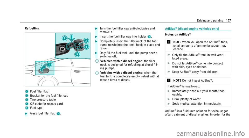
Re
fuelling 1
Fuelfiller flap
2 Brac ketfo rth e fuel filler cap
3 Tyre pressure table
4 QR code forre scue card
5 Fuel type #
Press fuel filler flap 1. #
Turn the fuel filler cap anti-clockwise and
re mo veit. #
Insert the fuel filler cap into holder 2. #
Comple tely inse rtthefiller neck of the fuel
pump nozzle into theta nk, hook in place and
re fuel. #
Only fill th e fuel tank until the pump nozzle
switches off.
% Vehicles with a diesel engine: thefiller
neck is designed forre fuelling at diesel fill‐
ing pumps.
% Vehicles with a diesel engine: whenthe
fuel tank is compl etely em pty, refuel with at
lea st5 litres of diesel. Ad
Blue ®
(diesel engine vehicles only) Note
s onAdBlue ®
* NOTEWhen you open theAd Blue ®
tank,
small amounts of ammonia vapour may
escape. #
Only fill th eAd Blue ®
tank in well-venti‐
lated areas. #
Do not let AdBlue ®
come into contact
wi th skin, eyes or clo thes. #
Keep AdBlue ®
aw ay from children. *
NOTEDo not ingest AdBlue ®
. If
Ad Blue ®
is swallo wed: #
Immediately rinse out your mouth thor‐
oughl y. #
Drink plenty of water. #
Seek medical attention immediately. Ad
Blue ®
is a fluid urea solution forex haust gas
af te rtre atment of diesel engines. In order forthe Driving and pa
rking 157
Page 162 of 541
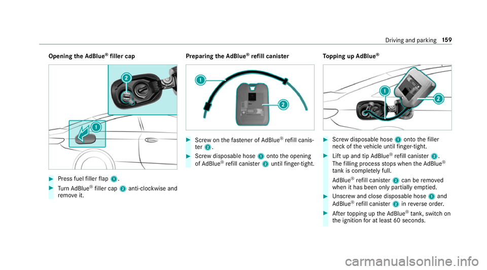
Opening
theAd Blue ®
filler cap #
Press fuel filler flap 1. #
Turn AdBlue ®
filler cap 2anti-clockwise and
re mo veit. Preparing
theAd Blue ®
re fill canis ter #
Screw onthefast ener of AdBlue ®
re fill canis‐
te r2. #
Screw disposable hose 1onto the opening
of Ad Blue ®
re fill canis ter2 until finger-tight. To
pping up AdBlue ® #
Screw disposable hose 1onto thefiller
neck of theve hicle until finger-tight. #
Lift up and tip AdBlue ®
re fill canis ter2.
The filling process stops when theAd Blue ®
ta nk is compl etely full.
Ad Blue ®
re fill canis ter2 can be remo ved
when it has been only partially em ptied. #
Unscr ew and close disposable hose 1and
Ad Blue ®
re fill canis ter2 inreve rse order. #
Afterto pping up theAd Blue ®
tank, switch on
th e ignition for at least 60 seconds. Driving and parking
15 9
Page 233 of 541
Re
quirements:
Before coupling up the trailer, the ball neck must
be fully extended and engaged in the securely
loc ked position.
Tr ailers with a 7-pin plug can be connec tedto
th eve hicle:
R adap ter plug
R adapte r cable
In order forth e trailer tobe recognised bythe
ve hicle:
R the electrical connection must be set up cor‐
re ctly
R the trailer lighting sy stem must be in working
order
The operation of thefo llowing sy stems depends
on the trailer being connected cor rectly:
R ESP ®
R Parking Assist PARKTRONIC
R Parking Pilot
R Blind Spot Assist or Active Blind Spot Assi st
R Active Lane Keeping Assist Coupling up a trailer
* NO
TEDama getothe battery due tofull
discharge Charging
the trailer battery using the po wer
supply of the trailer can damage the batter y. #
Do not use the po wer supp lyto charge
th e trailer batter y. #
Remo vethe pr otective co vering from the ball
head and store it in a safe place. #
Position the trailer on a le vel sur face behind
th eve hicle and couple it up totheve hicle. #
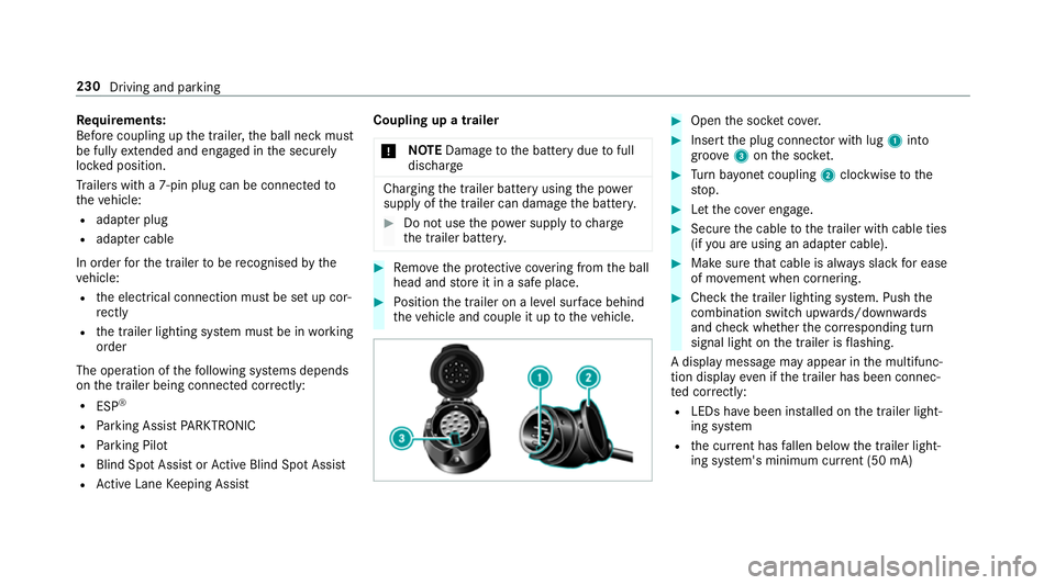
Open the soc ket co ver. #
Insert the plug connector with lug 1into
groo ve3 onthe soc ket. #
Turn bayonet coupling 2clockwise tothe
st op. #
Let the co ver engage. #
Secure the cable tothe trailer with cable ties
(if you are using an adap ter cable). #
Make sure that cable is alw ays slack for ease
of mo vement when cornering. #
Check the trailer lighting sy stem. Push the
combination switch up wards/down wards
and check whe ther the cor responding turn
signal light on the trailer is flashing.
A display message may appear in the multifunc‐
tion display even if the trailer has been connec‐
te d cor rectly:
R LEDs ha vebeen ins talled on the trailer light‐
ing sy stem
R the cur rent has fallen below the trailer light‐
ing sy stem's minimum cur rent (50 mA) 230
Driving and pa rking
Page 361 of 541
#
Follow the instructions in the service
inter val display rega rding the oil
ch ange. *
NO
TEDama gecaused bytopping up too
much engine oil To
pping up too much engine oil can cause
damage tothe engine or the catalytic con‐
ve rter. #
Have excess engine oil remo ved at a
qu alified specialist workshop. #
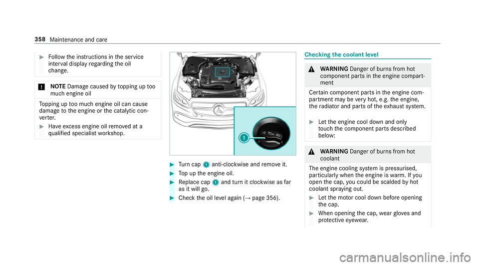
Turn cap 1anti-clockwise and remo veit. #
Top up the engine oil. #
Replace cap 1and turn it clockwise as far
as it will go. #
Check the oil le vel again (→ page 356). Checking
the coolant le vel &
WARNING Danger of bu rns from hot
component parts in the engine compart‐
ment
Cer tain component parts in the engine com‐
partment may be very hot, e.g. the engine,
th era diator and parts of theex haust sy stem. #
Let the engine cool down and only
to uch the component parts described
below: &
WARNING Danger of bu rns from hot
coolant
The engine cooling sy stem is pressurised,
particularly when the engine is warm. If you
open the cap, you could be scalded byhot
coolant spr aying out. #
Let the mo tor cool down before opening
th e cap. #
When opening the cap, wearglove s and
pr otective eyew ear. 358
Maintenance and care
Page 362 of 541
#
Slowly turn the cap half a turn toallow
pressure toescape. #
Park theve hicle on a flat sur face. #
Check the coolant temp erature display in the
instrument clus ter.
The coolant temp erature must be below
70 °C. #
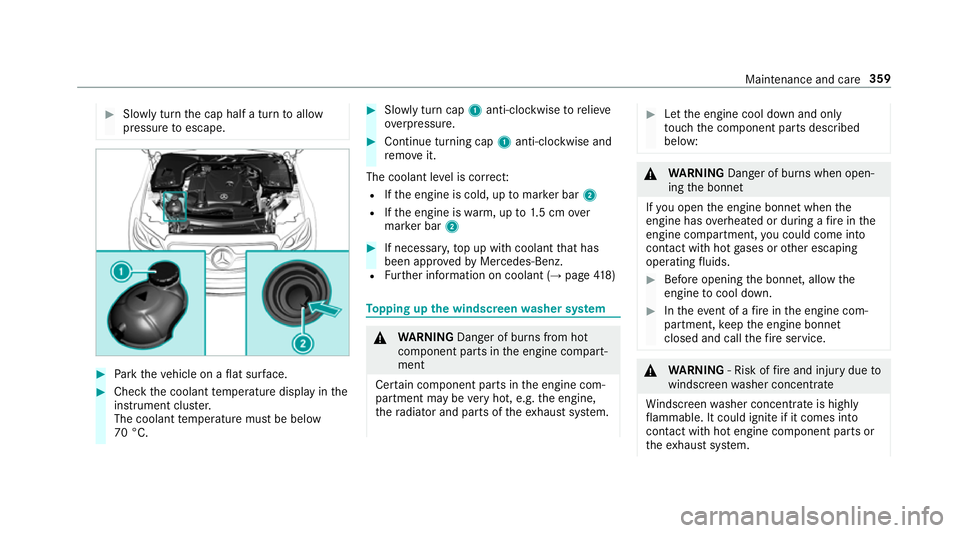
Slowly turn cap 1anti-clockwise torelie ve
ov erpressure. #
Continue turning cap 1anti-clockwise and
re mo veit.
The coolant le vel is cor rect:
R Ifth e engine is cold, up tomar ker bar 2
R Ifth e engine is warm, up to1.5 cm over
mar ker bar 2 #
If necessar y,top up with coolant that has
been appr ovedby Mercedes-Benz.
R Further information on coolant (→ page418) To
pping up the windsc reen washer sy stem &
WARNING Danger of bu rns from hot
component parts in the engine compart‐
ment
Cer tain component parts in the engine com‐
partment may be very hot, e.g. the engine,
th era diator and parts of theex haust sy stem. #
Let the engine cool down and only
to uch the component parts described
below: &
WARNING Danger of bu rns when open‐
ing the bonn et
If yo u open the engine bonn etwhen the
engine has overheated or during a fire inthe
engine compartment, you could come into
contact with hot gases or other escaping
operating fluids. #
Before opening the bonn et, allow the
engine tocool down. #
Intheeve nt of a fire inthe engine com‐
partment, keep the engine bonn et
closed and call thefire service. &
WARNING ‑ Risk of fire and injury due to
windscreen washer concentrate
Wi ndsc reen washer concentrate is highly
fl ammable. It could ignite if it comes into
con tact wi thhot engine component parts or
th eex haust sy stem. Maintenance and care
359
Page 387 of 541
Fi
tting the towing eye #
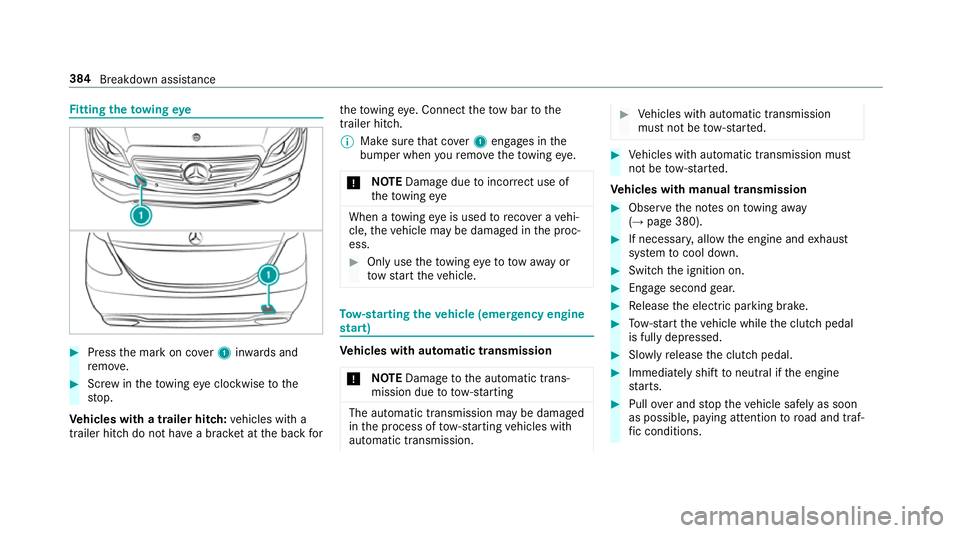
Press the mark on co ver1 inwa rds and
re mo ve. #
Screw intheto wing eyeclockwise tothe
st op.
Ve hicles with a trailer hitch: vehicles with a
trailer hitch do not ha vea brac ket at the back forth
eto wing eye. Connect theto w bar tothe
trailer hitch.
% Makesure that co ver1 engages in the
bumper when youre mo vetheto wing eye.
* NO
TEDama gedue toincor rect use of
th eto wing eye When a
towing eye is used toreco ver a vehi‐
cle, theve hicle may be damaged in the proc‐
ess. #
Only use theto wing eyeto to waw ay or
to w start theve hicle. To
w- starting theve hicle (eme rgency engine
st art) Ve
hicles with automatic transmission
* NO
TEDama getothe automatic trans‐
mission due to tow-starting The automatic transmission may be damaged
in the process of tow- starting vehicles with
automatic transmission. #
Vehicles with automatic transmission
must not be tow- star ted. #
Vehicles with automatic transmission must
not be tow- star ted.
Ve hicles with manual transmission #
Obser vethe no tes on towing away
( → page 380). #
If necessar y,allow the engine and exhaust
sy stem tocool down. #
Switch the ignition on. #
Enga gesecond gear. #
Release the electric parking brake. #
Tow- start theve hicle while the clutch pedal
is fully depressed. #
Slowly release the clutch pedal. #
Immediately shift toneutral if the engine
st arts. #
Pull over and stop theve hicle safely as soon
as possible, paying attention toroad and traf‐
fi c conditions. 384
Breakdown assis tance
Page 404 of 541
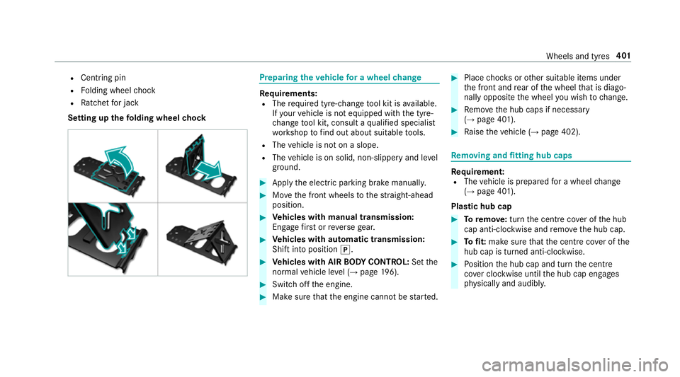
R
Centring pin
R Folding wheel chock
R Ratchet for jack
Setting up thefo lding wheel chock Prepa
ring theve hicle for a wheel change Re
quirements:
R The requ ired tyre-change tool kit is available.
If yo ur vehicle is not equipped with the tyre-
ch ange tool kit, consult a qualified specialist
wo rkshop tofind out about suitable tools.
R The vehicle is not on a slope.
R The vehicle is on solid, non-slippery and le vel
ground. #
Apply the electric parking brake manually. #
Movethe front wheels tothest ra ight-ahead
position. #
Vehicles with manual transmission:
Engage firs t or reve rsege ar. #
Vehicles with automatic transmission:
Shift into position j. #
Vehicles with AIR BODY CONT ROL:Set the
normal vehicle le vel (→ page 196). #
Switch off the engine. #
Make sure that the engine cann otbe star ted. #
Place choc ks orother suitable items under
th e front and rear of the wheel that is diago‐
nally opposite the wheel you wish tochange. #
Remo vethe hub caps if necessary
(→ page 401). #
Raise theve hicle (→ page 402). Re
moving and fitting hub caps Re
quirement:
R The vehicle is prepared for a wheel change
(→ page 401).
Pla stic hub cap #
Toremo ve:turn the cent recover of the hub
cap anti-clockwise and remo vethe hub cap. #
Tofit: make sure that the cent recover of the
hub cap is turned anti-clockwise. #
Position the hub cap and turn the cent re
co ver clockwise until the hub cap engages
ph ysically and audibly. Wheels and tyres
401
Page 405 of 541
Aluminium hub cap
#
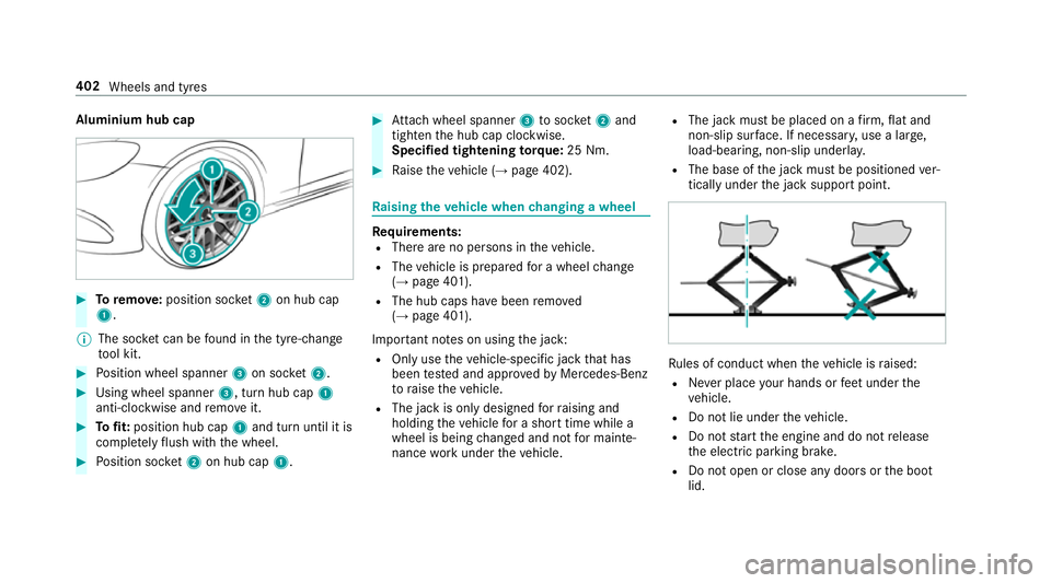
Toremo ve:position soc ket2 on hub cap
1.
% The soc ket can be found in the tyre-change
to ol kit. #
Position wheel spanner 3on soc ket2. #
Using wheel spanner 3, turn hub cap1
anti-clo ckwise and remo veit. #
Tofit: position hub cap 1and turn until it is
comple tely flush with the wheel. #
Position soc ket2 on hub cap 1. #
Attach wheel spanner 3tosoc ket2 and
tighten the hub cap clockwise.
Specified tightening torq ue: 25 Nm. #
Raise theve hicle (→ page 402). Ra
ising theve hicle when changing a wheel Re
quirements:
R There are no persons in theve hicle.
R The vehicle is prepared for a wheel change
(→ page 401).
R The hub caps ha vebeen remo ved
( → page 401).
Impor tant no tes on using the jack:
R Only use theve hicle-specific jack that has
been tested and appr ovedby Mercedes-Benz
to raise theve hicle.
R The jack is only designed forra ising and
holding theve hicle for a short time while a
wheel is being changed and not for mainte‐
nance workunder theve hicle. R
The jack must be placed on a firm ,fl at and
non-slip sur face. If necessar y,use a lar ge,
load-bearing, non-slip underla y.
R The base of the jack must be positioned ver‐
tically under the jack support point. Ru
les of conduct when theve hicle is raised:
R Never place your hands or feet under the
ve hicle.
R Do not lie under theve hicle.
R Do not start the engine and do not release
th e electric parking brake.
R Do not open or close any doors or the boot
lid. 402
Wheels and tyres
Page 407 of 541
#
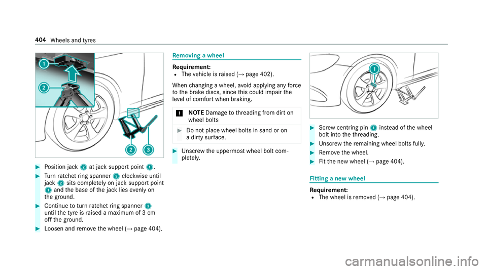
Position jack 2at jack support point 1.#
Turn ratchet ring spanner 3clockwise until
jack 2sits comple tely on ja cksupport point
1 and the base of the jack lies evenly on
th e ground. #
Continue toturn ratchet ring spanner 3
until the tyre is raised a maximum of 3 cm
off the ground. #
Loosen and remo vethe wheel (→ page 404). Re
moving a wheel Re
quirement:
R The vehicle is raised (→ page 402).
When changing a wheel, avoid applying any force
to the brake discs, since this could impair the
le ve l of com fort when braking.
* NO
TEDama getothre ading from dirt on
wheel bolts #
Do not place wheel bolts in sand or on
a dirty sur face. #
Unscr ew the uppermost wheel bolt com‐
ple tely. #
Screw centring pin 1instead of the wheel
bolt into theth re ading. #
Unscr ew there maining wheel bolts fully. #
Remo vethe wheel. #
Fitthe new wheel (→ page 404). Fi
tting a new wheel Re
quirement:
R The wheel is remo ved (→ page 404). 404
Wheels and tyres