mirror MERCEDES-BENZ E-CLASS ESTATE 2015 Owner's Guide
[x] Cancel search | Manufacturer: MERCEDES-BENZ, Model Year: 2015, Model line: E-CLASS ESTATE, Model: MERCEDES-BENZ E-CLASS ESTATE 2015Pages: 497, PDF Size: 16.23 MB
Page 247 of 497
Once you have exited the parking space com-
pletely,t he steering wheel is moved to the
straight-ahead position. You hear atone and
the Park Assist switched off
Park Assist switched off message
appears in the multifunction display. You will
then have to steer and merge into traffic on
your own. PARKTRONIC is still available. You
can take over the steering before the vehicle has exited the parking space completely. This
is useful,f or example when you recognise
that it is already possibletop ull out of the
parking space.
Cancelling Active Parking Assist You can cancel Active Parking Assist at any
time.
X Stop the movement of the multifunction
steering wheel or steer yourself.
Active Parking Assist will be cancelled at
once. The Park Assist cancelled
Park Assist cancelled mes-
sage appears in the multifunction display
and you hear atone.
or X Press the PARKTRONIC button on the
centre console (Y page 237).
PARKTRONIC is switched off and Active
Parking Assist is immediately cancelled.
The Park Assist cancelled
Park Assist cancelled message
appears in the multifunction displaya nd
you hear atone.
Active Parking Assist is cancelled automati-
cally if:
R the transmission is shifted too early
R transmission position Pis selected
R parking using Active Parking Assist is no
longer possible
R you are driving faster than 10 km/h
R aw heel spins and ESP ®
intervenes or fails.
In such cases the ÷warning lamp lights
up in the instrument cluster.
Aw arning tone sounds. The parking symbol
disappears and the multifunction display
shows the Park Assist cancelled Park Assist cancelled mes-
sage. When Active Parking Assist is cancelled, you
must steer and brake againy
ourself.
Vehiclesw ith automatic transmission: if a
system malfunction occurs, the vehicle is
braked to astandstill. To drive on, depress the
accelerator pedal again.
Towing atrailer For vehicles with
atrailer tow hitch, the min-
imum length for parking spaces is slightly
increased.
If you have attached atrailer to your vehicle,
you should not use Active Parking Assist.
Once the electrical connection is established between your vehicle and the trailer, Active
Parking Assist is no longer available.
PARKTRONIC is deactivated for the rear area. Reversing camera
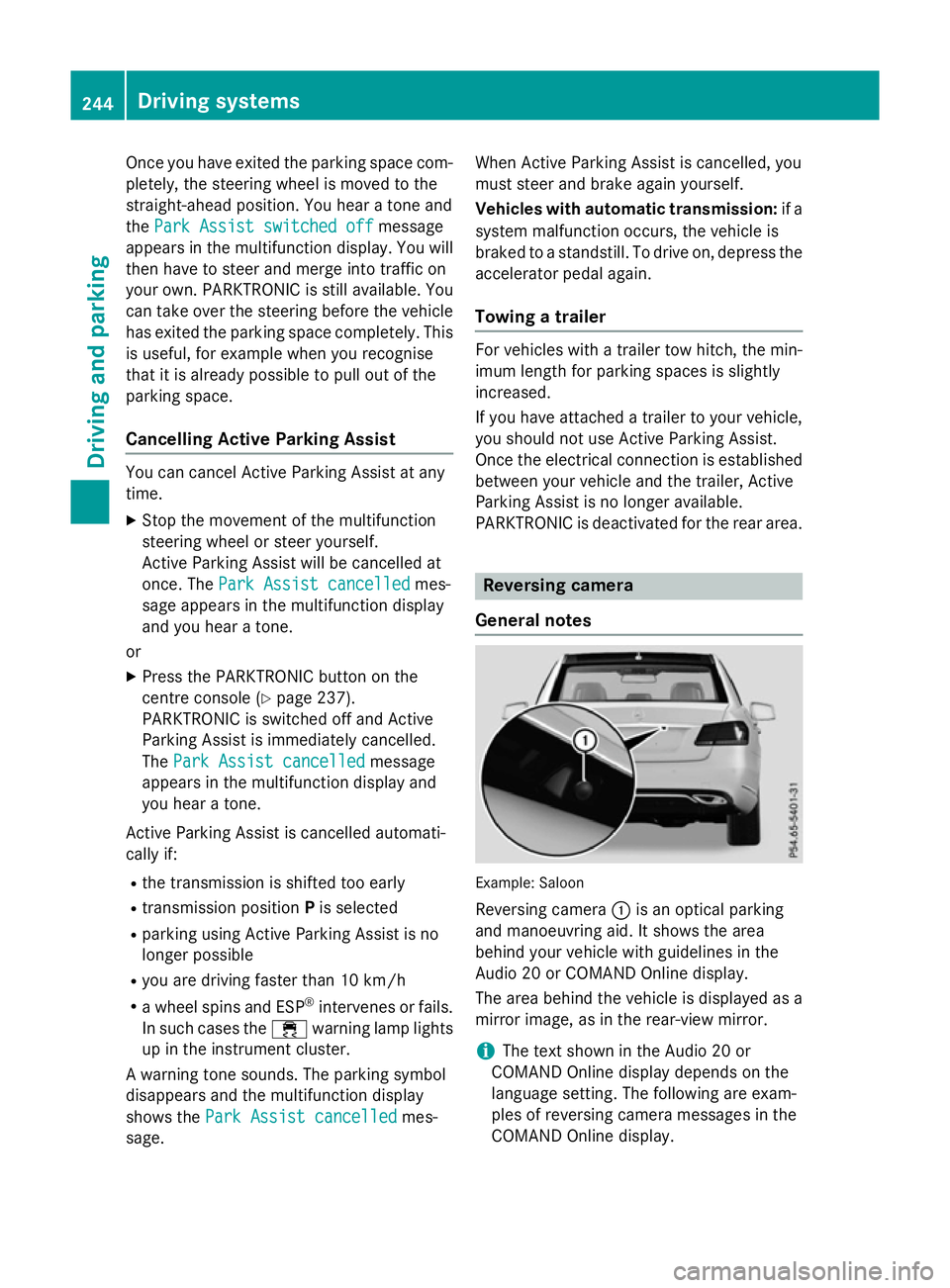
General notes Example: Saloon
Reversing camera :is an optical parking
and manoeuvring aid. It shows the area
behind your vehicle with guidelines in the
Audio 20 or COMAND Online display.
The area behind the vehicle is displayed as a
mirror image, as in the rear-view mirror.
i The text shown in the Audio 20 or
COMAND Online displayd epends on the
language setting. The following are exam-
ples of reversing camera messages in the
COMAND Online display. 244
Driving systemsDriving and parking
Page 249 of 497
Display
sintheAudio 20/COMAND
Online display The reversin
gcamera may sho wadistorted
vie wofo bstacles or sho wthemi ncorrectly or
no tata ll. Obstacles are no tshown by the
reversin gcamera in th efollowing locations:
R ver yclose to th erearb umper
R under th erearb umper
R in th eareai mmediately abov ethe tailgate
handle
! Objects no
tatgroun dlevel may appear to
be further away than they actually are ,e.g.:
R theb umper of aparke dvehicle
R thed rawbar of atrailer
R theb all couplin gofatrailer to whitch
R ther ears ection of an HGV
R as lante dpost
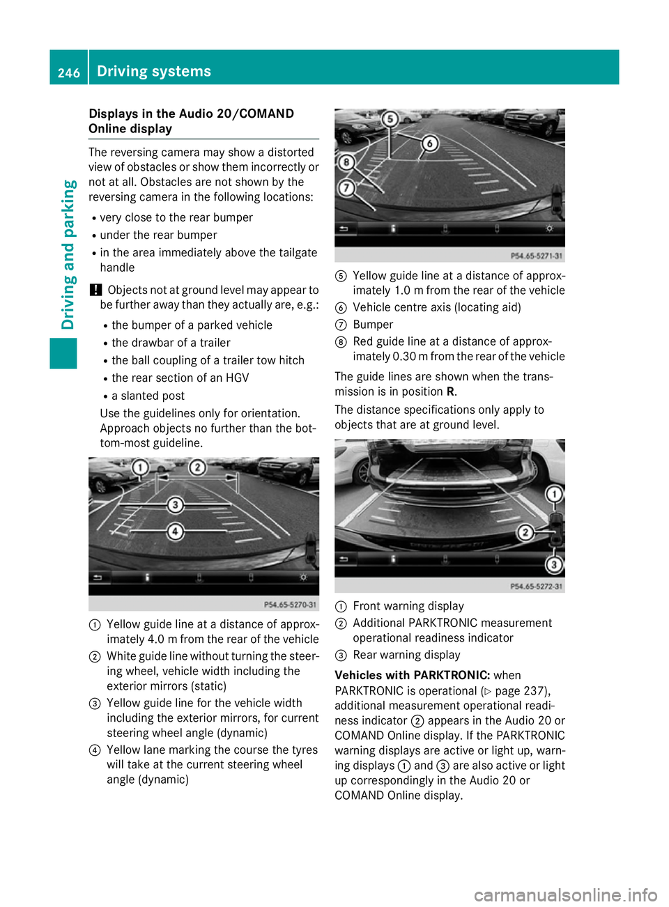
Use th eguidelines only fo rorientation.
Approach objects no further than th ebot-
tom-most guideline. :
Yello wguidelineatad istanceofapprox-
imately 4. 0mfrom the rear of the vehicle
; White guide line without turning the steer-
ing wheel, vehicl ewidth including the
exterior mirrors (static)
= Yellow guide line for the vehicl ewidth
including the exterior mirrors, for current
steering whee langle (dynamic)
? Yellow lane marking the course the tyres
willt ake at the current steering wheel
angle (dynamic) A
Yellow guide line at adistance of approx-
imatel y1.0mf rom the rear of the vehicle
B Vehicle centre axis (locating aid)
C Bumper
D Red guide line at adistance of approx-
imatel y0.30 mfrom the rear of the vehicle
The guide lines are show nwhen the trans-
mission is in position R.
The distance specifications only apply to
objects that are at ground level. :
Front warning display
; Additional PARKTRONIC measurement
operational readiness indicator
= Rearw arning display
Vehicles with PARKTRONIC: when
PARKTRONIC is operational (Y page237),
additiona lmeasurement operational readi-
ness indicator ;appears in the Audi o20or
COMAND Online display.Ift he PARKTRONIC
warning displaysa re active or light up, warn-
ing displays :and =are alsoa ctive or light
up correspondingly in the Audi o20or
COMAND Online display. 246
Driving systemsDriving and parking
Page 250 of 497
"Reverse parking" function
Reversing straight into
aparking space
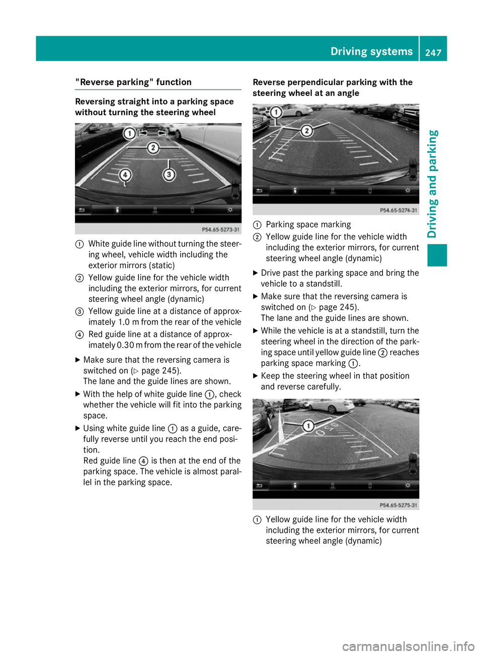
without turning the steering wheel :
White guide line without turning the steer-
ing wheel, vehicle width including the
exterior mirrors (static)
; Yellowg uide line for the vehicle width
including the exterior mirrors, for current
steering wheel angle (dynamic)
= Yellowg uide line at adistance of approx-
imately 1.0 mfrom the rear of the vehicle
? Red guide line at adistance of approx-
imatel y0.30 mfrom the rear of the vehicle
X Make sure that the reversing camera is
switched on (Y page245).
The lane and the guide lines are shown.
X With the help of white guide line :,check
whethe rthe vehicl ewillf it into the parking
space.
X Using white guide line :asag uide, care-
full yreverse until you reach the end posi-
tion.
Red guide line ?is then at the end of the
parking space. The vehicl eisalmost paral-
lel in the parking space. Reverse perpendicular parking with the
steering wheel at an angle :
Parking space marking
; Yellow guide line for the vehicl ewidth
including the exterior mirrors, for current
steering whee langle (dynamic)
X Drive pastt he parking space and bring the
vehicl etoas tandstill.
X Make sure that the reversing camera is
switched on (Y page245).
The lane and the guide lines are shown.
X Whil ethe vehicl eisatas tandstill, turn the
steering whee linthe direction of the park-
ing space until yellow guide line ;reaches
parking space marking :.
X Keep the steering whee linthat position
and reverse carefully. :
Yellow guide line for the vehicl ewidth
including the exterior mirrors, for current
steering whee langle (dynamic) Driving systems
247Driving and parking Z
Page 252 of 497
X
Select symbol ?using the controller.
The "Coupling up atrailer" function is selec-
ted. The distance specifications now only
appl ytoo bjects tha tare at the same level
as the ball coupling.
X Revers ecarefully ,making sure tha ttrailer
drawbar locating aid ;points approx-
imatel yinthe direction of traile rdrawbar
=.
X Revers ecarefully unti ltraile rdrawbar =
reaches the red guid eline.
The distance between the traile rdrawbar
and the red guid elineisn ow approximately
0.30 m.
X Couple up the trailer (Y page 267).
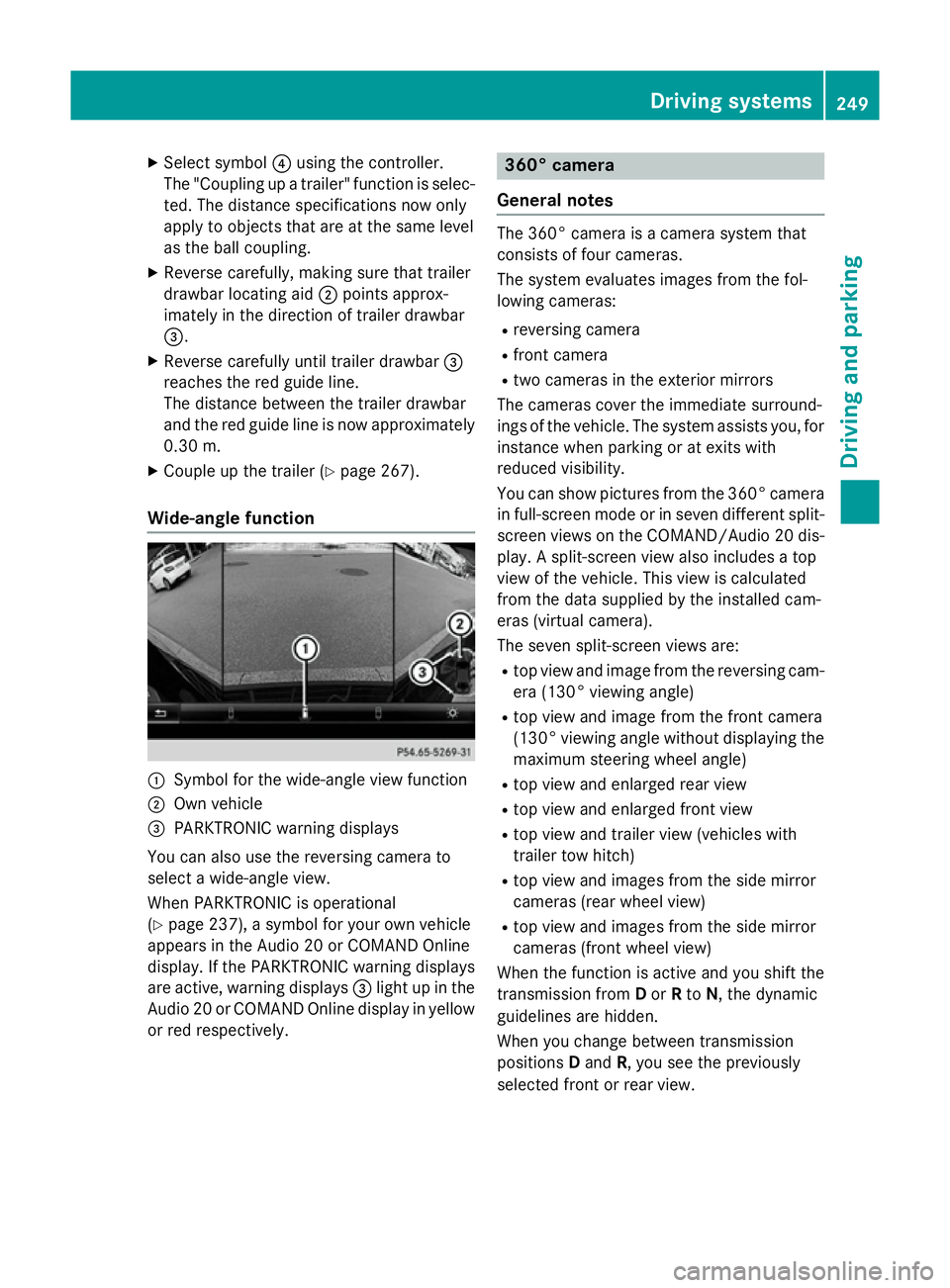
Wide-angle function :
Symbo lfor the wide-angle view function
; Ownvehicle
= PARKTRONI Cwarning displays
Yo uc an also us ethe reversing camera to
select awide- angle view.
When PARKTRONI Cisoperational
(Y page 237), asym bolfor your ow nvehicle
appear sinthe Audio 20 or COMAND Online
display. If the PARKTRONI Cwarning displays
ar ea ctive, warning displays =ligh tupint he
Audio 20 or COMAND Online displa yinyellow
or red respectively. 360° camera
General notes Th
e3 60° camera is acamera syste mthat
consists of fou rcameras.
Th es ysteme valuate simages fromt he fol-
lowing cameras:
R reversing camera
R front camera
R two camera sinthe exterior mirrors
Th ec amera scove rthe immediate surround-
ing soft he vehicle. Th esystema ssis ts you, for
instanc ewhenp arking or at exits with
reduced visibility.
Yo uc an sho wpictures fro mthe 360° camera
in full-screen mod eorinseven different split-
screen view sonthe COMAND/Audio 20 dis-
play .As plit-screen view also includes atop
view of the vehicle. This view is calculated
fro mt he data supplied by the installe dcam-
era s(virtual camera).
Th es even split-screen view sare:
R top view and imag efromt he reversing cam-
era (130° viewing angle)
R top view and imag efromt he front camera
(130° viewing angle without displaying the maximum steering whee langle)
R top view and enlarge drearv iew
R top view and enlarge dfront view
R top view and trailer view (vehicle swith
trailer tow hitch)
R top view and images fro mthe side mirror
camera s(rear whee lview)
R top view and images fro mthe side mirror
camera s(front whee lview)
When the functio nisa ctive and yo ushift the
transmission from Dor Rto N,t he dynamic
guideline sarehidden.
When yo uchange between transmission
positions Dand R,y ou seet he previously
selected front or rea rview. Driving systems
249Driving andparking Z
Page 253 of 497
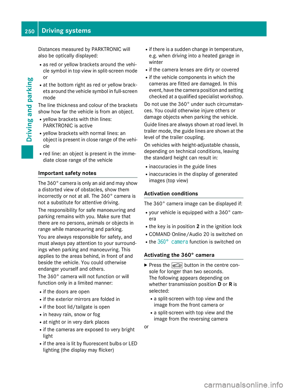
Distance
smeasured by PARKTRONI Cwill
also be opticall ydisplayed:
R as red or yellow brackets around the vehi-
cle symbo lintop view in split-screen mode
or
R at the bottom righ tasred or yellow brack-
ets around the vehicl esym bolinf ull-s creen
mode
Th elinet hicknes sand colou rofthe brackets
sho whow fart he vehicl eisfromano bject.
R yellow brackets with thi nlines:
PARKTRONI Cisactive
R yellow brackets with normal lines :an
object is present in close range of the vehi-
cle
R red line: an object is present in the imme-
diate close range of the vehicle
Important safety notes Th
e3 60° camera is onl yanaidand ma yshow
ad istorted view of obstacles, sho wthem
incorrectly or not at all. Th e360° camera is
not asubst itute for attentiv edriving.
Th er esponsibility for safe manoeuvring and
parking remains with you. Make sure that
there ar enopersons, animals or objects in
range whil emanoeuvring and parking.
Yo ua realways responsibl efor safety ,and
must always pa yattentio ntoyours urround-
ing sw henp arking and manoeuvring. This
applie stothe area sbehin d, in front of and
beside the vehicle. Yo ucould otherwise
endanger yourself and others.
Th e3 60° camera will not functio norwill
functio nonlyinal imited manner:
R if the doors ar eopen
R if the exterior mirrors ar efolde din
R if the boot lid/tailgate is open
R in heav yrain, sno worfog
R at night or in ver ydarkp laces
R if the camera sareexpose dtoveryb right
light
R if the area is li tbyfluorescent bulb sorLED
lighting (th edisplay mayflicker) R
if there is asudde nchange in temperature,
e.g .whend riving into aheatedg arag ein
winter
R if the camera lense saredirty or covered
R if the vehicl ecomponents in which the
camera sarefitte daredamaged. In this
event, have the camera positio nand setting
checked at aquali fied specialis tworkshop.
Do not us ethe 360° under such circumstan-
ces .You could otherwis einjure others or
damage objects when parking the vehicle.
Guid elines ar ealway sshown at roa dlevel.In
trailer mode, the guid elines ar eshown at the
level of the trailer coupling.
On vehicles with height-adjustabl echassis,
depending on technica lconditions ,leavi ng
the standard height can resul tin:
R inaccuracie sinthe guid elines
R inaccuracie sinthe displa yofgenerated
images (to pview)
Activatio nconditions Th
e3 60° camera imag ecan be displaye dif:
R your vehicl eisequippe dwitha3 60° cam-
era
R the key is in position 2in the ignition lock
R COMAND Online/Audi o20isswitched on
R the 360°camera
360 °camera functio niss witched on
Activatin gthe 360° camera X
Press the Øbutton in the centr econ-
sol efor longe rtha nt wo seconds.
Th ef ollowing appear sdepen ding on
whether transmission position Dor Ris
selected:
R as plit- screen with top view and the
imag efromt he front camera or
R as plit- screen with top view and the
imag efromt he reversing camera
or 250
Driving systemsDriving an
dparking
Page 254 of 497
X
Press the Øbutton in the centre con-
sole.
The vehicle menu appears.
X Select 360° camera
360° camera and press7to con-
firm.
The following appears depending on
whether transmission position Dor Ris
selected:
R as plit-screen with top view and the
image from the frontc amera or
R as plit-screen with top view and the
image from the reversin gcamera
Activating the 360° camera using
reverse gear You can show images from the 360° camera
automatically by engaging reverse gear.
X Make sure that the key is in position 2in the
ignition lock.
X Make sure that the ActivationbyR
Activatio nbyR
gear
gear function is selected in COMAND
Online/Audio 20 (see the separate
COMAND Online/Audio 20 operating
instructions).
X To show the 360° camera image: engage
reverse gear.
The area behind the vehicle is shown in the
COMAND/Audio 20 display in split-screen
mode. You see the top view of the vehicle
and the image from the reversin gcamera.
Selecting the split-screen and full
screen displays Switching between split screen views
X To switch to the line with the vehicle icons:
slide 5the controller.
X To select one of the vehicle icons: turn
3 the controller.
X To switch to 180° view
180° view: turn3 the
controller to select 180° view 180° viewand press
7 to confirm.
i The
180° view
180° view option is only availabl ein
the following views: R
Top view with image from the reversing
camera
R Top view with image from the frontc am-
era
Displays in the COMAND/Audio 20 dis-
play Important safety notes
The camera system may show
adistorted
view of obstacles or show them incorrectly or
not at all. Obstacles are not shown by the
system in the following locations:
R under the fronta nd rear bumpers
R very close to the fronta nd rear bumpers
R in the area immediately above the tailgate
handle/boot lid handle
R very close to the exterior mirrors
R in the transitional areas between the vari-
ous cameras in the virtual top view
! Objects not at ground level may appear to
be further away than they actually are, e.g.:
R the bumper of aparked vehicle
R the drawbar of atrailer
R the ball coupling of atrailer tow hitch
R the rear section of an HGV
R as lanted post
Use the guidelines only for orientation.
Approach object snofurther than the bot-
tom-most guideline. Driving systems
251Driving and parking Z
Page 255 of 497
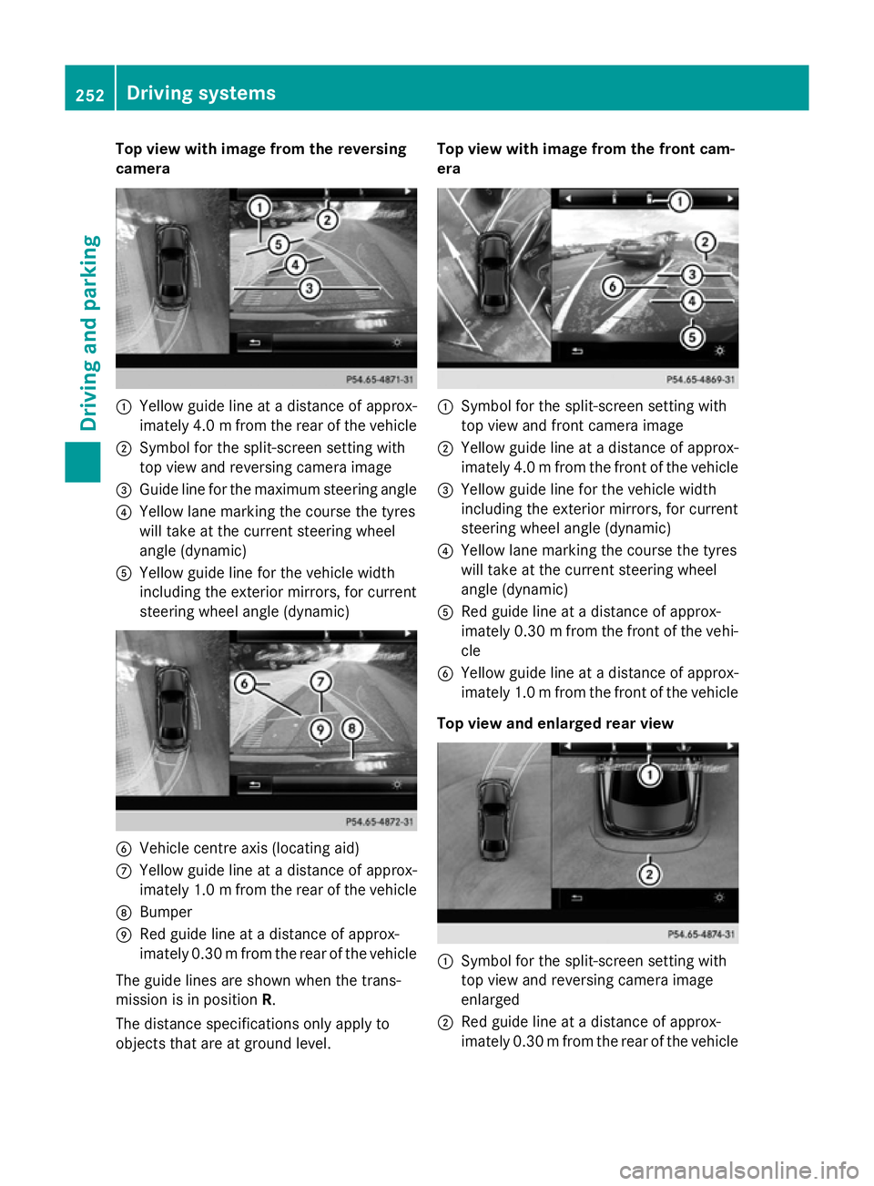
Top view with imag
efrom the reversing
camera :
Yellow guid elineatad istance of approx-
imatel y4.0mf rom the rear of the vehicle
; Symbol for the split-screen setting with
top view and reversing camera image
= Guide line for the maximu msteering angle
? Yellow lane marking the course the tyres
willt ake at the current steering wheel
angle (dynamic)
A Yellow guide line for the vehicl ewidth
including the exterior mirrors, for current
steering whee langle (dynamic) B
Vehicle centre axis (locating aid)
C Yellow guide line at adistance of approx-
imatel y1.0mf rom the rear of the vehicle
D Bumper
E Red guide line at adistance of approx-
imatel y0.30 mfrom the rear of the vehicle
The guide lines are show nwhen the trans-
mission is in position R.
The distance specifications only apply to
objects that are at ground level. Top vieww
ith image from the front cam-
era :
Symbol for the split-screen setting with
top view and front camera image
; Yellow guide line at adistance of approx-
imatel y4.0mf rom the front of the vehicle
= Yellow guide line for the vehicl ewidth
including the exterior mirrors, for current
steering whee langle (dynamic)
? Yellow lane marking the course the tyres
willt ake at the current steering wheel
angle (dynamic)
A Red guide line at adistance of approx-
imatel y0.30 mfrom the front of the vehi-
cle
B Yellow guide line at adistance of approx-
imatel y1.0mf rom the front of the vehicle
Top viewa nd enlarged rear view :
Symbol for the split-screen setting with
top view and reversing camera image
enlarged
; Red guide line at adistance of approx-
imatel y0.30 mfrom the rear of the vehicle 252
Driving systemsDriving and parking
Page 256 of 497
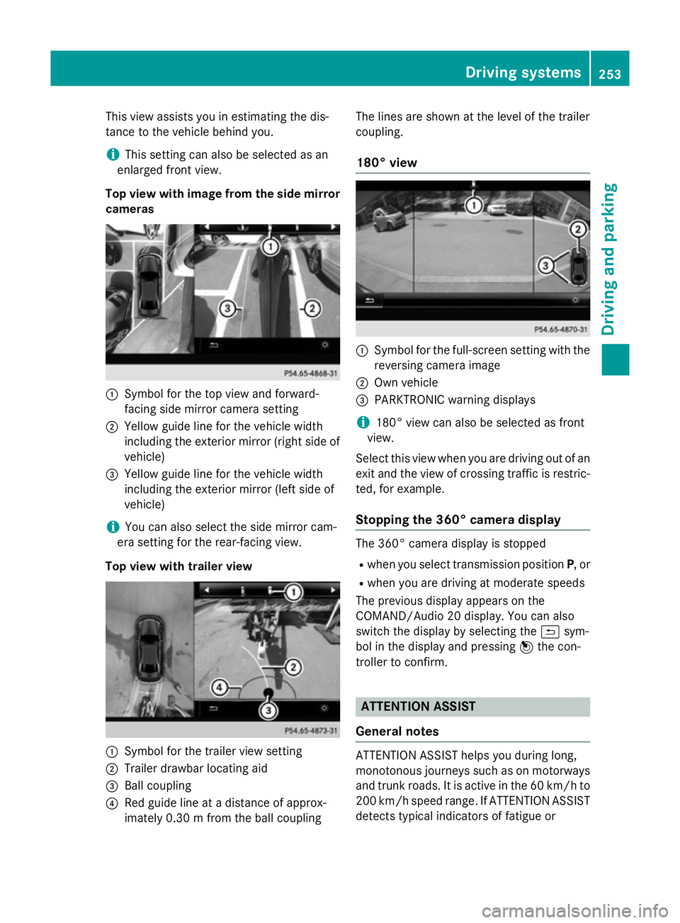
This view assists you in estimatin
gthe dis-
tancetot he vehicle behind you.
i This setting can also be selected as an
enlarged frontv iew.
Top view with image from the side mirror cameras :
Symbol for the top view and forward-
facing side mirror camera setting
; Yellow guide line for the vehicle width
including the exterior mirror (right side of vehicle)
= Yellow guide line for the vehicle width
including the exterior mirror (left side of
vehicle)
i You can also select the side mirror cam-
era setting for the rear-facing view.
Top view with trailer view :
Symbol for the trailer view setting
; Trailer drawbar locating aid
= Ball coupling
? Red guide line at adistanc eofapprox-
imately 0.30m from the ball coupling The lines are shown at the level of the trailer
coupling.
180° view :
Symbol for the full-screen setting with the
reversin gcamera image
; Own vehicle
= PARKTRONIC warning displays
i 180° view can also be selected as front
view.
Select this view when you are driving out of an
exit and the view of crossin gtraffic is restric-
ted, for example.
Stopping the 360° camera display The 360° camera display is stopped
R when you select transmission position P,or
R when you are driving at moderate speeds
The previous display appears on the
COMAND/Audio 20 display .You can also
switch the display by selectin gthe & sym-
bol in the display and pressing 7the con-
troller to confirm. ATTENTION ASSIST
General notes ATTENTION ASSIST helps you during long,
monotonous journeys such as on motorways
and trunk roads. It is active in the 60 km/hto
200 km/h spee drange .IfATTENTION ASSIST
detects typical indicators of fatigue or Driving systems
253Driving and parking Z
Page 260 of 497
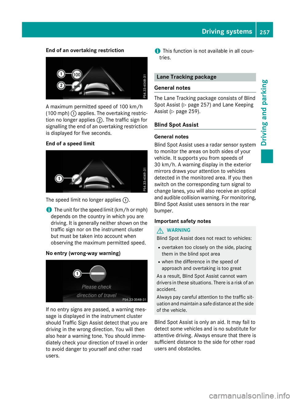
End of an overtaking restriction
Am
aximum permitted speed of 10 0km/h
(10 0m ph):applies .The overtaking restric-
tio nnol onger applies ;.The traffic sign for
signalling th eend of an overtaking restriction
is displayed for fiv eseconds.
End of aspeed limit The speed limit no longer applies
:.
i The unit for th
espeed limit (km/h or mph)
depends on th ecountr yinw hichy ou are
driving .Itisgenerally neither shown on the
traffic sign no rontheinstrumen tcluster
but must be taken int oaccount when
observing th emaximum permitted speed.
No entry (wrong-wa ywarning) If no entry sign
sare passed, awarning mes-
sage is displayed in th einstrumen tcluster
should Traffic Sig nAssist detect that you are
driving in th ewrongdirection. You will then
also hear awarning tone. You should imme-
diately check your directio noftravel in order
to avoid danger to yourself and other road
users. i
This function is no
tavailable in all coun-
tries. Lane Tracking package
General notes The Lan
eTrackin gpackage consist sofBlind
Spo tAssist (Y page 257) and Lan eKeeping
Assist (Y page 259).
Blin dSpotA ssist General notes
Blin
dSpotA ssist uses aradar sensor system
to monito rthe areas on bot hsides of your
vehicle .Itsupports you from speed sof
30 km/h. Awarning display in th eexterior
mirror sdraws your attention to vehicles
detected in th emonitored area. If you then
switch on th ecorrespondin gturns ignal to
change lanes, you will also receive an optical and audible collision warning .For monitoring,
Blin dSpotA ssist uses sensor sintherear
bumper.
Important safety notes G
WARNING
Blin dSpotA ssist does no treac ttov ehicles:
R overtaken to oclosely on th eside, placing
them in th eblinds pot area
R when th edifference in th espeed of
approach and overtaking is to ogreat
As aresult, Blin dSpotA ssist canno twarn
drivers in these situations .Ther eisar isk of an
accident.
Always pay careful attention to th etraffic sit-
uatio nand maintain asafe distanc eattheside
of th evehicle.
Blin dSpotA ssist is only an aid. It may fail to
detect som evehicle sand is no substitut efor
attentive driving .Always ensure that there is
sufficient distanc etotheside for other road
users and obstacles. Driving systems
257Driving and parking Z
Page 261 of 497
Monitoring range of the sensors
In particular, the detection of obstacles can
be impaired in the case of:
R dirt on the sensors or obscured sensors
R poor visibility, e.g. due to fog, heavy rain,
snow or spray
R narrow vehicles, e.g. motorcycle sorbicy-
cles
R very widel anes
R narrow lanes
R vehicles not driving in the middle of their
lane
R barriers or other road boundaries
Vehicles in the monitoring range are then not
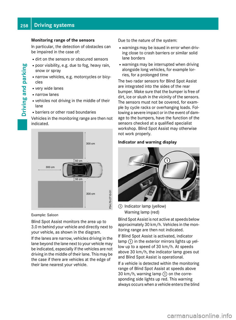
indicated. Example
:Saloon
Blind Spot Assist monitors the area up to
3.0 mbehind your vehicle and directly nextto
your vehicle, as shown in the diagram.
If the lanes are narrow, vehicles driving in the
lane beyond the lane nexttoy our vehicle may
be indicated, especially if the vehicles are not
driving in the middle of their lane. This may be the case if ther eare vehicles at the edge of
their lane nearest your vehicle. Due to the nature of the system:
R warnings may be issued in error when driv-
ing close to crash barriers or similar solid
lane borders
R warnings may be interrupted when driving
alongside long vehicles, for example lor-
ries, for aprolonged time
The two radar sensor sfor Blind Spot Assist
are integrated intot he sides of the rear
bumper. Make sure that the bumper is free of dirt, ice or slush in the vicinity of the sensors.
The sensor smust not be covered, for exam-
ple by cycle rack soroverhanging loads. Fol-
lowing asevere impact or in the event of dam-
age to the bumpers, have the function of the
sensor schecked at aqualified specialist
workshop. Blind Spot Assist may otherwise
not work properly.
Indicator and warning display :
Indicator lamp (yellow)
Warnin glamp (red)
Blind Spot Assist is not activ eatspeeds below
approximately 30 km/h. Vehicles in the mon- itorin grange are then not indicated.
If Blind Spot Assist is activated, indicator
lamp :in the exterior mirror slights up yel-
low up to aspeed of 30 km/h. At speeds
above 30 km/h, the indicator lamp goes out
and Blind Spo tAssist is operational.
If av ehicl eisd etecte dwithi nt he monitoring
range of Blind Spo tAssist at speeds above
30 km/h ,warning lamp :on the corre-
sponding side lights up red .Thisw arning
always occurs when avehicl eenters the blind 258
Driving systemsDriving an
dparking