MERCEDES-BENZ E-CLASS SALOON 2008 Owners Manual
Manufacturer: MERCEDES-BENZ, Model Year: 2008, Model line: E-CLASS SALOON, Model: MERCEDES-BENZ E-CLASS SALOON 2008Pages: 401, PDF Size: 6.89 MB
Page 321 of 401
Flat tyre
318 Make sure that the jack is placed on a firm,
non-slip, level surface. Do not use wooden
blocks or similar as jacking supports. Oth-
erwise, the jack will not be able to achieve
its load-bearing capacity due to the restric-
ted height.
Do not start the engine at any time while
the wheel is being changed.
Do not lie under the vehicle when it is being
supported by the jack. If you do not raise
the vehicle as described, it could slip off the
jack (e.g. if the engine is started or a door
or the boot lid/tailgate is opened or closed)
and you could sustain serious injuries. Using the TIREFIT kit
You can use the TIREFIT kit to seal small
punctures, particularly those in the tyre tread.
You can use TIREFIT in outdoor temperatures
down to -20 °C. G
Risk of accident
In the following situations, your safety is at
particular risk and TIREFIT is unable to pro-
vide breakdown assistance: R
if there are cuts or punctures in the tyre
greater than 4 mm
R if the wheel rim is damaged
R if you have driven at very low tyre pres-
sures or on a flat tyre
Do not drive any further. Consult a qualified
specialist workshop which has the neces-
sary specialist knowledge and tools to carry
out the work required.
Mercedes-Benz recommends that you use
a Mercedes-Benz Service Centre for this
purpose. In particular, work relevant to
safety or on safety-related systems must be
carried out at a qualified specialist work-
shop.
X Do not remove any foreign objects which
have penetrated the tyre, e.g. screws or
nails.
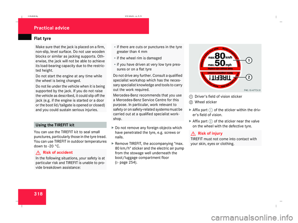
X Remove TIREFIT, the accompanying "max.
80 km/h "sticker and the electric air pump
from the stowage well underneath the
boot/luggage compartment floor
(Y page 254). 1
Driver's field of vision sticker
2 Wheel sticker
X Affix part 1of the sticker within the driv-
er's field of vision.
X Affix part 2of the sticker near the valve
on the wheel with the defective tyre. G
Risk of injury
TIREFIT must not come into contact with
your skin, eyes or clothing. Practical advice
211_AKB; 2; 5, en-GB
mkalafa
, Version: 2.9.4 2008-02-29T16:57:07+01:00 - Seite 318Dateiname: 6515_3416_02_buchblock.pdf; preflight
Page 322 of 401
Flat tyre
319R
If TIREFIT comes into contact with your
eyes or skin, immediately rinse thor-
oughly with clean water.
R Change out of clothing which has come
into contact with TIREFIT immediately.
R If an allergic reaction occurs, consult a
doctor immediately.
Keep TIREFIT away from children.
R If TIREFIT is swallowed, immediately
rinse your mouth out thoroughly with
water and drink plenty of water.
R Do not induce vomiting. Consult a doctor
immediately.
R Do not inhale TIREFIT fumes.
i If TIREFIT leaks out, allow it to dry. It can
then be removed like a layer of film.
If you get TIREFIT on your clothing, have it
cleaned as soon as possible with perchloro-
ethylene. G
Risk of injury
Comply with the manufacturer's safety
instructions shown on the sticker on the
electric air pump. i
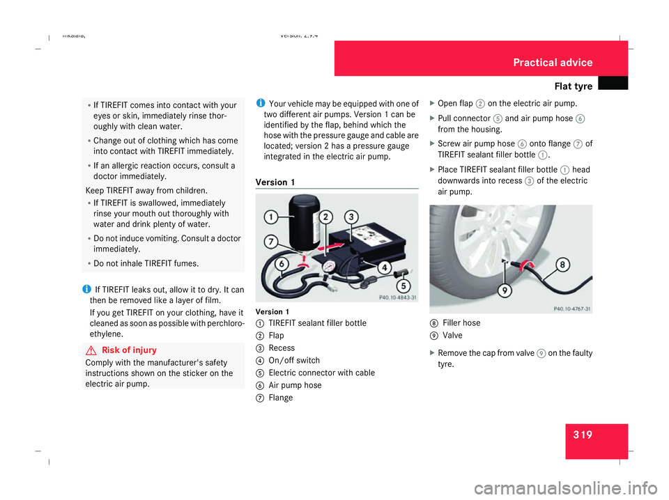
Your vehicle may be equipped with one of
two different air pumps. Version 1 can be
identified by the flap, behind which the
hose with the pressure gauge and cable are
located; version 2 has a pressure gauge
integrated in the electric air pump.
Version 1 Version 1
1
TIREFIT sealant filler bottle
2 Flap
3 Recess
4 On/off switch
5 Electric connector with cable
6 Air pump hose
7 Flange X
Open flap 2on the electric air pump.
X Pull connector 5and air pump hose 6
from the housing.
X Screw air pump hose 6onto flange 7of
TIREFIT sealant filler bottle 1.
X Place TIREFIT sealant filler bottle 1head
downwards into recess 3of the electric
air pump. 8
Filler hose
9 Valve
X Remove the cap from valve 9on the faulty
tyre. Practical advice
211_AKB; 2; 5, en-GB
mkalafa,
Version: 2.9.4 2008-02-29T16:57:07+01:00 - Seite 319 ZDateiname: 6515_3416_02_buchblock.pdf; preflight
Page 323 of 401
Flat tyre
320a
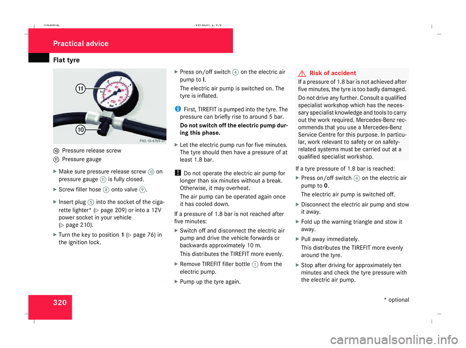
Pressure release screw
b Pressure gauge
X Make sure pressure release screw aon
pressure gauge bis fully closed.
X Screw filler hose 8onto valve 9.
X Insert plug 5into the socket of the ciga-
rette lighter* (Y page 209) or into a 12V
power socket in your vehicle
(Y page 210).
X Turn the key to position 1(Y page 76) in
the ignition lock. X
Press on/off switch 4on the electric air
pump to I.
The electric air pump is switched on. The
tyre is inflated.
i First, TIREFIT is pumped into the tyre. The
pressure can briefly rise to around 5 bar.
Do not switch off the electric pump dur-
ing this phase.
X Let the electric pump run for five minutes.
The tyre should then have a pressure of at
least 1.8 bar.
! Do not operate the electric air pump for
longer than six minutes without a break.
Otherwise, it may overheat.
The air pump can be operated again once
it has cooled down.
If a pressure of 1.8 bar is not reached after
five minutes:
X Switch off and disconnect the electric air
pump and drive the vehicle forwards or
backwards approximately 10 m.
This distributes the TIREFIT more evenly.
X Remove TIREFIT filler bottle 1from the
electric pump.
X Pump up the tyre again. G
Risk of accident
If a pressure of 1.8 bar is not achieved after
five minutes, the tyre is too badly damaged.
Do not drive any further. Consult a qualified
specialist workshop which has the neces-
sary specialist knowledge and tools to carry
out the work required. Mercedes-Benz rec-
ommends that you use a Mercedes-Benz
Service Centre for this purpose. In particu-
lar, work relevant to safety or on safety-
related systems must be carried out at a
qualified specialist workshop.
If a tyre pressure of 1.8 bar is reached:
X Press on/off switch 4on the electric air
pump to 0.
The electric air pump is switched off.
X Disconnect the electric air pump and stow
it away.
X Fold up the warning triangle and stow it
away.
X Pull away immediately.
This distributes the TIREFIT more evenly
around the tyre.
X Stop after driving for approximately ten
minutes and check the tyre pressure with
the electric air pump. Practical advice
* optional
211_AKB; 2; 5, en-GB
mkalafa,
Version: 2.9.4 2008-02-29T16:57:07+01:00 - Seite 320Dateiname: 6515_3416_02_buchblock.pdf; preflight
Page 324 of 401
Flat tyre
321G
Risk of accident
If the tyre pressure is now lower than
1.3 bar, the tyre is too badly damaged. Do
not drive any further. Consult a qualified
specialist workshop which has the neces-
sary specialist knowledge and tools to carry
out the work required. Mercedes-Benz rec-
ommends that you use a Mercedes-Benz
Service Centre for this purpose. In particu-
lar, work relevant to safety or on safety-
related systems must be carried out at a
qualified specialist workshop.
X If the tyre pressure is still at least 1.3 bar,
correct it (see fuel filler flap for values).
To increase the tyre pressure: switch on
the electric air pump.
To reduce the tyre pressure: open pres-
sure release screw aon pressure
gauge b.
X Drive to the nearest workshop and have the
tyre changed there.
X Have the TIREFIT kit replaced as soon as
possible at a qualified specialist workshop,
e.g. at a Mercedes-Benz Service Centre. G
Risk of accident
Do not exceed the maximum speed of 80
km/h.
The “max. 80 km/h” sticker must be affixed
within the driver's field of vision.
The vehicle's handling characteristics may
be affected. H
Environmental note
Have the used TIREFIT kit disposed of pro-
fessionally, e.g. at a Mercedes-Benz
Service Centre.
X Have the TIREFIT kit replaced every four
years at a qualified specialist workshop,
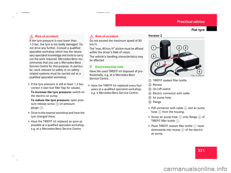
e.g. a Mercedes-Benz Service Centre. Version 2 1
TIREFIT sealant filler bottle
2 Recess
3 On/off switch
4 Electric connector with cable
5 Air pump hose
6 Flange
X Pull connector with cable 4and air pump
hose 5from the housing.
X Screw air pump hose 5onto flange 6of
TIREFIT filler bottle 1.
X Place TIREFIT sealant filler bottle 1head
downwards into recess 2of the electric
air pump. Practical advice
211_AKB; 2; 5, en-GB
mkalafa,
Version: 2.9.4 2008-02-29T16:57:07+01:00 - Seite 321 ZDateiname: 6515_3416_02_buchblock.pdf; preflight
Page 325 of 401
Flat tyre
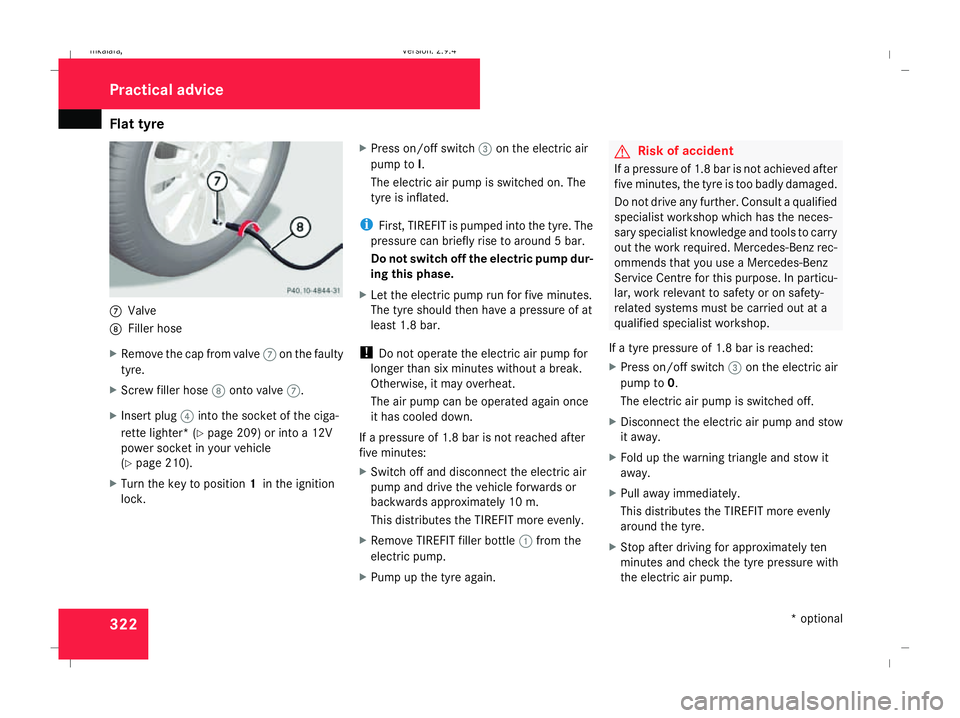
3227
Valve
8 Filler hose
X Remove the cap from valve 7on the faulty
tyre.
X Screw filler hose 8onto valve 7.
X Insert plug 4into the socket of the ciga-
rette lighter* (Y page 209) or into a 12V
power socket in your vehicle
(Y page 210).
X Turn the key to position 1in the ignition
lock. X
Press on/off switch 3on the electric air
pump to I.
The electric air pump is switched on. The
tyre is inflated.
i First, TIREFIT is pumped into the tyre. The
pressure can briefly rise to around 5 bar.
Do not switch off the electric pump dur-
ing this phase.
X Let the electric pump run for five minutes.
The tyre should then have a pressure of at
least 1.8 bar.
! Do not operate the electric air pump for
longer than six minutes without a break.
Otherwise, it may overheat.
The air pump can be operated again once
it has cooled down.
If a pressure of 1.8 bar is not reached after
five minutes:
X Switch off and disconnect the electric air
pump and drive the vehicle forwards or
backwards approximately 10 m.
This distributes the TIREFIT more evenly.
X Remove TIREFIT filler bottle 1from the
electric pump.
X Pump up the tyre again. G
Risk of accident
If a pressure of 1.8 bar is not achieved after
five minutes, the tyre is too badly damaged.
Do not drive any further. Consult a qualified
specialist workshop which has the neces-
sary specialist knowledge and tools to carry
out the work required. Mercedes-Benz rec-
ommends that you use a Mercedes-Benz
Service Centre for this purpose. In particu-
lar, work relevant to safety or on safety-
related systems must be carried out at a
qualified specialist workshop.
If a tyre pressure of 1.8 bar is reached:
X Press on/off switch 3on the electric air
pump to 0.
The electric air pump is switched off.
X Disconnect the electric air pump and stow
it away.
X Fold up the warning triangle and stow it
away.
X Pull away immediately.
This distributes the TIREFIT more evenly
around the tyre.
X Stop after driving for approximately ten
minutes and check the tyre pressure with
the electric air pump. Practical advice
* optional
211_AKB; 2; 5, en-GB
mkalafa,
Version: 2.9.4 2008-02-29T16:57:07+01:00 - Seite 322Dateiname: 6515_3416_02_buchblock.pdf; preflight
Page 326 of 401
Flat tyre
323G
Risk of accident
If the tyre pressure is now lower than
1.3 bar, the tyre is too badly damaged. Do
not drive any further. Consult a qualified
specialist workshop which has the neces-
sary specialist knowledge and tools to carry
out the work required. Mercedes-Benz rec-
ommends that you use a Mercedes-Benz
Service Centre for this purpose. In particu-
lar, work relevant to safety or on safety-
related systems must be carried out at a
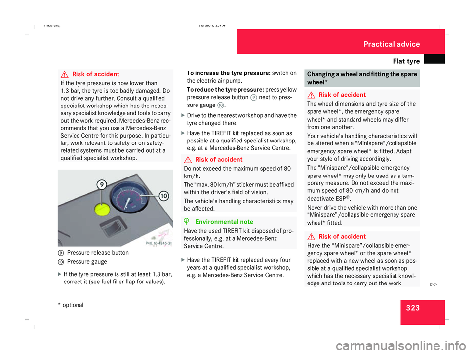
qualified specialist workshop. 9
Pressure release button
a Pressure gauge
X If the tyre pressure is still at least 1.3 bar,
correct it (see fuel filler flap for values). To increase the tyre pressure:
switch on
the electric air pump.
To reduce the tyre pressure: press yellow
pressure release button 9next to pres-
sure gauge a.
X Drive to the nearest workshop and have the
tyre changed there.
X Have the TIREFIT kit replaced as soon as
possible at a qualified specialist workshop,
e.g. at a Mercedes-Benz Service Centre. G
Risk of accident
Do not exceed the maximum speed of 80
km/h.
The “max. 80 km/h” sticker must be affixed
within the driver's field of vision.
The vehicle's handling characteristics may
be affected. H
Environmental note
Have the used TIREFIT kit disposed of pro-
fessionally, e.g. at a Mercedes-Benz
Service Centre.
X Have the TIREFIT kit replaced every four
years at a qualified specialist workshop,
e.g. a Mercedes-Benz Service Centre. Changing a wheel and fitting the spare
wheel*
G
Risk of accident
The wheel dimensions and tyre size of the
spare wheel*, the emergency spare
wheel* and standard wheels may differ
from one another.
Your vehicle's handling characteristics will
be altered when a "Minispare"/collapsible
emergency spare wheel* is fitted. Adapt
your style of driving accordingly.
The "Minispare"/collapsible emergency
spare wheel* may only be used as a tem-
porary measure. Do not exceed the maxi-
mum speed of 80 km/h and do not
deactivate ESP ®
.
Never drive the vehicle with more than one
“Minispare”/collapsible emergency spare
wheel* fitted. G
Risk of accident
Have the “Minispare”/collapsible emer-
gency spare wheel* or the spare wheel*
replaced with a new wheel as soon as pos-
sible at a qualified specialist workshop
which has the necessary specialist knowl-
edge and tools to carry out the work Practical advice
* optional
211_AKB; 2; 5, en-GB
mkalafa,
Version: 2.9.4 2008-02-29T16:57:07+01:00 - Seite 323 ZDateiname: 6515_3416_02_buchblock.pdf; preflight
Page 327 of 401
Flat tyre
324 required. Mercedes-Benz recommends
that you use a Mercedes-Benz Service
Centre for this purpose. In particular, work
relevant to safety or on safety-related sys-
tems must be carried out at a qualified
specialist workshop.
Preparing the vehicle X
Prepare the vehicle as described
(Y page 317).
X If a trailer is coupled, uncouple it.
X Place the wheels in the straight-ahead posi-
tion.
X Take out the following from the stowage
area beneath the boot/luggage compart-
ment floor:
R the "Minispare"/collapsible emergency
spare wheel* or the spare wheel*
R the vehicle tool kit
R the wheel chock
R the jack
X Secure the vehicle to prevent it from rolling
away.
On level ground: place chocks or similar
under the front and rear of the wheel that is diagonally opposite the wheel you wish
to change.
X On downhill gradients: place chocks or
similar under both wheels of the other axle.
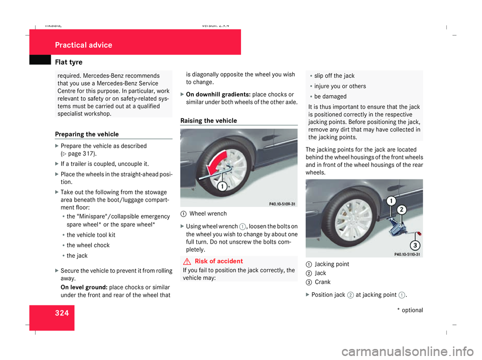
Raising the vehicle 1
Wheel wrench
X Using wheel wrench 1, loosen the bolts on
the wheel you wish to change by about one
full turn. Do not unscrew the bolts com-
pletely. G
Risk of accident
If you fail to position the jack correctly, the
vehicle may: R
slip off the jack
R injure you or others
R be damaged
It is thus important to ensure that the jack
is positioned correctly in the respective
jacking points. Before positioning the jack,
remove any dirt that may have collected in
the jacking points.
The jacking points for the jack are located
behind the wheel housings of the front wheels
and in front of the wheel housings of the rear
wheels. 1
Jacking point
2 Jack
3 Crank
X Position jack 2at jacking point 1. Practical advice
* optional
211_AKB; 2; 5, en-GB
mkalafa,
Version: 2.9.4 2008-02-29T16:57:07+01:00 - Seite 324Dateiname: 6515_3416_02_buchblock.pdf; preflight
Page 328 of 401
Flat tyre
325X
Make sure that the base of the jack is posi-
tioned directly under jacking point 1.
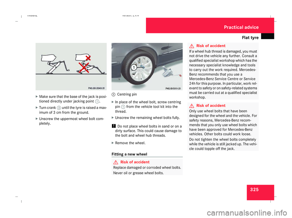
X Turn crank 3until the tyre is raised a max-
imum of 3 cm from the ground.
X Unscrew the uppermost wheel bolt com-
pletely. 1
Centring pin
X In place of the wheel bolt, screw centring
pin 1from the vehicle tool kit into the
thread.
X Unscrew the remaining wheel bolts fully.
! Do not place wheel bolts in sand or on a
dirty surface. This could cause damage to
the bolt and wheel hub threads.
X Remove the wheel.
Fitting a new wheel G
Risk of accident
Replace damaged or corroded wheel bolts.
Never oil or grease wheel bolts. G
Risk of accident
If a wheel hub thread is damaged, you must
not drive the vehicle any further. Consult a
qualified specialist workshop which has the
necessary specialist knowledge and tools
to carry out the work required. Mercedes-
Benz recommends that you use a
Mercedes-Benz Service Centre or Service
24h for this purpose. In particular, work rel-
evant to safety or on safety-related systems
must be carried out at a qualified specialist
workshop. G
Risk of accident
Only use wheel bolts that have been
designed for the wheel and the vehicle. For
safety reasons, Mercedes-Benz recom-
mends that you only use wheel bolts which
have been approved for Mercedes-Benz
vehicles. Other bolts could work loose.
Do not tighten the wheel bolts completely
while the vehicle is still jacked up. The vehi-
cle could topple off the jack. Practical advice
211_AKB; 2; 5, en-GB
mkalafa,
Version: 2.9.4 2008-02-29T16:57:07+01:00 - Seite 325 ZDateiname: 6515_3416_02_buchblock.pdf; preflight
Page 329 of 401
Flat tyre
3261
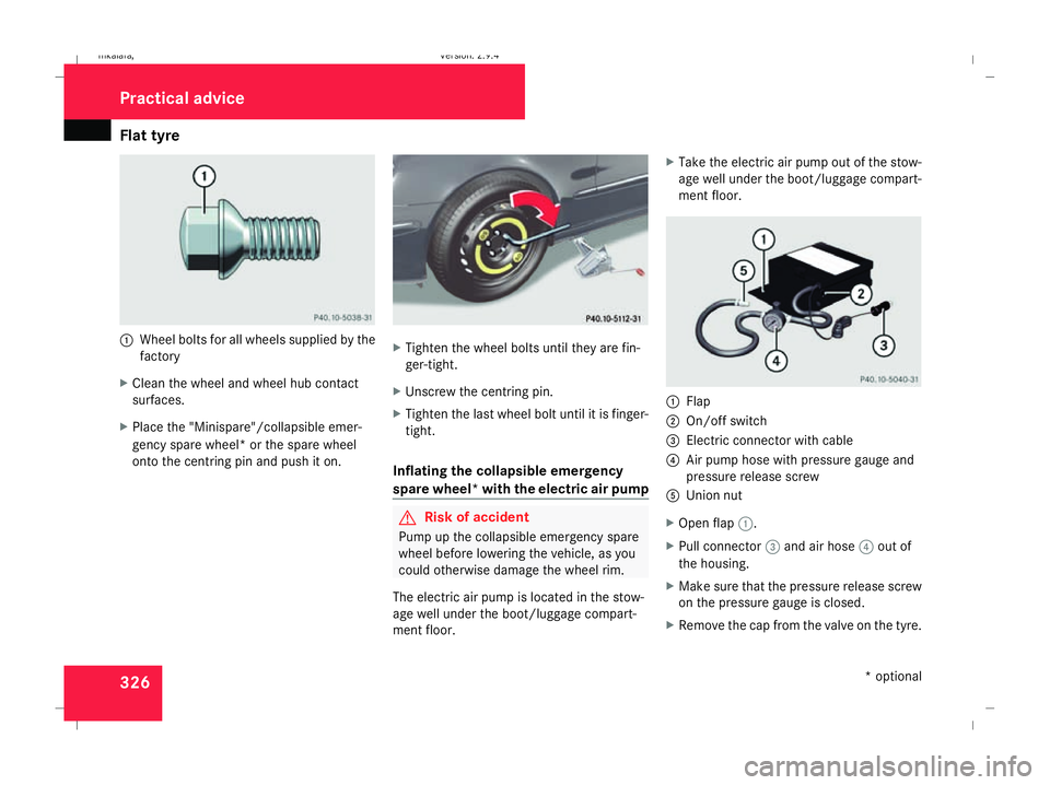
Wheel bolts for all wheels supplied by the
factory
X Clean the wheel and wheel hub contact
surfaces.
X Place the "Minispare"/collapsible emer-
gency spare wheel* or the spare wheel
onto the centring pin and push it on. X
Tighten the wheel bolts until they are fin-
ger-tight.
X Unscrew the centring pin.
X Tighten the last wheel bolt until it is finger-
tight.
Inflating the collapsible emergency
spare wheel* with the electric air pump G
Risk of accident
Pump up the collapsible emergency spare
wheel before lowering the vehicle, as you
could otherwise damage the wheel rim.
The electric air pump is located in the stow-
age well under the boot/luggage compart-
ment floor. X
Take the electric air pump out of the stow-
age well under the boot/luggage compart-
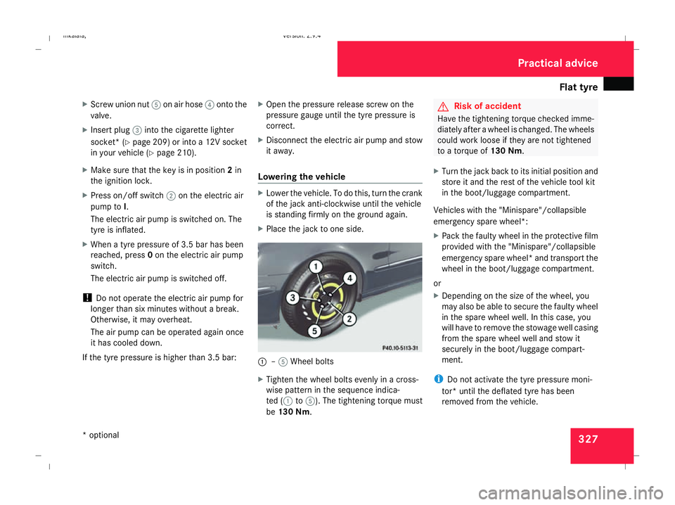
ment floor. 1
Flap
2 On/off switch
3 Electric connector with cable
4 Air pump hose with pressure gauge and
pressure release screw
5 Union nut
X Open flap 1.
X Pull connector 3and air hose 4out of
the housing.
X Make sure that the pressure release screw
on the pressure gauge is closed.
X Remove the cap from the valve on the tyre. Practical advice
* optional
211_AKB; 2; 5, en-GB
mkalafa,
Version: 2.9.4 2008-02-29T16:57:07+01:00 - Seite 326Dateiname: 6515_3416_02_buchblock.pdf; preflight
Page 330 of 401
Flat tyre
327
X
Screw union nut 5on air hose 4onto the
valve.
X Insert plug 3into the cigarette lighter
socket* ( Ypage 209) or into a 12V socket
in your vehicle (Y page 210).
X Make sure that the key is in position 2in
the ignition lock.
X Press on/off switch 2on the electric air
pump to I.
The electric air pump is switched on. The
tyre is inflated.
X When a tyre pressure of 3.5 bar has been
reached, press 0on the electric air pump
switch.
The electric air pump is switched off.
! Do not operate the electric air pump for
longer than six minutes without a break.
Otherwise, it may overheat.
The air pump can be operated again once
it has cooled down.
If the tyre pressure is higher than 3.5 bar: X
Open the pressure release screw on the
pressure gauge until the tyre pressure is
correct.
X Disconnect the electric air pump and stow
it away.
Lowering the vehicle X
Lower the vehicle. To do this, turn the crank
of the jack anti-clockwise until the vehicle
is standing firmly on the ground again.
X Place the jack to one side. 1
–5 Wheel bolts
X Tighten the wheel bolts evenly in a cross-
wise pattern in the sequence indica-
ted ( 1to5). The tightening torque must
be 130 Nm . G
Risk of accident
Have the tightening torque checked imme-
diately after a wheel is changed. The wheels
could work loose if they are not tightened
to a torque of 130 Nm.
X Turn the jack back to its initial position and
store it and the rest of the vehicle tool kit
in the boot/luggage compartment.
Vehicles with the "Minispare"/collapsible
emergency spare wheel*:
X Pack the faulty wheel in the protective film
provided with the "Minispare"/collapsible
emergency spare wheel* and transport the
wheel in the boot/luggage compartment.
or
X Depending on the size of the wheel, you
may also be able to secure the faulty wheel
in the spare wheel well. In this case, you
will have to remove the stowage well casing
from the spare wheel well and stow it
securely in the boot/luggage compart-
ment.
i Do not activate the tyre pressure moni-
tor* until the deflated tyre has been
removed from the vehicle. Practical advice
* optional
211_AKB; 2; 5, en-GB
mkalafa,
Version: 2.9.4 2008-02-29T16:57:07+01:00 - Seite 327 ZDateiname: 6515_3416_02_buchblock.pdf; preflight