MERCEDES-BENZ E-CLASS SALOON 2008 Owners Manual
Manufacturer: MERCEDES-BENZ, Model Year: 2008, Model line: E-CLASS SALOON, Model: MERCEDES-BENZ E-CLASS SALOON 2008Pages: 401, PDF Size: 6.89 MB
Page 341 of 401
Towing and tow-starting
338-
you cannot switch on the ignition
- you cannot move the selector lever
to N(on vehicles with automatic trans-
mission*)
- you have no support when braking
i Switch off the automatic locking feature
before the vehicle is towed (Y page 137).
You could otherwise be locked out when
pushing or towing the vehicle. Fitting the towing eye
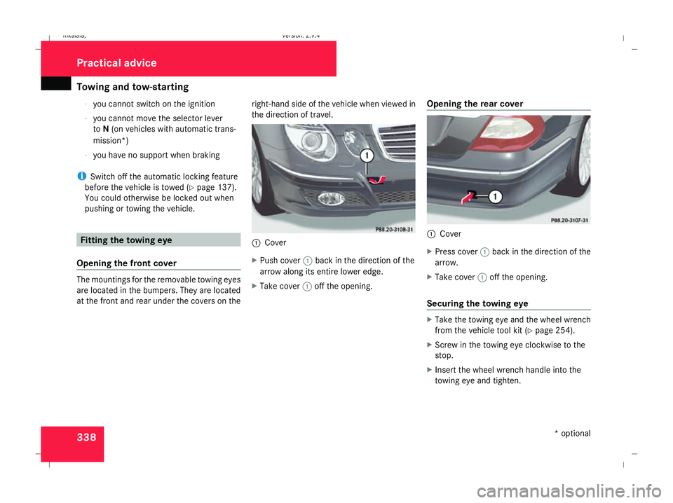
Opening the front cover The mountings for the removable towing eyes
are located in the bumpers. They are located
at the front and rear under the covers on the right-hand side of the vehicle when viewed in
the direction of travel. 1
Cover
X Push cover 1back in the direction of the
arrow along its entire lower edge.
X Take cover 1off the opening. Opening the rear cover 1
Cover
X Press cover 1back in the direction of the
arrow.
X Take cover 1off the opening.
Securing the towing eye X
Take the towing eye and the wheel wrench
from the vehicle tool kit ( Ypage 254).
X Screw in the towing eye clockwise to the
stop.
X Insert the wheel wrench handle into the
towing eye and tighten. Practical advice
* optional
211_AKB; 2; 5, en-GB
mkalafa
,V ersion: 2.9.4
2008-02-29T16:57:07+01:00 - Seite 338 Dateiname: 6515_3416_02_buchblock.pdf; preflight
Page 342 of 401
Towing and tow-starting
339Towing the vehicle
! You may tow the vehicle for a maximum
of 50 km. A towing speed of 50 km/h must
not be exceeded.
With towing distances over 50 km, the
entire vehicle needs to be lifted up and
transported.
! Vehicles with 4MATIC* may not be towed
with the front or rear axle raised.
! The engine must be switched off (key in
ignition lock in position 0or position 1) if
the vehicle is being towed with the rear axle
raised or if the parking brake is being tested
on a dynamometer. Intervention by ESP ®
could otherwise damage the brake system.
Vehicles with manual transmission X
Turn the key to position 2in the ignition
lock.
X Shift to neutral. Vehicles with automatic transmission* X
Turn the key to position 2in the ignition
lock.
X Move the selector lever to N. Tow-starting (emergency engine
starting)
Please note:
R Vehicles with an automatic transmission*
must not be tow-started.
R The battery must be connected.
R The engine and catalytic converter must be
cold.
R Avoid repeated and lengthy starting
attempts.
Vehicles with manual transmission X
Turn the key to position 2in the ignition
lock.
X Fully depress the clutch pedal.
X Shift to neutral. X
Tow the vehicle or let it roll.
X Shift to a suitable gear and bring the clutch
pedal up slowly. Do not depress the accel-
erator pedal.
The engine is started. Removing the towing eye
X Take the wheel wrench from the vehicle
tool kit ( Ypage 254).
X Insert the wheel wrench handle into the
towing eye and turn it anti-clockwise.
X Unscrew the towing eye.
X Replace the cover and press it until it
engages.
X Return the towing eye and the wheel
wrench to the vehicle tool kit. Practical advice
* optional
211_AKB; 2; 5, en-GB
mkalafa
,V ersion: 2.9.4
2008-02-29T16:57:07+01:00 - Seite 339 ZDateiname: 6515_3416_02_buchblock.pdf; preflight
Page 343 of 401
Fuses
340 Transporting the vehicle
The towing eyes can be used to pull the vehi-
cle onto a trailer or transporter for transport-
ing purposes.
! Only lash the vehicle down by the wheels
or wheel rims, not by parts of the vehicle
such as axle or steering components. The
vehicle could otherwise be damaged.
Vehicles with manual transmission X
Shift to neutral.
Vehicles with automatic transmission* X
Turn the key to position 2in the ignition
lock.
X Move the selector lever to N. Fuses
Notes on changing fuses
The fuses in your vehicle serve to close down
faulty circuits. If a fuse blows, all the compo-
nents on the circuit and their functions will
fail.
Blown fuses must be replaced with fuses of
the same rating, which you can recognise by
the colour and value. The fuse ratings are lis-
ted in the fuse allocation chart. A Mercedes-
Benz Service Centre will be happy to advise
you. G
Risk of fire
Only use fuses that have been approved for
Mercedes-Benz vehicles and which have
the correct fuse rating for the systems con-
cerned. Do not attempt to repair or bridge
faulty fuses. Otherwise, a circuit overload
could cause a fire. Have the cause traced
and rectified at a qualified specialist work-
shop, e.g. a Mercedes-Benz Service Centre.
If the newly inserted fuse also blows, have the
cause traced and rectified at a qualified spe-
cialist workshop, e.g. a Mercedes-Benz
Service Centre. !
Only use fuses that have been approved
for Mercedes-Benz vehicles and which
have the correct fuse rating for the system
concerned. Otherwise, components or sys-
tems could be damaged.
The fuses are located in various fuse boxes:
R Main fuse box on the driver's side of the
dashboard
R Fuse box in the boot/luggage compart-
ment on the left-hand side of the vehicle
Fuse allocation chart The fuse allocation chart is in the main fuse
box in the dashboard.
Before changing a fuse
X Park the vehicle.
X Switch off all electrical consumers.
X Remove the key from the ignition lock. Practical advice
* optional
211_AKB; 2; 5, en-GB
mkalafa,
Version: 2.9.4 2008-02-29T16:57:07+01:00 - Seite 340Dateiname: 6515_3416_02_buchblock.pdf; preflight
Page 344 of 401
Fuses
341Main fuse box
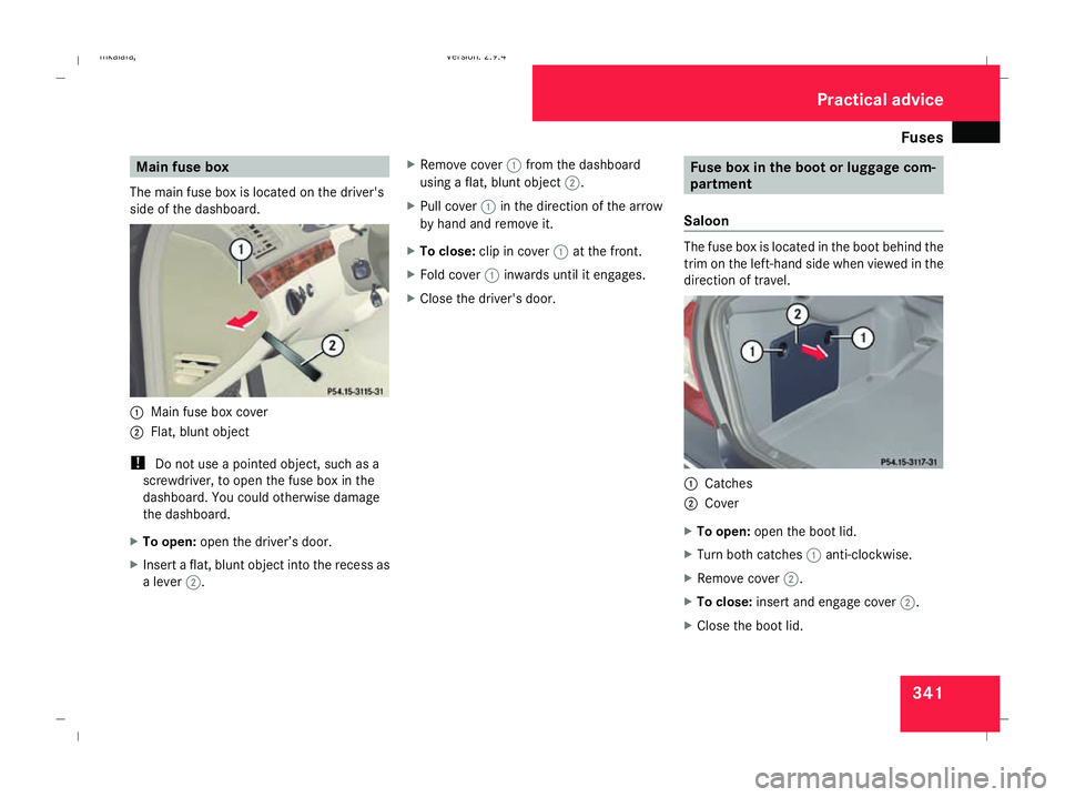
The main fuse box is located on the driver's
side of the dashboard. 1
Main fuse box cover
2 Flat, blunt object
! Do not use a pointed object, such as a
screwdriver, to open the fuse box in the
dashboard. You could otherwise damage
the dashboard.
X To open: open the driver’s door.
X Insert a flat, blunt object into the recess as
a lever 2. X
Remove cover 1from the dashboard
using a flat, blunt object 2.
X Pull cover 1in the direction of the arrow
by hand and remove it.
X To close: clip in cover 1at the front.
X Fold cover 1inwards until it engages.
X Close the driver's door. Fuse box in the boot or luggage com-
partment
Saloon The fuse box is located in the boot behind the
trim on the left-hand side when viewed in the
direction of travel.
1
Catches
2 Cover
X To open: open the boot lid.
X Turn both catches 1anti-clockwise.
X Remove cover 2.
X To close: insert and engage cover 2.
X Close the boot lid. Practical advice
211_AKB; 2; 5, en-GB
mkalafa,
Version: 2.9.4 2008-02-29T16:57:07+01:00 - Seite 341 ZDateiname: 6515_3416_02_buchblock.pdf; preflight
Page 345 of 401
Fuses
342
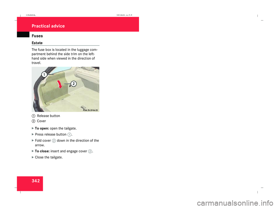
Estate The fuse box is located in the luggage com-
partment behind the side trim on the left-
hand side when viewed in the direction of
travel. 1
Release button
2 Cover
X To open: open the tailgate.
X Press release button 1.
X Fold cover 2down in the direction of the
arrow.
X To close: insert and engage cover 2.
X Close the tailgate. Practical advice
211_AKB; 2; 5, en-GB
mkalafa,
Version: 2.9.4 2008-02-29T16:57:07+01:00 - Seite 342Dateiname: 6515_3416_02_buchblock.pdf; preflight
Page 346 of 401
343
Introduction to technical data
.........344
Genuine Mercedes-Benz parts .........344
Vehicle electronics ...........................345
Vehicle identification plates ............346
Engine ................................................ 348
Performance ...................................... 352
Tyres and wheels .............................. 356
Vehicle dimensions ..........................366
Vehicle weights ................................. 369
Trailer coupling* ............................... 375
Service products and capacities .....377
Frequencies for garage door open-
ers* .................................................... 391 Technical data
211_AKB; 2; 5, en-GB
mkalafa,
Version: 2.9.4 2008-02-29T16:57:07+01:00 - Seite 343Dateiname: 6515_3416_02_buchblock.pdf; preflight
Page 347 of 401
Genuine Mercedes-Benz parts
344 Introduction to technical data
i The technical data was determined in
accordance with EU directives. All data
applies to the vehicle's standard equip-
ment. The data may therefore differ for
vehicles with optional equipment. You can
obtain further information from a
Mercedes-Benz Service Centre. Genuine Mercedes-Benz parts
Mercedes-Benz tests genuine parts and con-
version parts and accessories which have
been specifically approved for your vehicle for
their reliability, safety and suitability. Despite
ongoing market research, Mercedes-Benz is
unable to evaluate other parts. Mercedes-
Benz therefore accepts no responsibility for
the use of such parts in Mercedes-Benz vehi-
cles, even if they have been independently or
officially approved.
In Germany and some other countries, certain
parts are only officially approved for installa-
tion or modification if they comply with legal
requirements. All genuine Mercedes-Benz
parts meet this requirement. The use of non-
approved parts may invalidate the vehicle's
general operating permit. This is the case if:
R they cause a change of the vehicle type
from that for which the vehicle's general
operating permit was granted
R other road users could be endangered
R the emission or noise levels are adversely
affected
The use of non-approved parts could affect
your vehicle's operating safety. Mercedes-
Benz therefore recommends genuine Mercedes-Benz parts and conversion parts
and accessories that have been approved for
your vehicle. H
Environmental note
Daimler also supplies reconditioned
assemblies and parts which are of the same
quality as new parts and to which the same
warranty applies.
Genuine Mercedes-Benz parts and approved
conversion parts and accessories are availa-
ble from Mercedes-Benz Service Centres.
There, you can also receive advice about tech-
nical modifications and have the parts pro-
fessionally fitted.
Always quote the vehicle identification num-
ber and the engine number when ordering
genuine parts. You will find these numbers on
the vehicle data card in the Service Booklet
or on your vehicle's identification plates
(Y page 346). Technical data
211_AKB; 2; 5, en-GB
mkalafa,
Version: 2.9.4 2008-02-29T16:57:07+01:00 - Seite 344Dateiname: 6515_3416_02_buchblock.pdf; preflight
Page 348 of 401
Vehicle electronics
345Vehicle electronics
Tampering with the engine electron-
ics
G
Risk of accident
Only have work on the engine electronics
and related components carried out at a
qualified specialist workshop which has the
necessary specialist knowledge and tools
to carry out the work required. Mercedes-
Benz recommends that you use a
Mercedes-Benz Service Centre for this pur-
pose. In particular, work relevant to safety
or on safety-related systems must be car-
ried out at a qualified specialist workshop.
The vehicle's roadworthiness could other-
wise be affected.
! Only have work done on the engine elec-
tronics and its associated parts, such as
control units, sensors and connector leads,
carried out at a qualified specialist work-
shop, e.g. a Mercedes-Benz Service
Centre. Otherwise, vehicle components
may wear more quickly and your vehicle's
warranty and operating permit may be inva-
lidated. Retrofitting electrical and electronic
equipment
Electrical and electronic equipment can jeop-
ardise the operating safety of your vehicle. If
equipment of this kind is retrofitted, it must
be type-approved and bear the emark. The
e mark may be obtained from the equipment
manufacturer or an authorised testing centre.
! Damage or consequential damage arising
from fitting equipment not approved
by Mercedes-Benz is not covered by the
Mercedes-Benz warranty.
If you wish to install two-way radios in the
vehicle, you must obtain formal approval.
Mercedes-Benz approves the installation of
two-way radios if such equipment is installed
professionally and a low-reflection exterior
aerial is used.
The transmission output of the two-way radio
must not exceed the maximum transmission
outputs listed. G
Risk of accident
Two-way radios may interfere with the vehi-
cle electronics and thereby jeopardise the
operational safety of the vehicle and your
own safety if: R
they do not have an exterior aerial
R the exterior aerial is not a low-reflection
aerial
R the exterior aerial has been fitted incor-
rectly G
Risk of injury
Excessive electromagnetic radiation may
also cause damage to your health and the
health of others. Using an exterior aerial
takes into account current scientific dis-
cussions relating to the possible health haz-
ards that may result from electromagnetic
fields.
For this reason, only have the exterior aerial
fitted at a qualified specialist workshop
which has the necessary specialist knowl-
edge and tools to carry out the work
required. Mercedes-Benz recommends
that you use a Mercedes-Benz Service
Centre for this purpose. In particular, work
relevant to safety or on safety-related sys-
tems must be carried out at a qualified
specialist workshop.
i Mercedes-Benz recommends the use of
an approved exterior aerial. This ensures
optimal reception quality for mobile tele- Technical data
211_AKB; 2; 5, en-GB
mkalafa,
Version: 2.9.4
2008-02-29T16:57:07+01:00 - Seite 345 ZDateiname: 6515_3416_02_buchblock.pdf; preflight
Page 349 of 401
Vehicle identification plates
346phones/wireless devices in the vehicle.
This also ensures that interference
between these devices and the vehicle's
electronics is kept to a minimum. If instal-
led, the exterior aerial conducts the elec-
tromagnetic fields transmitted by a mobile
phone to the exterior of the vehicle. Frequency range Maximum trans-
mission output
(watts)
Short wave
(< 50 MHz) 100
4 m waveband 20
2 m waveband 50
70 cm waveband 35
25 cm waveband 10
!
If electrical or electronic equipment
which does not comply with the above
installation conditions is operated inside
the vehicle, the vehicle's operating permit
may be invalidated (EU Directive
95/54/EC) - Automotive EMC directive) Vehicle identification plates
Vehicle identification plate with vehi-
cle identification number (VIN) and
paint code number
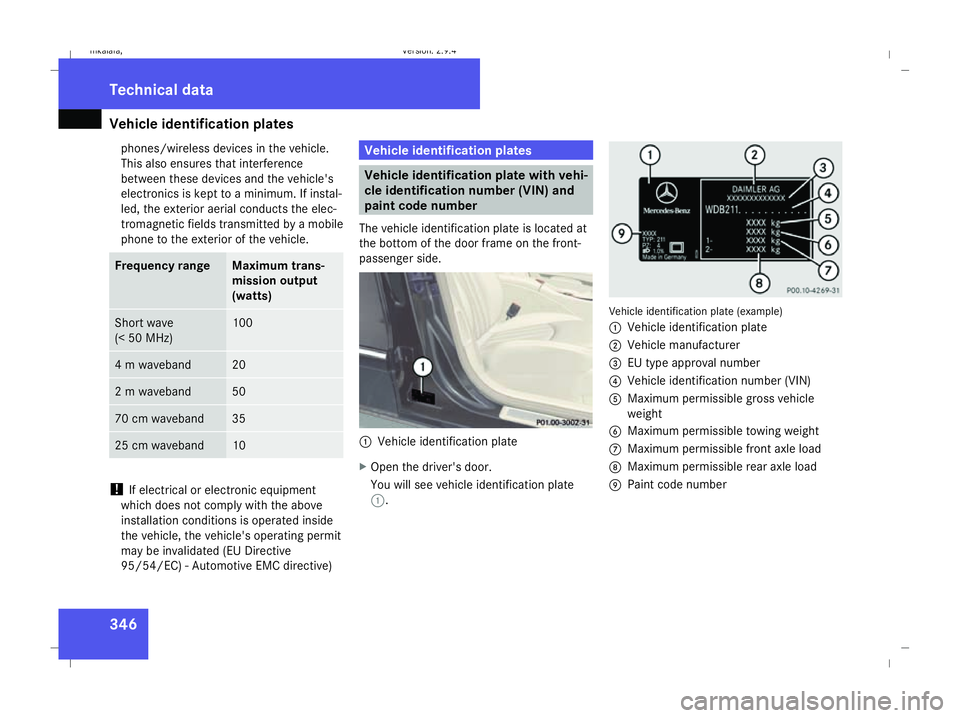
The vehicle identification plate is located at
the bottom of the door frame on the front-
passenger side. 1
Vehicle identification plate
X Open the driver's door.
You will see vehicle identification plate
1. Vehicle identification plate (example)
1
Vehicle identification plate
2 Vehicle manufacturer
3 EU type approval number
4 Vehicle identification number (VIN)
5 Maximum permissible gross vehicle
weight
6 Maximum permissible towing weight
7 Maximum permissible front axle load
8 Maximum permissible rear axle load
9 Paint code number Technical data
211_AKB; 2; 5, en-GB
mkalafa,
Version: 2.9.4
2008-02-29T16:57:07+01:00 - Seite 346 Dateiname: 6515_3416_02_buchblock.pdf; preflight
Page 350 of 401
Vehicle identification plates
347Vehicle identification number (VIN)
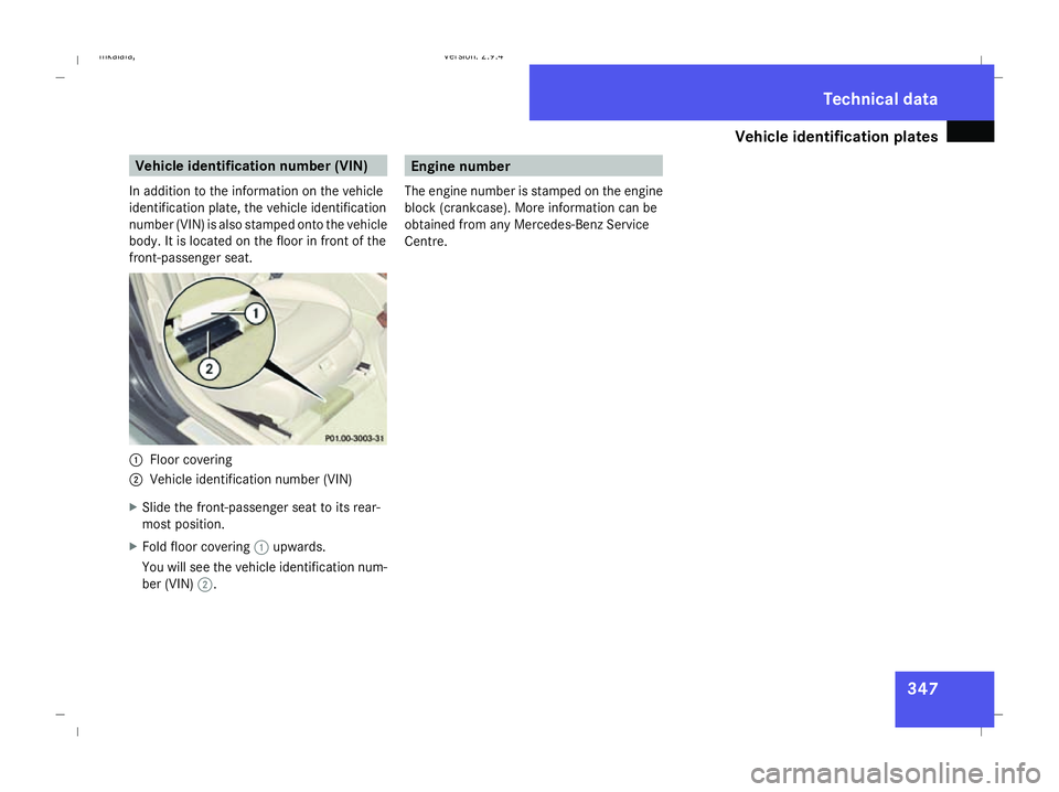
In addition to the information on the vehicle
identification plate, the vehicle identification
number (VIN) is also stamped onto the vehicle
body. It is located on the floor in front of the
front-passenger seat. 1
Floor covering
2 Vehicle identification number (VIN)
X Slide the front-passenger seat to its rear-
most position.
X Fold floor covering 1upwards.
You will see the vehicle identification num-
ber (VIN) 2. Engine number
The engine number is stamped on the engine
block (crankcase). More information can be
obtained from any Mercedes-Benz Service
Centre. Technical data
211_AKB; 2; 5, en-GB
mkalafa
, Version: 2.9.4 2008-02-29T16:57:07+01:00 - Seite 347 ZDateiname: 6515_3416_02_buchblock.pdf; preflight