MERCEDES-BENZ E-CLASS SALOON 2015 Owners Manual
Manufacturer: MERCEDES-BENZ, Model Year: 2015, Model line: E-CLASS SALOON, Model: MERCEDES-BENZ E-CLASS SALOON 2015Pages: 497, PDF Size: 16.23 MB
Page 271 of 497
The maximum permissible speed for vehicle/
trailer combinations depends on the type of
trailer. Before beginnin gthe journey, check
the trailer's document stosee what the max-
imum permitted speed is. Observe the legally
prescribed maximum speed in the relevant
country.
For certain Mercedes-Benz vehicles, the max-
imum permissible rear axle load is increased
when towing atrailer. See the "Technical
data" section to find out whether this applies to your vehicle (Y page 484). If you utilise any
of the added maximum rear axle load when
towing atrailer, the vehicle/trailer combina-
tion may not exceed amaximum speed of
100 km/hf or reasons concerning the oper-
ating permit. This also applie sincountrie sin
which the permissible maximu mspee dfor
vehicle/trailer combinations is above
100 km/h.
When towing atrailer, you rvehicle's handling
characteristics wil lbedifferent in comparison
to whe ndriving without atrailer and it will
consume more fuel.
Change into alower gea ringood time on long
and steep downhill gradients.
i This also applie
sifyou have activated
cruis econtrol, SPEEDTRONIC or
DISTRONIC PLUS.
This wil luse the braking effect of the engine,
so less braking wil lberequired to maintain
vehicle speed. This relieves the loa donthe
brake system and prevents the brake sfrom
overheating and wearing too quickly. If you
need additiona lbraking, depress the brake
pedal repeatedl yrather than continuously.
Driving tips If the trailer swings from side to side:
X Do not accelerate.
X Do not countersteer.
X Brake if necessary. R
Maintain agreater distance to the vehicle in
front than whe ndriving without atrailer.
R Avoid braking abruptly .Ifpossible ,brake
gently at first to allow the trailer to run on.
Then, increase the braking force rapidly.
R The values give nfor gradient-climbing
capabilities from astandstil lrefer to sea
level. When driving in mountainous areas,
note that the power outpu tofthe engine,
and consequently the vehicle's gradient-
climbing capability, decrease with increas-
ing altitude. Foldin
gout the ball coupling G
WARNING
If the bal lcoupling is not correctly engaged,
the trailer can detach .There is arisk of an
accident.
Always engag ethe bal lcoupling as described. G
WARNING
If you release the bal lcoupling or it does not
engag ecorrectly whe nfolding in, it wil lswing
out. Withi npivoting range of the bal lcoupling,
there is an increased risk of an accident and
injury.
Only release the bal lcoupling if the pivoting
range is unobstructed. Always make sure that the bal lcoupling engages whe nfolding in. Saloon
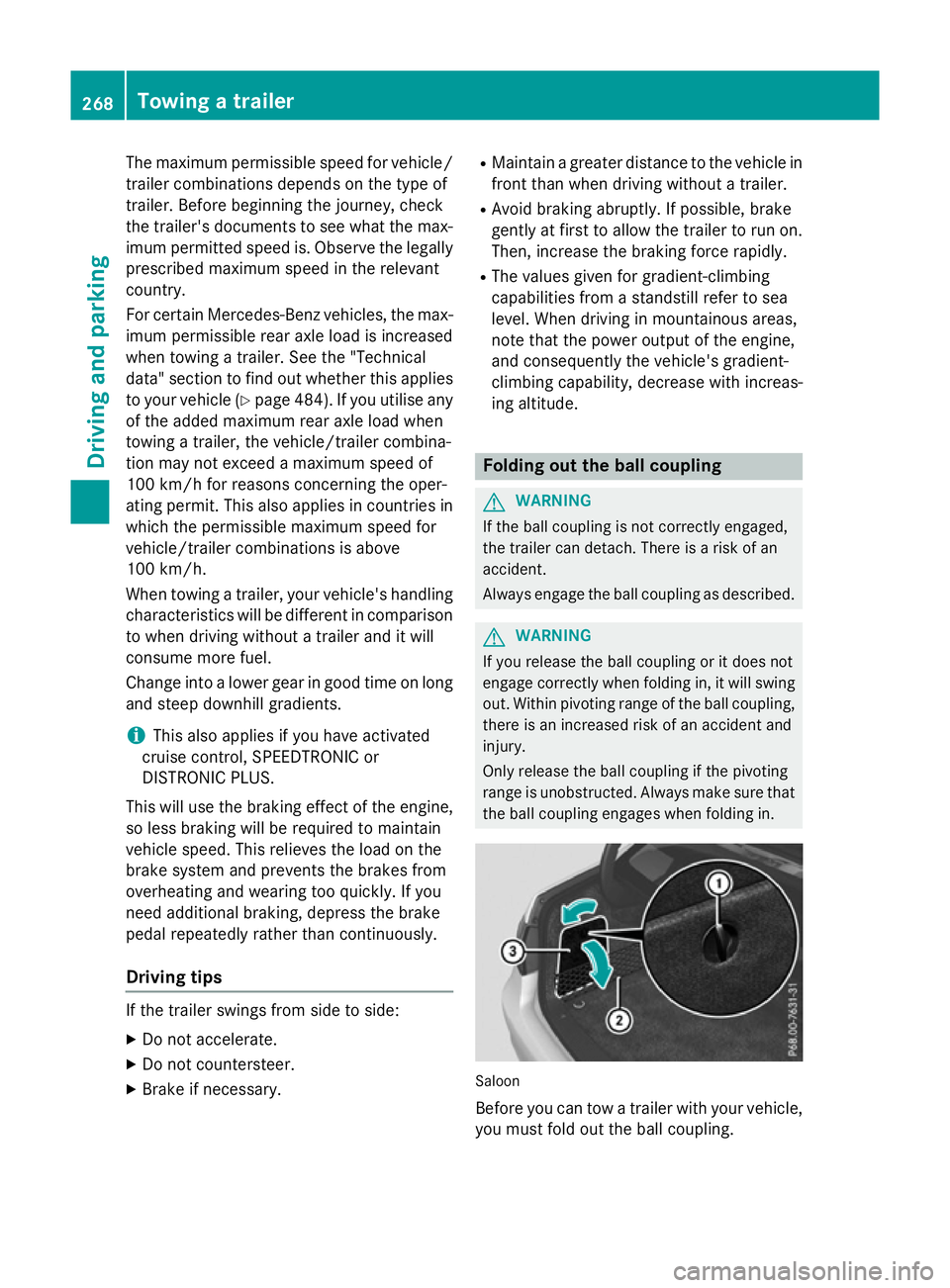
Before you can tow
atrailer with you rvehicle,
you must fold out the bal lcoupling. 268
Towing
atrailerDriving and parking
Page 272 of 497
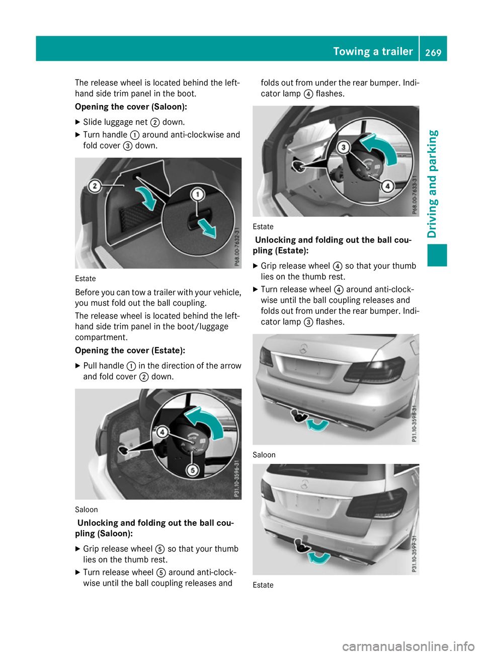
The release wheel is located behind the left-
hand side trim panel in the boot.
Opening the cover (Saloon):
X Slide luggage net ;down.
X Turn handle :around anti-clockwise and
fold cover =down. Estate
Before you can tow
atrailer with your vehicle,
you must fold out the ball coupling.
The release wheel is located behind the left-
hand side trim panel in the boot/luggage
compartment.
Opening the cover (Estate):
X Pull handle :in the direction of the arrow
and fold cover ;down. Saloon
Unlocking and folding out the ball cou-
pling (Saloon):
X Grip release wheel Aso that your thumb
lies on the thumb rest.
X Turn release wheel Aaround anti-clock-
wise until the ball coupling releases and folds out from under the rear bumper. Indi-
cator lamp ?flashes. Estate
Unlocking and folding out the ball cou-
pling (Estate):
X Grip release wheel ?so that your thumb
lies on the thumb rest.
X Turn release wheel ?around anti-clock-
wise until the ball coupling releases and
folds out from under the rear bumper. Indi- cator lamp =flashes. Saloon
Estate Towing
atrailer
269Driving and parking Z
Page 273 of 497
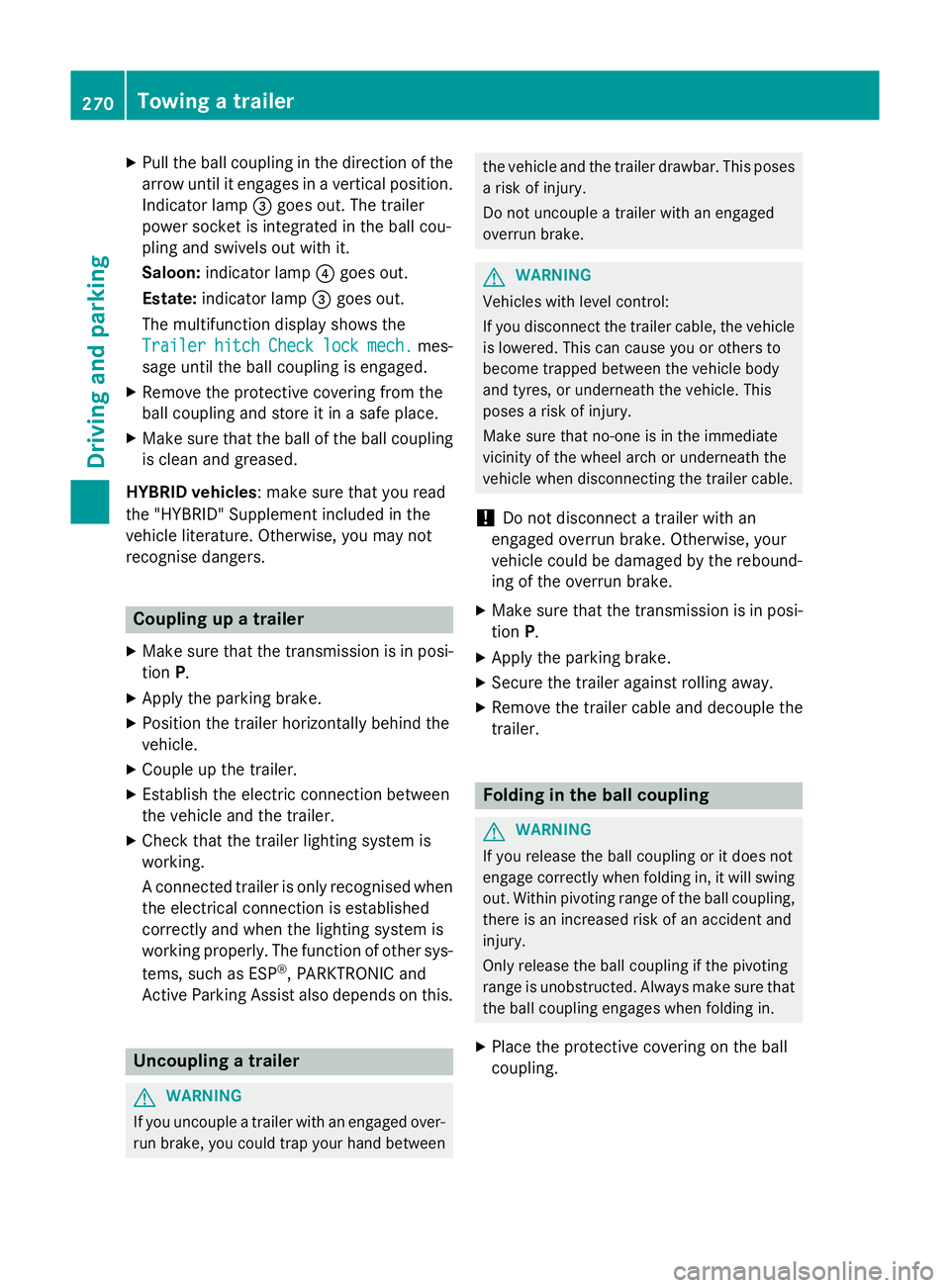
X
Pull the ball coupling in the direction of the
arrow until it engages in avertical position.
Indicator lamp =goes out. The trailer
power socket is integrated in the ball cou-
pling and swivels out with it.
Saloon: indicator lamp ?goes out.
Estate: indicator lamp =goes out.
The multifunction display shows the
Trailer Trailer hitch
hitch Check
Checklock
lockmech.
mech. mes-
sage until the ball coupling is engaged.
X Remove the protective coverin gfrom the
ball coupling and store it in asafe place.
X Make sure that the ball of the ball coupling
is clean and greased.
HYBRID vehicles :make sure that you read
the "HYBRID" Supplement included in the
vehicle literature. Otherwise, you may not
recognise dangers. Coupling up
atrailer
X Make sure that the transmission is in posi-
tion P.
X Apply the parking brake.
X Position the trailer horizontally behind the
vehicle.
X Couple up the trailer.
X Establish the electric connection between
the vehicle and the trailer.
X Check that the trailer lighting system is
working.
Ac onnected trailer is only recognised when
the electrical connection is established
correctly and when the lighting system is
working properly. The function of other sys-
tems, such as ESP ®
,P ARKTRONIC and
Active Parking Assist also depends on this. Uncoupling
atrailer G
WARNING
If you uncouple atrailer with an engaged over-
run brake, you could trap your hand between the vehicle and the trailer drawbar. This poses
ar isk of injury.
Do not uncouple atrailer with an engaged
overrun brake. G
WARNING
Vehicles with level control:
If you disconnect the trailer cable, the vehicle is lowered. This can cause you or others to
become trapped between the vehicle body
and tyres, or underneat hthe vehicle. This
poses arisk of injury.
Make sure that no-one is in the immediate
vicinit yofthe wheel arch or underneat hthe
vehicle when disconnectin gthe trailer cable.
! Do not disconnect
atrailer with an
engaged overrun brake. Otherwise, your
vehicle could be damaged by the rebound- ing of the overrun brake.
X Make sure that the transmission is in posi-
tion P.
X Apply the parking brake.
X Secure the trailer against rolling away.
X Remove the trailer cable and decouple the
trailer. Folding in the ball coupling
G
WARNING
If you release the ball coupling or it does not
engage correctly when folding in, it will swing out. Within pivoting range of the ball coupling,
there is an increased risk of an accident and
injury.
Only release the ball coupling if the pivoting
range is unobstructed. Always make sure that the ball coupling engages when folding in.
X Place the protective coverin gonthe ball
coupling. 270
Towing
atrailerDriving and parking
Page 274 of 497
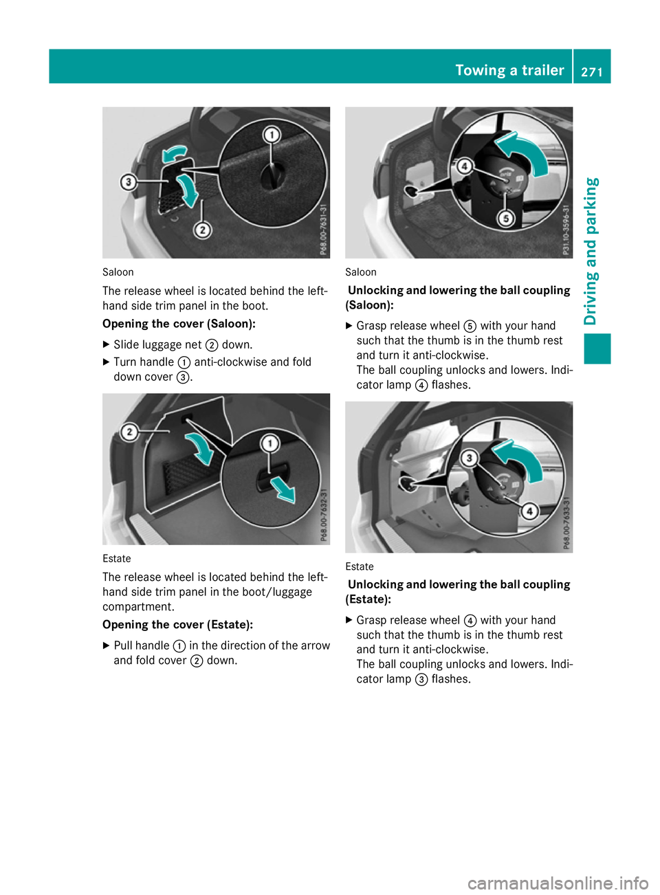
Saloon
The release wheel is located behind the left-
hand sid etrim panel in the boot.
Opening the cover (Saloon):
X Slide luggage net ;down.
X Turn handle :anti-clockwise and fold
dow ncover =. Estate
The release wheel is located behind the left-
hand sid etrim panel in the boot/luggage
compartment.
Opening the cover (Estate):
X Pull handle :in the direction of the arrow
and fol dcover ;down. Saloon
Unlockin gand lowering the bal lcou pling
(Saloon):
X Grasp release wheel Awith your hand
such that the thum bisinthe thum brest
and turn it anti-clockwise.
The ball coupling unlocks and lowers. Indi-
cator lamp ?flashes. Estate
Unlockin gand lowering the bal lcou pling
(Estate):
X Grasp release wheel ?with your hand
such that the thum bisinthe thum brest
and turn it anti-clockwise.
The ball coupling unlocks and lowers. Indi-
cator lamp =flashes. Towin
gatrailer
271Drivingand parking Z
Page 275 of 497
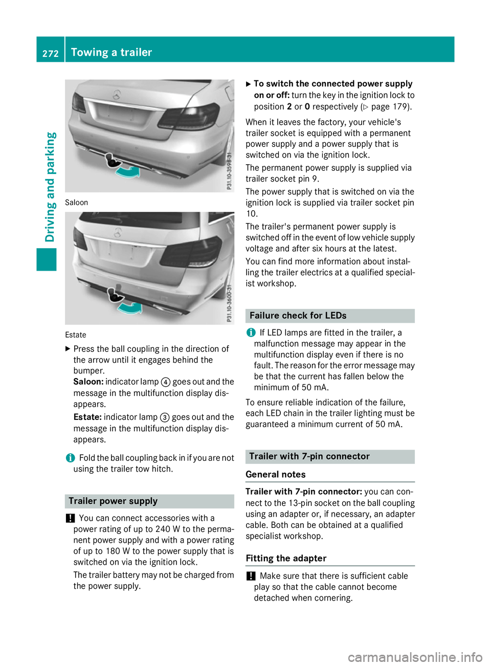
Saloon
Estate
X Press the ball coupling in the direction of
the arrow unti litengages behind the
bumper.
Saloon: indicator lamp ?goe soutand the
messag einthe multifunction display dis-
appears.
Estate: indicator lamp =goe soutand the
messag einthe multifunction display dis-
appears.
i Fol
dthe ball coupling back in if yo uare not
using the traile rtow hitch. Traile
rpower supply
! You can connect accessorie
switha
power rating of up to 240 Wtothe perma-
nent power suppl yand with apower rating
of up to 180 Wtothe power suppl ythat is
switched on via the ignition lock.
The traile rbattery may not be charge dfrom
the power supply. X
To switc hthe connecte dpower supply
on or off: turn the key in the ignition lock to
position 2or 0respectivel y(Ypage 179).
Whe nitleavest he factory, your vehicle's
traile rsocke tise quipped with apermanent
power suppl yand apower suppl ythat is
switched on via the ignition lock.
The permanent power suppl yissupplie dvia
traile rsocke tpin9.
The power suppl ythat is switched on via the
ignition lock is supplie dvia traile rsocke tpin
10.
The trailer's permanent power suppl yis
switched off in the event of low vehicle supply
voltage and afte rsix hours at the latest.
You can find more information abou tinstal-
ling the traile relectrics at aquali fied special-
ist workshop. Failure check for LEDs
i If LED lamps are fitted in the trailer, a
malfunction messag emay appea rinthe
multifunction display eve nifthere is no
fault. The reason for the erro rmessag emay
be that the current ha sfalle nbelow the
minimum of 50 mA.
To ensure reliabl eindication of the failure,
each LED chain in the traile rlighting mus tbe
guaranteed aminimum current of 50 mA. Traile
rwith7 -pinc onnector
General notes Traile
rwith7 -pinc onnector: youc an con-
nect to the 13-pi nsocke tont he ball coupling
using an adapter or, if necessary, an adapter
cable .Both can be obtained at aquali fied
specialist workshop.
Fitting the adapter !
Make sure that there is sufficient cable
play so that the cable cannot become
detached when cornering. 272
Towin
gatrailerDrivin gand parking
Page 276 of 497
X
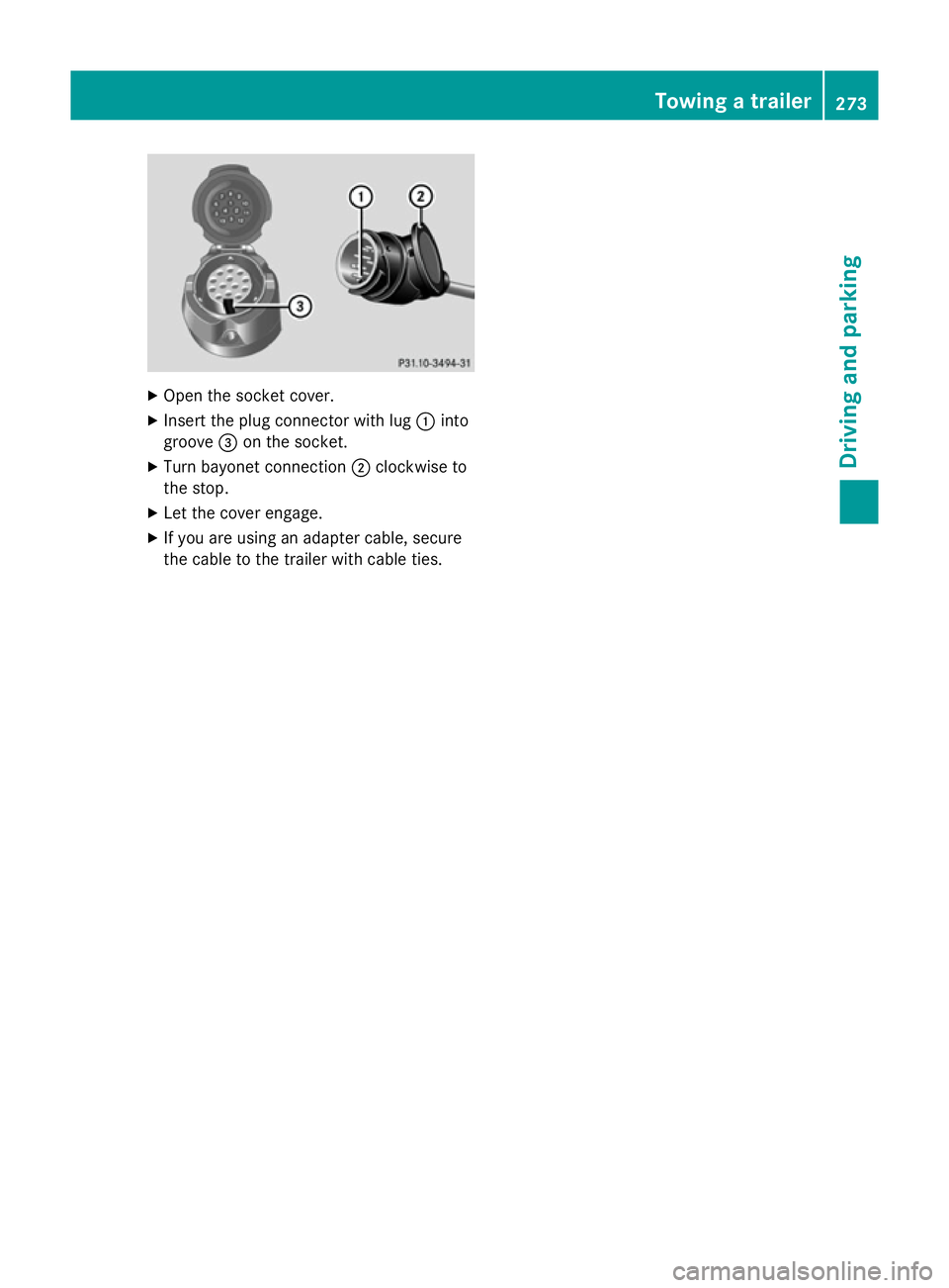
Open the socket cover.
X Insert the plug connector with lug :into
groove =on the socket.
X Turn bayonet connection ;clockwise to
the stop.
X Let the cover engage.
X If you are using an adapter cable, secure
the cable to the trailer with cable ties. Towing
atrailer
273Driving and parking Z
Page 277 of 497

274
Page 278 of 497
Useful information
............................276
Importan tsafet ynotes ..................... 276
Displays and operation ....................276
Menus and submenus ......................279
Display messages ............................. 299
Warning and indicator lamp sinthe
instrument cluster ............................329 275On-boar
dcomputer and displays
Page 279 of 497
Useful information
i This Owner's Manual describes all mod-
els, series and optional equipment for your
vehicle that were available at the time of
going to press. National variation sare pos-
sible. Not ethat your vehicle may not be
equipped with all of the function sdescri-
bed. This is also the case for system sand
function srelevan ttosafety.
i Read the information on qualified special-
ist workshops: (Y page 27). Important safet
ynotes G
WARNING
Operating the integrated information systems and communications equipment in the vehicle
while drivin gwill distract you from traffic con-
ditions. You could then lose contro lofthe
vehicle. There is arisk of an accident.
Only operate thes edevices if road traffic con-
dition spermit .Ifyou are unsure about the
surrounding conditions, pull over to asafe
locatio nand make entries only while the vehi-
cle is stationary.
You must observ ethe legal requirements for
the country in which you are currently driving when operatin gthe on-board computer. G
WARNING
If the instrumen tcluster has failed or mal-
functioned, you may not recognise function
restrictions relevan ttosafety. The operating
safet yofy our vehicle may be impaired. There
is ar isk of an accident.
Driv eonc arefully. Have the vehicle checked
at aq ualified specialist workshop immedi-
ately.
The on-board computer only shows messages
or warnings from certain system sinthe mul-
tifunction display. You should therefore make
sure your vehicle is operatin gsafely at all
times. If the operatin
gsafet yofy our vehicle is
impaired, park the vehicle safely as soon as
possible. Contact aqualified specialist work-
shop.
HYBRID vehicles :make sure that you read the
"HYBRID "Supplement. You could otherwise
fail to recognise dangers ,e.g. due to high
voltage.
For an overview; see the instrumen tcluster
illustration (Y page 34). Displays and operation
Coolant temperatureg
auge G
WARNING
If you open the bonnet while the engin eis
overheating or while ther eisafire in the
engin ecompartment, you could come into
contact with hot gases or other leaking ser-
vice products. There is adanger of injury.
Allow an overheating engin etocool down
before openin gthe bonnet. If ther eisafire in
the engin ecompartment, leave the bonnet
closed and notify the fire brigade.
The coolan ttemperature gauge is in the
instrumen tcluster on the left-hand side
(Y page 34).
Under normal operatin gcondition sand with
the specified coolan tlevel, the coolan ttem-
perature may rise to 120 †.
At high outside temperature sand when driv-
ing uphill, the coolan ttemperature may rise
to the end of the scale. Rev counter
! Do not drive in the overrevvin
grange.
Doin gsow ill damage the engine.
The red band in the rev counter indicates the
engine's overrevvin grange.
The fuel supply is interrupted to protect the
engin ewhen the red band is reached. 276
Displays and operationOn-boar
dcomputer and displays
Page 280 of 497
Outsid
etemperature display
You should pay special attention to road con-
ditions when temperatures are around the
freezing point.
Bear in mind that the outside temperature
display indicates the temperature measured
and does not recor dthe road temperature.
The outside temperature display is in the mul- tifunction display (Y page 279).
Changes in the outside temperature are dis-
played after ashort delay. Speedometer with segments
The segments in the speedometer indicate
which speed range is available.
R Cruise control activated (Y page 212):
The segments light up from the stored
speed to the maximum speed.
R Variable SPEEDTRONIC activated
(Y page 215):
The segments light up from the start of the
scale to the selected limit speed.
R DISTRONIC PLUS activated (Y page 217):
One or two segments in the set speed
range light up.
R DISTRONIC PLUS detects avehicle in front:
The segments between the speed of the
vehicle in fron tand the stored speed light
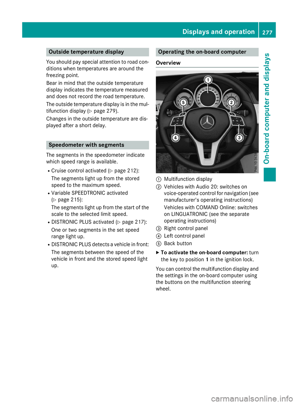
up. Operating the on-board computer
Overview :
Multifunction display
; Vehicles with Audio 20: switches on
voice-operated control for navigation (see
manufacturer's operatin ginstructions)
Vehicles with COMAND Online: switches
on LINGUATRONIC (see the separate
operatin ginstructions)
= Right control panel
? Left control panel
A Back button
X To activate the on-board computer: turn
the key to position 1in the ignition lock.
You can control the multifunction display and
the settings in the on-board computer using
the button sonthe multifunction steering
wheel. Displays and operation
277On-boardcomputer and displays Z